SECTION 2: INSTALLATION at 800 milliamperes when connected in series, but with
100volts at the primaries the output voltage is 26 volts.
2.1 MECIIANICAL INSTALLATION
Note: The European version of the Model PSIS is
equipped with a special three conductor European power
cord / plug set. The plug is the a CEE7n style rated for
234 volt /10 to 16 ampere service. The European version
is also equipped with a metric fuse holder and an
internationaJ Sby 20 millimeter fu~.
The Model PSl5 can be installed in 3 ways: a single unit
mounted in a half rack space using an optional Modcl
MCP2 Kit for rack mounting a single unit; or two PSl5
supplies mounted side by side using the optional MCPl
Kit for rack mounting two units side by sidc; or frce
standing using the optional MCP8 Kit for adding side
channels for non-rack mounting portable 1,Ise.
2.4 ELEcrRICAL PERFORMANCE AND LOADING
2.2 OUTPUTS
Located on the back panel are the outputs. The PS15 is
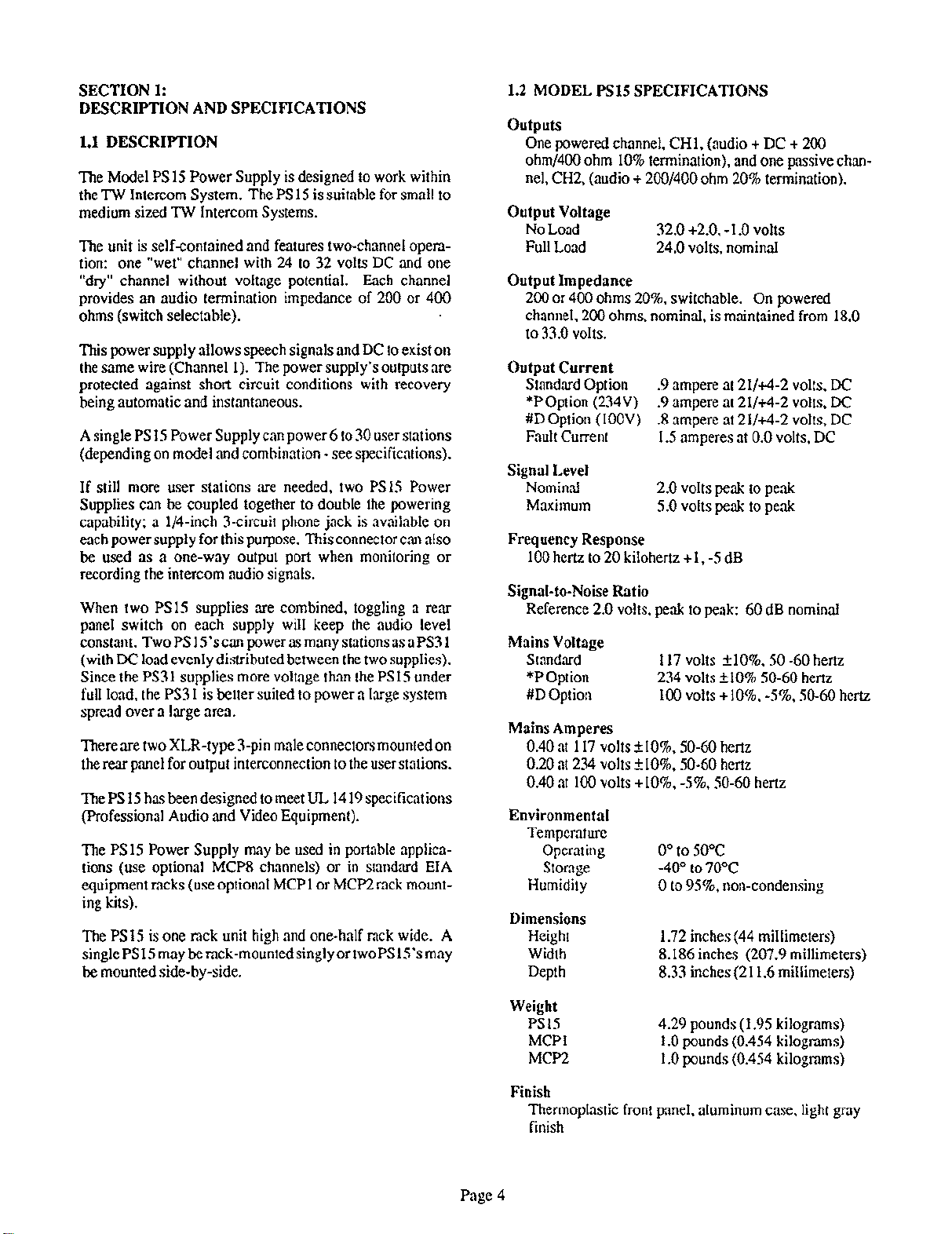
designed to accept A3F 3-pin female connectors. Thefirst table on the nextpageshowsoperating distances
versusmodel numbersfor the PS15power supply. The
second table on the next page shows the maximum
number of user stationsthat the PS15can sustain. For
combinations of stations, multiply the current values in
the first table timesthe number of units of that type. The
sumof all the currents should be lessthan 1 ampere for
thePS15.
2.3 POWER and INPUT POWER SELECTION
2.5 TANDEM OPERATION
Two Model PS15 power supplies can be used in tandem to
double the number of stations that can be powered. First,
the stations are divided between the supplies. Then, a
stereopatch cord is plugged into the stereojack on the rear
panel of each supply. The DUAL/NORMAL switch is set
to DUAL. This switch corrects the halving of the
impedance of two supplies in parallel by doubling the
impedanceof eachsupply from 200 to 400 ohms. The line
signal levels are maintained because the net impedance is
now 200 ohms.
The power cord is attached to the rear panel. Power
selection is normally done at the factory. If field change
of the input mains voltage is required, disconnect the
power, open the case, and set jumpers as follows (using
layout diagram on page 10):
For 117 VAC operation, T1 is Signal Transformer
LP56-425 or equivalent; install W1, W2, W4, and W6,
remove W3 and W5. * (Standard-American ]
For 234 VAC operation, T1 is Signal Transformer
LP56-425 or equivalent; install W3, W4, and W6,
remove W1, W2, and W5. * [*P Option-European]
For 100 VAC operation, TI is Signal Transformer
LP30-800 or equivalent: install Wl, W2, and W5,
remove W3, W4, and W6. ** [#D Option-Japanese)
The fuse must aJsobe changed to the rating shown on the
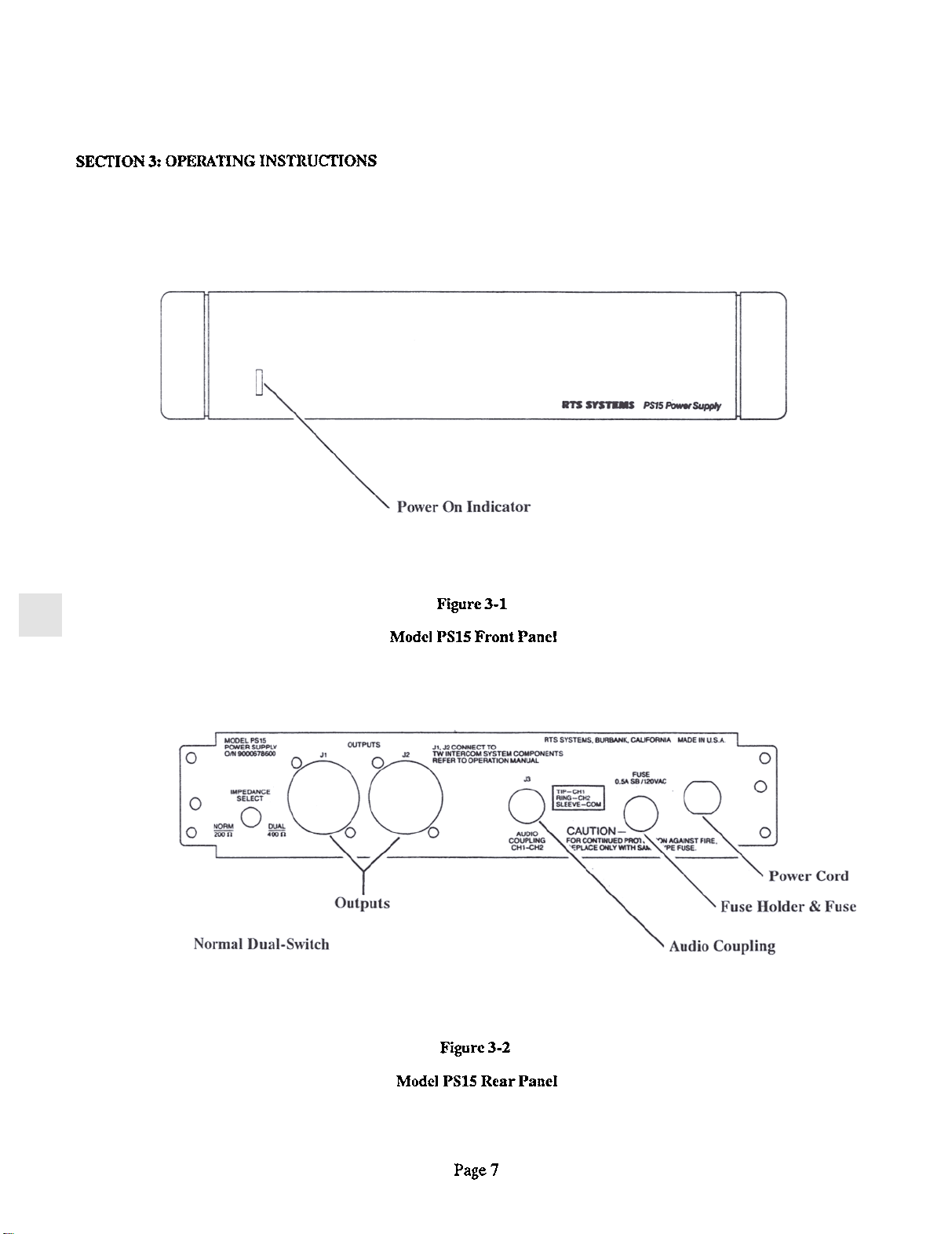
rear panel. 2.6 AUDIO OUTPUT I INPUT
The AUDIO COUPLING CHI-CH2 jack on the rear panel
provides an unbuffered, unbalanced audio output for each
of the two channels. The level ranges from
-10 dBu to 0 dBu. An isolation transformer is
recommended to prevent a ground loop between the
intercom system common and other grounds.
.Transformer LP56-425 is a dual primary, dual secondary
transformer. The primaries are 115 volts each. The two
secondaries are rated 28 volts at 850 milliamperes when
connected in parallel. For 115 volt operation, the
primaries are in parallel, and the secondaries are in
parallel. For 230 volt operation, the primaries are in
series, and the secondaries are in parallel. The AUDIO COUPLING jack may also be used to input a
signal into the system. Use at least a 2.2 kilohm resistor in
serieswith the signal source to prevent loading of the RTS
Systemsintercom line. Use an audio isolation tranformer
to prevent ground loops.
..Transformer LP30-800 is a dual primary, dual
secondary transformer. The primaries are normally rated
115 volts each, but jn this case will be operated at 100
volts each. The secondaries are normally rated at 30 volts
Page 5