SurfPrep SPPV15-A/E User manual

September 2019
WARNING
SAFETY LEGEND
• A HEPA Filter must be installed in this vacuum at all times
• If this vacuum is used to collect hazardous material, personal protective equipment should be used when opening the vacuum or
emptying its contents
• If this vacuum is intended for Dust Ignition Proof Operation, it must be used with supplied or recommended accessories from
SurfPrep Associates
• Any alteration to this equipment by a third party will nullify its warranty
Hearing protection is recommended
when operating this equipment.
Respiratory protection is recommend-
ed when operating this equipment.
Read and understand operator’s man-
ual before using this equipment.
Eye protection is required when oper-
ating this equipment.
WARNING WARNING
WARNING
WARNING
Safety – Operation – Maintenance
Keep this document in a safe place
Read and understand this manual before operating your vacuum
SurfPrep Vacuum System
120V with Electric/Pneumatic Tool Sync
Model: SPPV15-A/E
• Designed for general cleanup, housekeeping, vacuum sanding
• Dry Recovery Only

IMPORTANT SAFETY INSTRUCTIONS
READ ALL INSTRUCTIONS BEFORE USING THIS APPLIANCE
When using an electrical appliance, basic precautions should always be followed, including the following:
WARNING
• To reduce the risk of fire, electric shock, or injury:
• Do not leave appliance when plugged in. Unplug from outlet when not in use and before servicing.
• This unit is to be used only indoors and in a dry location.
• Use only as described in this manual. Use only manufacturer’s recommended attachments.
• Do not use with damaged cord or plug. If appliance is not working as it should, has been dropped, damaged, left outdoors,
or dropped into water, return it to a service center.
• Handle provided on power head is used only for removal of power head during maintenance.
• Before separation of power head from tank, users must disengage draw latches on tank.
• Do not pull or carry by cord, use cord as a handle, close a door on cord, or pull cord around sharp edges or corners.
• Do not run appliance over cord. Keep cord away from heated surfaces.
• Do not unplug by pulling on cord. To unplug, grasp the plug, not the cord.
• Do not handle plug or appliance with wet hands.
• Do not put any object into openings. Do not use with any opening blocked; keep free of dust, lint, hair, and anything that may
reduce air flow.
• Keep hair, loose clothing, fingers, and all parts of body away from openings and moving parts.
• Turn off all controls before unplugging.
• Do not use to pick up flammable or combustible liquids, such as gasoline, or use in areas where they may be present.
• Connect to a properly grounded outlet only. See Grounding Instructions.
• Do not pick up anything that is burning or smoking, such as cigarettes, matches, or hot ashes.
• Do not use without all filters in place.
• Do not allow to be used as a toy. Close attention necessary when used by or near children.
SAVE THESE INSTRUCTIONS
EARTHING/GROUNDING INSTRUCTIONS
This appliance must be earthed/grounded. If it should malfunction or breakdown, earthing/grounding provides a path of least
resistance for electric current to reduce the risk of electric shock. This appliance is equipped with a cord having an equipment-
earthing/grounding conductor and earthing/grounding plug. The plug must be inserted into an appropriate outlet that is properly
installed and earthed/grounded in accordance with all local codes and ordinances.
WARNING – Improper connection of the equipment-earthing/grounding conductor can result in a risk of electric shock. Check with
a qualified electrician or service person if you are in doubt as to whether the outlet is properly earthed/grounded. Do not modify
the plug provided with the appliance – if it will not fit the outlet, have a
proper outlet installed by a qualified electrician.
See Power Head Name Plate for electrical requirements
USA 120V
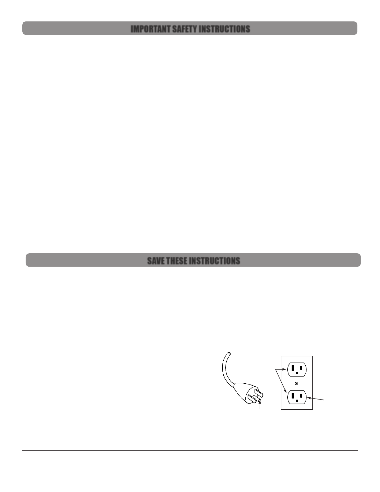
This appliance has a earthing/grounding attachment plug
that looks like the plug illustrated in Figure 1. Make sure that the
appliance is connected to an outlet having the same configuration as
the plug. No adapter should be used with this appliance.
International 120V
This appliance has a IEC 60309 125V earthing/grounding attachment
plug. Make sure that the appliance is connected to an outlet having the
same configuration as the plug. No adapter should be used with this
appliance
Earthed/Grounded
Outlet
Repair or Warranty Contact SurfPrep •571 Birch Street •Lake Elsinore, CA 92530 •P.+1-951-245-4200 F.+1-951-245-4299
www.SurfPrepSanding.com
Page 2
Figure 1: Earthed/Grounded Outlet and Plug
Earthed/Grounded
Outlet Box

TABLE OF CONTENTS
APPLICATIONS & ENVIRONMENTS
• Designed for general cleanup and housekeeping
• Dry Recovery Only
Do not use this equipment for cleaning or extracting fuel residues from any vehicle or equipment
Do not use this equipment for cleaning or extracting live sparks or burning embers
WARNING
Important Safety Instructions ............................................................................. 2
Save These Instructions...................................................................................... 2
Table of Contents .............................................................................................. 3
Applications & Environments ............................................................................. 3
What’s Included................................................................................................. 4
Specifications & Requirements........................................................................... 4
Getting Started ................................................................................................. 4
Compressed Air Fittings..................................................................................... 5
Pneumatic Tool Sync.......................................................................................... 6
Electric Tool Sync .............................................................................................. 7
Before Each Use ................................................................................................8
Bag Filter Change.............................................................................................. 9
Pre-Filter Change .............................................................................................10
HEPA Filter Change..........................................................................................10
Illustrated Parts Breakdown................................................................................11
20 Year Limited Warranty Terms and Conditions................................................15
Repair or Warranty Contact SurfPrep •571 Birch Street •Lake Elsinore, CA 92530 •P.+1-951-245-4200 F.+1-951-245-4299
www.SurfPrepSanding.com
Page 3

Repair or Warranty Contact SurfPrep •571 Birch Street •Lake Elsinore, CA 92530 •P.+1-951-245-4200 F.+1-951-245-4299
www.SurfPrepSanding.com
Page 4
WHAT’S INCLUDED
GETTING STARTED
1. The Vacuum Power Head and the Vacuum Tank ship in separate boxes
2. Unbox the Vacuum Power Head
3. Visually inspect Power Head to ensure that no parts are missing or damaged
4. Familiarize yourself with the Power Head
Power Cord
Filter Adapter
Pneumatic
Tool Sync Gauge
Pneumatic
Tool Sync Adjustment
Compressed Air Plug
(Air In)
HEPA Wire Lock
Hex Stando
HEPA Wire Lock
Hex Stando
Power Switch
Compressed
Air Coupler
(Tool Air Out)
125V
(Tool Power Out)
Compressed
Air Coupler
(Tool Air Out)
125V
(Tool Power Out)
SurfPrep Power Heads ship with the following items:
• SurfPrep Power Head
• HEPA 12 Month Timer Card
SurfPrep Vacuum Tanks ship separately and include
Bags, Filters, and other components.
These instructions
assume you have both a Power Head and one of
the following SurfPrep Vacuum Tanks
SPECIFICATIONS & REQUIREMENTS
Weight ............................................................................................................. 21.7 lbs (9.8 kg)
Dimensions............................................................. 17.5 x 17.5 x 12 in (44.5 x 44.5 x 30.5 cm)
HEPA Filter Eciency....................................................................... 99.995% @ 0.3 μm (H14)
Filter Bag Eciency......................................................................................95% @ 0.5 micron
Sounds Pressure Level ................................................................................................<70 dBA
Compressed Air Consumption.................................................................... Determined by Tool
Compressed Air Supply Pressure..................................................... 90-120 PSI (6.2 - 8.3 bar)
Power Consumption .........................................................................................120VAC~ 14.5A
Vacuum Flow ..........................................................................................120 CFM (204 SCMH)
Vacuum Suction......................................................................................... 120 in/H
2
O (30 kPa)

COMPRESSED AIR FITTINGS
The vacuum has the following Compressed Air Requirements to function properly.
• Compressed air must be clean, dry, and oil free to prevent blockage of the pneumatic system
• Compressed air line and ttings must have a minimum diameter of 1/4in (7mm)
Compressed Air Plug (air in)
• The Vacuum is supplied with a 1/4in (7mm) industrial interchange compressed air plug for connection to your compressed air supply
The Compressed Air Plug may be changed to another nominal 1/4in (7mm) style if required.
• Hold the brass bulkhead tting with a 1in (26mm) open end wrench
• Remove the compressed air plug with either a 9/16in (15mm)deep socket or 9/16in (15mm)open end wrench
• Install a new compressed air plug
Compressed Air Coupler (air out)
• The Vacuum is supplied with two 1/4in (7mm) brass high ow compatible industrial interchange compressed air couplers
• This coupler provides convenient pass through compressed air for an air tool connected to the vacuum
The Compressed Air Coupler may be changed to another nominal 1/4in (7mm) style if required.
• Hold the brass bulkhead tting with a 1in (26mm) open end wrench
• Remove the compressed air coupler with a 3/4in (19mm) open end wrench
• Install a new compressed air coupler
WARNING
Repair or Warranty Contact SurfPrep •571 Birch Street •Lake Elsinore, CA 92530 •P.+1-951-245-4200 F.+1-951-245-4299
www.SurfPrepSanding.com
Page 5
5. Power Head Vents
• NEVER BLOCK THE POWER HEAD VENTS
• NEVER WRAP THE POWER CORD AROUND THE POWER HEAD VENTS
GETTING STARTED
Vents
Preparing the Vacuum for Use
1. Install a Filter Bag
• Unfold and u a new Filter Bag
• Push the inlet tube into the hole on the cardboard collar of the Filter Bag
• Grasp the sides of the cardboard collar and push it all the way on to the inlet tube
• Ensure the bottom of the collar is past the opening on the underside of the inlet tube
2. Unbox a new HEPA Filter
• Remove the HEPA Timer Card from the box and set aside
• Remove the HEPA Cable Lock from the box and set aside
• Remove the HEPA Filter from the box and remove from plastic bag
3. Install a new HEPA Filter
• Holding the power head on its side, screw the new HEPA Filter onto the threaded nipple
• Ensure the white inner ring of the HEPA Filter is in contact with the underside of the power head
• If it is not, turn it clockwise until it comes in contact with the underside of the power head
• See the instructions included with the HEPA Cable Lock
4. Attach the Power Head
• Sit the Power Head on the tank
• Rotate the Power Head so that the switch on the Power Head is in line with the inlet port on the vacuum tank
• Latch the Power Head to the tank

PNEUMATIC TOOL SYNC
1. Principle of Operation
Pneumatic tool sync senses the ow of compressed air to a connected tool and activates the vacuum
• When the compressed air tool is activated, the compressed air line pressure closes a pneumatic electric relay which activates the
power head
• The auto system pressure in the relay is approximately 90 psi while the tool is running
• When the compressed air tool is deactivated the pressure will bleed down to 0 psi, at a rate based on the adjustment of the Shuto
Delay Valve
• When the tool sync pressure reaches approximately 15 psi the relay opens and deactivates the power head
• The tool sync pressure gauge helps the user visualize the time delay by displaying the pressure in the pneumatic electric relay as it
changes from 90 psi to 0 psi
2. Requirements
• A compressed air supply must be connected to the compressed air in plug on the power head
• The tool must draw its compressed air from the compressed air out coupler on the power head
• Compressed air must be clean, dry, and oil free to prevent blockage of the pneumatic system
• Compressed air line and ttings must have a minimum diameter of 1/4in
3. Attach the Compressed Air Line
• Ensure that the power switch on the vacuum is in the o position
• Connect the compressed air line to a compressed air source
• Connect the compressed air line to the compressed air in plug on the vacuum
4. Attach the Compressed Air Tool
• Ensure that the power switch on the vacuum is in the o position
• Connect the tool compressed air line to the compressed air out coupler on the power head
• Connect the tool compressed air line to the compressed air plug on the tool
5. Testing Pneumatic Tool Sync
• Toggle the power switch to the Auto position
• Activate the air tool
• The power head will activate
• Deactivate the air tool
• The vacuum will deactivate after a short delay
6. Adjusting the Pneumatic Tool Sync Shuto Delay
The Shuto Delay is factory set to approximately 5 sec
• Loosen the jam nut
• Turn the Shuto Delay valve clockwise until it stops.
• Toggle the power switch to the Auto position.
• Activate the air tool
• The vacuum will power on
• Deactivate the air tool
• The vacuum will remain running
• Slowly turn the Shuto Delay valve counterclockwise until the Tool Sync Pressure Gauge begins to drop
• When the Tool Sync Pressure reaches approximately 15 psi the relay opens and deactivates the power head
• Continue to test Pneumatic Tool Sync by activating the compressed air tool
• Adjust the Shuto Delay Valve until the pressure bleeds down as slow or as fast as required using the tool sync pressure gauge
as a guide
7. Multiple Tools
• Pneumatic Tool Sync will work with one or two tools simultaneously
• Pneumatic Tool Sync will work in conjunction with Electric Tool Sync
Repair or Warranty Contact SurfPrep •571 Birch Street •Lake Elsinore, CA 92530 •P.+1-951-245-4200 F.+1-951-245-4299
www.SurfPrepSanding.com
Page 6

ELECTRIC TOOL SYNC
1. Principle of Operation
Electric tool sync senses the amp draw from a connected tool and activates the vacuum
• When the electric tool is activated, an electric relay closes which activates the power head
• When the electric tool is deactivated a timer keeps the vacuum running for approximately 10 secs and then deactivates the power head
2. Requirements
• The tool must draw it’s power from the outlets on the power head
3. Connect the vacuum to a 125V power source
• Ensure that the power switch on the vacuum is in the o position
• Connect the vacuum to a 125V power source
4. Attach the Electric Tool
• Ensure that the power switch on the vacuum is in the o position
• Connect the electric tool to the electric outlet on the power head
5. Testing Electric Tool Sync
• Toggle the power switch to the Auto position
• Activate the electric tool
• The power head will activate
• Deactivate the electric tool
• The vacuum will deactivate after a short delay
6. Multiple Tools
• Electric Tool Sync will work with one or two tools simultaneously
• Electric Tool Sync will work in conjunction with Pneumatic Tool Sync
7. Electronic Tools
• Each time a tool draws power the vacuum head may activate. Some electronic tools may draw power when initially connected, to light
LEDs, when powered up, AND when activated. This may trigger the vacuum multiple times and is expected.
Repair or Warranty Contact SurfPrep •571 Birch Street •Lake Elsinore, CA 92530 •P.+1-951-245-4200 F.+1-951-245-4299
www.SurfPrepSanding.com
Page 7

Repair or Warranty Contact SurfPrep •571 Birch Street •Lake Elsinore, CA 92530 •P.+1-951-245-4200 F.+1-951-245-4299
www.SurfPrepSanding.com
Page 8
BEFORE EACH USE
1. Attach the Vacuum Hose (optional)
• Open the Vacuum Inlet
• Insert the metal sleeve of the vacuum hose into the inlet on the vacuum
2. Attach a Combination Air/Vac Hose (optional)
• Open the Vacuum Inlet
• Insert the metal sleeve of the vacuum hose into the inlet on the vacuum
• Connect the compressed air line to the compressed air coupler on the vacuum
3. Attach the Compressed Air Line (optional)
• Ensure that the power switch on the vacuum is in the o position
• Connect the compressed air line to a compressed air source
• Connect the compressed air line to the compressed air plug on the vacuum
4. Activating the Vacuum
Pneumatic Tool Sync Mode
This vacuum is equipped with Pneumatic Tool Sync (Auto Mode) which activates the vacuum automatically
when a compressed air tool is activated.
The pass through compressed air connection is required for Pneumatic Tool Sync operation.
• Toggle the Power Switch to the Auto Position for Pneumatic Tool Sync
Electric Tool Sync Mode
This vacuum is equipped with Electric Tool Sync (Auto Mode) which activates the vacuum automatically when
an electric tool is activated.
The tool must draw it’s power from the outlets on the power head.
• Toggle the Power Switch to the Auto Position for Electric Tool Sync
Manual On/O Mode
This vacuum is equipped with Manual Mode (ON Mode) which activates the vacuum when the switch is
set to ON
• Toggle the Power Switch to the ON Position

BAG FILTER CHANGE
If this vacuum is used to collect hazardous material, appropriate personal protective equipment may be required.
The bag lter should be replaced then ¾ full
1. Safe the Vacuum
• Disconnect the Vacuum from power source
2. Remove the Power Head
• Unlatch the Power Head from the tank
• Lift the Power Head and attached HEPA lter o the tank by the top handle
• Carefully sit the Power Head on the oor - avoid damaging the HEPA lter
3. Remove the Filter Bag
• Grasp the cardboard collar of the bag lter and slide it o the inlet
• Holding your hand over the opening on the bag, lift the bag out of the tank
• Dispose of the bag according to your company policy
4. Install a Filter Bag
• Unfold and u a new Filter Bag
• Push the inlet tube into the hole on the cardboard collar of the lter bag
• Grasp the sides of the cardboard collar and push it all the way on to the inlet tube
• Ensure the bottom of the collar is past the opening on the underside of the inlet tube
5. Ensure the HEPA Filter is sealed
• Holding the power head on its side, look at the HEPA Filter
• Ensure the white inner ring of the HEPA Filter is in contact with the underside of the power head
• If it is not, turn it clockwise until it comes in contact with the underside of the power head
6. Replace the Power Head
• Sit the Power Head on the tank
• Rotate the Power Head so that the switch on the Power Head is in line with the inlet port on the vacuum tank
• Latch the Power Head to the tank
Repair or Warranty Contact SurfPrep •571 Birch Street •Lake Elsinore, CA 92530 •P.+1-951-245-4200 F.+1-951-245-4299
www.SurfPrepSanding.com
Page 9

HEPA FILTER CHANGE
If this vacuum is used to collect hazardous material, appropriate personal protective equipment may be required.
The HEPA lter should be replaced when it is damaged, clogged, or when the HEPA timer card has reached
12 months.
1. Safe the Vacuum
• Disconnect the Vacuum from power source
2. Remove the Power Head
• Unlatch the Power Head from the tank
• Lift the Power Head and attached HEPA lter o the tank by the top handle
• Carefully sit the Power Head on the oor - avoid damaging the HEPA lter
3. Unbox a new HEPA Filter
• Remove the HEPA Timer Card from the box and set aside
• Remove the HEPA Cable Lock from the box and set aside
• Remove the HEPA Filter from the box and remove from plastic bag
4. Remove the HEPA Filter
• Holding the Power Head on its side cut the HEPA Cable Lock and remove
• Unscrew the HEPA Filter
• Dispose of the HEPA Filter according to your company policy
5. Install a new HEPA Filter
• Holding the power head on its side, screw the new HEPA Filter onto the threaded nipple
• Ensure the white inner ring of the HEPA Filter is in contact with the underside of the power head
• If it is not, turn it clockwise until it comes in contact with the underside of the power head
• See the instructions included with the HEPA Cable Lock
6. Replace the Power Head
• Sit the Power Head on the tank
• Rotate the Power Head so that the switch on the Power Head is in line with the inlet port on the vacuum tank
• Latch the Power Head to the tank
7. Activate the HEPA Filter Timer
• Remove the old HEPA timer card from the power head
• Attach the new HEPA timer card with a zip tie (included) to the top handle of the vacuum
• Follow the directions on Timer Card to activate
PRE-FILTER CHANGE
If this vacuum is used to collect hazardous material, appropriate personal protective equipment may be required.
The pre-lter should be replaced if clogged or visibly dirty
1. Safe the Vacuum
• Disconnect the vacuum from power source
2. Remove the Power Head
• Unlatch the Power Head from the tank
• Lift the Power Head and attached HEPA lter o the tank by the top handle
• Carefully sit the Power Head on the oor - avoid damaging the HEPA lter
3. Remove the Pre-Filter
• The Pre-Filter is wrapped around the HEPA lter and secured with Velcro
• Find the seam and carefully peel the Velcro apart
• Dispose of the Pre-Filter according to your company policy
4. Install a new Pre-Filter
• Unfold a new Pre-Filter and remove the thin Velcro cover strip from the Velcro hooks
• Wrap the Pre-Filter tightly around the HEPA lter
• Secure the Pre-Filter by adhering the Velcro hooks to the side of the Pre-Filter
Repair or Warranty Contact SurfPrep •571 Birch Street •Lake Elsinore, CA 92530 •P.+1-951-245-4200 F.+1-951-245-4299
www.SurfPrepSanding.com
Page 10

ILLUSTRATED PARTS BREAKDOWN
SP-603-WGC-0
SEQ ITEM NO DESCRIPTION
1 SP-600-A108-120 MOTOR ASSEMBLY 120V
2 SP-600-WF-1364F WASHER FIBER 13/64 ID X 3/8OD
3 SP-6601-021 FILTER ADAPTER,
4 SP-6601-121 MESH DISC, 3 IN DIAMETER
5 SP-6605-310B16 HH VAC HEAD BASE 16IN SS BLACK
6 SP-6911-011 GASKET, FILTER ADAPTER
7 SP-6911-Q6600-220T CONICAL MOTOR GASKET SILICA GEL
8 SP-6FE103208-HZSM-B HEX STANDOFF, 10-32 MF X 1/2 SS WITH BORE
9 SP-6NE10320608-HNSZ NUT 10-32 NYLON LOCK SS SHORT
10 SP-6NE16201420-HNSZ NUT 1/4-20 HEX LOCK SS
11 SP-6SE162005-PPSM-Z SCREW, 1/4-20 X 5/16 PH, SS
12 SP-6SE162064-HHSM-Z SCREW 1/4-20 X 4IN SS HEX
SP-603-WGC-0
SEQ ITEM NO DESCRIPTION
13 SP-6600-Q6600-220T MOTOR BYPASS 120V 13.5A 2HP 120CFM
14 SP-6605-310C HH VAC HEAD MOTOR COLLAR SS
15 SP-6911-04G08 GROMMET 7/32 ID, 1/2 OD
16 SP-6
911-803-5 MOTOR PLATE SOUND CONTROL FOAM
17 SP-6SE101212-PPSS-Z SCREW, SHEET METAL, #10 X .750, PHILLIPS, SS
18 SP-6WE133203-RFS-Z WASHER .203ID X .500OD .047H ROUND STAINLESS STEEL
Repair or Warranty Contact SurfPrep •571 Birch Street •Lake Elsinore, CA 92530 •P.+1-951-245-4200 F.+1-951-245-4299
www.SurfPrepSanding.com
Page 11
10
1
16
17
15
13
18
14
7
11
4
5
12
8
2
9
3
6

ILLUSTRATED PARTS BREAKDOWN
603-WGC-0
SEQ ITEM NO DESCRIPTION
1 SP-6150-033 OUTLET, PANEL MOUNT NEMA 5-15R
2 SP-6350-023 STRAIN RELIEF FOR 20 AMP CORD
3 SP-6605-310A HH VAC HEAD HANDLE CAP SS BLACK
4 SP-6605-310D HH VAC HEAD EXHAUST BAFFLE SS BLACK
5 SP-6605-312E WGC VAC ENCLOSURE AUTO-COMBO 120V SS BLK
6 SP-6900-123N520P-25 CORD 12/3 20A CORD LOCK PLUG 25FT YEL
7 SP-6900-M12R3 MOLEX RECEPTACLE, 12 GA, 3 POSITION
8 SP-6900-M12S MOLEX SOCKET TERMINAL, 12 GA
9 SP-6900-SW-SPDT-01 SWITCH ROCKER RECT 20A 120V SPDT ON-OFF-ON BLACK
10 SP-6918-04BH BULKHEAD ADAPTER, BRASS, 1/4IN.
11 SP-6924-04CV CHECK VALVE, 1/4 MNPT
12 SP-6930-027 HANDLE, CARRY, FLEX RUBBER
13 SP-6940-011 FITTING COUPLER 1/4IN HIFLOW X 1/4 MNPT
14 SP-6940-016 FITTING PLUG 1/4IN HIFLOW X 1/4IN MNPT
15 SP-6FE103212-HZSM-Z HEX STANDOFF, 10-32 MF X 3/4 IN SS
16 SP-6NE10320608-HNSZ NUT 10-32 NYLON LOCK SS SHORT
17 SP-6RE0620-SDSSS-Z RIVET BLIND 3/16 X 0.625 SEALED SS (.251-.375)
18 SP-6SE103206-XPSM-Z SCREW 10-32 X 3/8IN SS TORX
19 SP-6WE133203-RFS-Z WASHER .203ID X .500OD .047H ROUND STAINLESS STEEL
20 SP-6WE481803-RZSZ SHIM .750 ID X 1.125 OD X .048 ROUND STAINLESS
Repair or Warranty Contact SurfPrep •571 Birch Street •Lake Elsinore, CA 92530 •P.+1-951-245-4200 F.+1-951-245-4299
www.SurfPrepSanding.com
Page 12
4
2
6
8
7
5
1
9
3
15
14
10
16
11
10
13
20
15
18
19
12
17

ILLUSTRATED PARTS BREAKDOWN
603-WGC-0
SEQ ITEM NO DESCRIPTION
1 SP-6911-803-1 HANDLE CAP SOUND CONTROL FOAM
2 SP-6911-803-2 EXHAUST BAFFLE SOUND CONTROL FOAM
3 SP-6911-803-3 ENCLOSURE TOP SOUND CONTROL FOAM
4 SP-6911-803-4 BASE RING SOUND CONTROL FOAM
5 SP-6911-803-6 ENCLOSURE FOAM 1 SOUND CONTROL
5 SP-6911-803-7 ENCLOSURE FOAM 2 SOUND CONTROL
5 SP-6911-803-8 ENCLOSURE FOAM 3 SOUND CONTROL
Repair or Warranty Contact SurfPrep •571 Birch Street •Lake Elsinore, CA 92530 •P.+1-951-245-4200 F.+1-951-245-4299
www.SurfPrepSanding.com
Page 13
1
2
3
4
5

ILLUSTRATED PARTS BREAKDOWN
603-WGC-0
SEQ ITEM NO DESCRIPTION
1 SP-6600-A276T AUTO SYSTEM FLOW SENSOR VALVE THREADED
2 SP-6900-033 FASTON CAP .187 TAB
3 SP-6900-SW-SPST-03 SWITCH PNEUMATIC RELAY 100PSI 15A 120V
4 SP-6922-T.25GN 1/4 IN OD. NYLON TUBING GREEN
5 SP-6922-T.50BK TUBING, 1/2 OD, HIGH TEMP PER FT
6 SP-6924-04FC-01 ALPHA FLOW CONTROL VALVE
7 SP-6925-P24R160-01 GAUGE PRESSURE 1.5IN 0-160 PSI PANEL MOUNT
8 SP-6927-04FA-02 FEMALE ADAPT, 1/4 PC X 1/8 FNPT
9 SP-6927-04L-02 PC ELBOW 1/8 MNPT X 1/4 TUBE
10 SP-6927-04L-02F FTG ELBOW 1/8 FNPT TO 1/4 PC
11 SP-6927-04T TEE, 1/4 PC
12 SP-6927-08L-04 FTG ELBOW 1/2 PC TO 1/4 MNPT
13 SP-6927-08L-04F FTG ELBOW 1/2PC TO 1/4FNPT
14 SP-6927-08MA-04 1/2 PC X 1/4 MPT STRAIGHT FTG
15 SP-6927-08Y UNION Y, 1/2PC
Repair or Warranty Contact SurfPrep •571 Birch Street •Lake Elsinore, CA 92530 •P.+1-951-245-4200 F.+1-951-245-4299
www.SurfPrepSanding.com
Page 14
15
12
10
12
13
13
14
11
5
1
4
8
4
7
3
2
9
9
6
9

20 YEAR LIMITED WARRANTY TERMS AND CONDITIONS
Warranty Terms
SurfPrep guarantees its manufactured products against defects in materials or workmanship and will either repair or replace all
parts that prove defective under normal use during the limited warranty time of the products. The warranty period shall commence
from the date of paid invoice.
This warranty does not cover (a) repairs due to normal wear, accident, neglect, misuse, or use other than as indicated in the
instruction booklet (b) products manufactured by third parties and distributed by SurfPrep (c) wear items such as bearings, rotor
blades, regulators,
valve stems, levers, shrouds, guards, O-rings, seals, gaskets, motor brushes, and other wearable parts.
Repair within the Continental US
During the first 90 days of the warranty period, SurfPrep will provide parts and labor to the customer’s site at no charge or pay
freight
costs associated with returning the products for repair to a SurfPrep selected service location and repair the product at no charge.
SurfPrep personnel will determine the best way to repair the product.
Past 90 days, SurfPrep will provide parts to the customer’s site at no charge or the customer may ship the product to a SurfPrep
selected service location at customer’s expense and SurfPrep will repair the product at no charge and provide return shipping.
Repair Outside the Continental US
SurfPrep will provide parts to the customer’s site at no charge or the customer may ship the product to a SurfPrep selected service
location at customer’s expense and SurfPrep will repair the product at no charge and provide return shipping.
Limitation of Liability
SurfPrep shall not in any event be liable for any damages, loss of production time or profits, whether based on contract, warranty,
negligence, strict liability or otherwise, including without limitation any consequential, incidental or special damages, arising with
respect to the equipment or its failure to operate.
SurfPrep makes no other warranty or representation of any kind, except that of title, and all other warranties,
express or implied, including warranties of merchantability or fitness for any particular purpose, are hereby expressly disclaimed.
Repair or Warranty Contact SurfPrep •571 Birch Street •Lake Elsinore, CA 92530 •P.+1-951-245-4200 F.+1-951-245-4299
www.SurfPrepSanding.com
Page 15

SurfPrep products are proudly made in the USA
Repair or Warranty Contact SurfPrep •571 Birch Street •Lake Elsinore, CA 92530 •P.+1-951-245-4200 F.+1-951-245-4299
www.SurfPrepSanding.com
Page 16
Table of contents
Other SurfPrep Vacuum Cleaner manuals