3ZZX419340E-05 2/10
Read Before Use
Before using this product, check the
compatibility of the type of liquid to use and
the wetted parts material in this product.
All users are required to carefully read and
understand this manual before operation of
the product.
Keep this manual in good condition and
close at hand for quick reference whenever
necessary.
Use the product only as intended, and only
as directed in this manual.
Cautionary notes in this manual must be
fully understood and complied with at all
times.
About This Operation Manual
The contents of this manual are subject to
change without prior notice, due to
improvements in product functionalities and
/ or performance.
No part of this manual may be reproduced
in any form or by any means.
Although this manual has been prepared
with all possible care, please do not hesitate
to contact Surpass Industry about errors,
omissions, or any other points of doubt.
Important Safety Instructions
<Symbols in This Operation Manual>
Warnings and cautionary notes are provided in this manual to ensure this product is used correctly and to
prevent personal injury and property damage. The meanings of the WARNING and CAUTION symbols in
this manual are as described below. Read and understand these notes before reading the rest of this
manual.
Specific Warnings
When mounting connector parts, comply with the
instructions issued by each connector manufacturer.
Loose connections may result in disconnection or
chemical leakage. The use of dangerous chemicals,
solvents, and gases may cause physical impairment.
Do not use the product in areas where corrosive gases are
being ejected. Corrosion in the pressure sensor and
connector may result in liquid leakage. The use of
dangerous chemicals, solvents, and gases may cause
physical impairment.
Obey these instructions.
- Refrain from excessive tightening of the connector parts.
- Do not install the product in areas of excessive vibration
or shock.
- Use the product only within the specified operating
environment. Otherwise, damage to the pressure sensor
and connector may occur and result in liquid leakage.
The use of dangerous chemicals, solvents, and gases
may cause physical impairment.
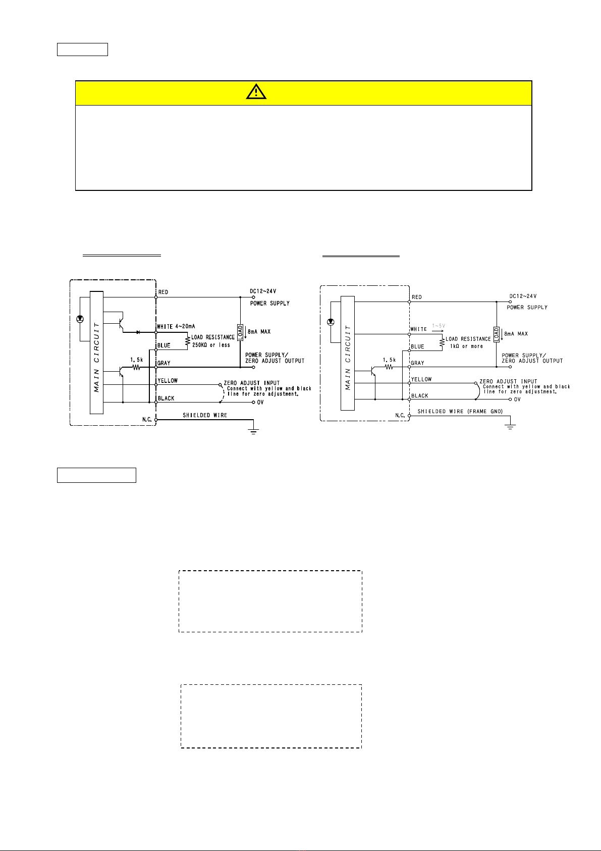
Protect all wiring used by providing support along the
wiring at appropriate distances.
For shielded cables, peel the sheath at the very end of the
cable and connect the shield to the chassis or mounting
plate, etc., using the proper tool (recommended tool: Nitto
Supply AL-2).
WARNING
This product is not explosion-proof. Never use it with
flammable fluids such as solvents. Doing so may cause
fire and or explosion and is highly dangerous.
Never disassemble or alter the product.
Doing so will cause breakage of the product and possible
liquid leakage. The use of dangerous chemicals, solvents,
and gases may cause physical impairment.
Do not apply more pressure than the allowed maximum
output. Doing so will cause product failure and possible
liquid leakage. The use of dangerous chemicals, solvents,
and gases may cause physical impairment.
Do not insert screwdrivers, wires, or other objects into the
connector parts. Doing so will cause product failure and
possible liquid leakage. The use of dangerous chemicals,
solvents, and gases may cause physical impairment.
Refrain from excessive pulling or bending of the cables.
Doing so may cause wiring disconnections, which may
cause electrical shock and fire hazards.
Install the pressure sensor in an area that is dry and
clean. Supply power to the pressure sensor from an
isolation transformer (switching power supply) rated for 24
VDC or less. Make sure the rated power output is 150 VA
and does not exceed 2A. (Use exclusively for class 2
circuits)
WARNING
This symbol indicates warnings against impending danger
which, if not observed, may cause death or severe injury to
the user.
DANGER
This symbol indicates warnings which, if not observed, may
cause death or severe injury to the user.
WARNING
This symbol indicates warnings which, if not observed, may
physically impair the user or damage surrounding objects.
CAUTION
Provides important notices and instructions for correct operation
of the product.