Sussman WarmaTowel W542 User guide

Warma
Towel
®
For Electric ModelsModel__________ Serial #________________
Table of Contents
_______________________
General Information & Specifications..... 1
Wall Preparation...................................... 2
Models W542, W552 & W554 .............. 3,4
Models W500 & W510.............................. 5
Model W556 ............................................. 6
Electrical Specifications............................ 7
Optional Programmable Timer................ 8
Warranty.............................................. 9,10
W500 W510
W542 W554 W552 W556
9B32 LISTED
IMPORTANT NOTE:
As you follow these instructions, you will notice warning and caution symbols. The symbols call
out information important for the safe and efficient installation and operation of your towel
warmer.
signals a situation where minor injury
or product damage may occur if you do
not follow instructions.
states a hazard may cause serious
injury or death if precautions are not
followed.
IMPORTANT NOTE:
This highlights information that is especially
relevant to a problem-free installation.
A Division of Sussman-Automatic Corporation
43-20 34th Street, Long Island City, NY 11101• (718) 937-4500
1-800 767-8326 • Fax: (718) 472-3256• www.mrsteam.com
Western Regional Offices
9410 S. La Cienega Blvd. Inglewood CA 90301
(310) 216-6565 • 1-800 727-8326 • Fax: (310) 216-2944
WARNING
!
CAUTION
!
PUR 103852 - 4/2001
Installation and Operating Instruction

WARMATOWEL is an electrical heating appliance, intended onl y for indoor residential applications
and, as such, should be installed and used with certain pr ecautions for your safety.
1. INSTALLATION PROCEDURES FOR PERMANENTLY-WIRED WALL-MOUNTE D UNITS MUST BE ACCOMPLISHED BY
QUALIFIED PERSONNEL IN STRICT ACCORD WITH APPLICABLE NAT IONAL AND LOCAL BUILDING AND ELECTRICAL CODES.
2. DO NOT place WARMATOWEL units inside a shower, sauna or s team room enclosure or any other wet location.
3. CAUTION is advised when WARMATOWEL is accessible to child ren.
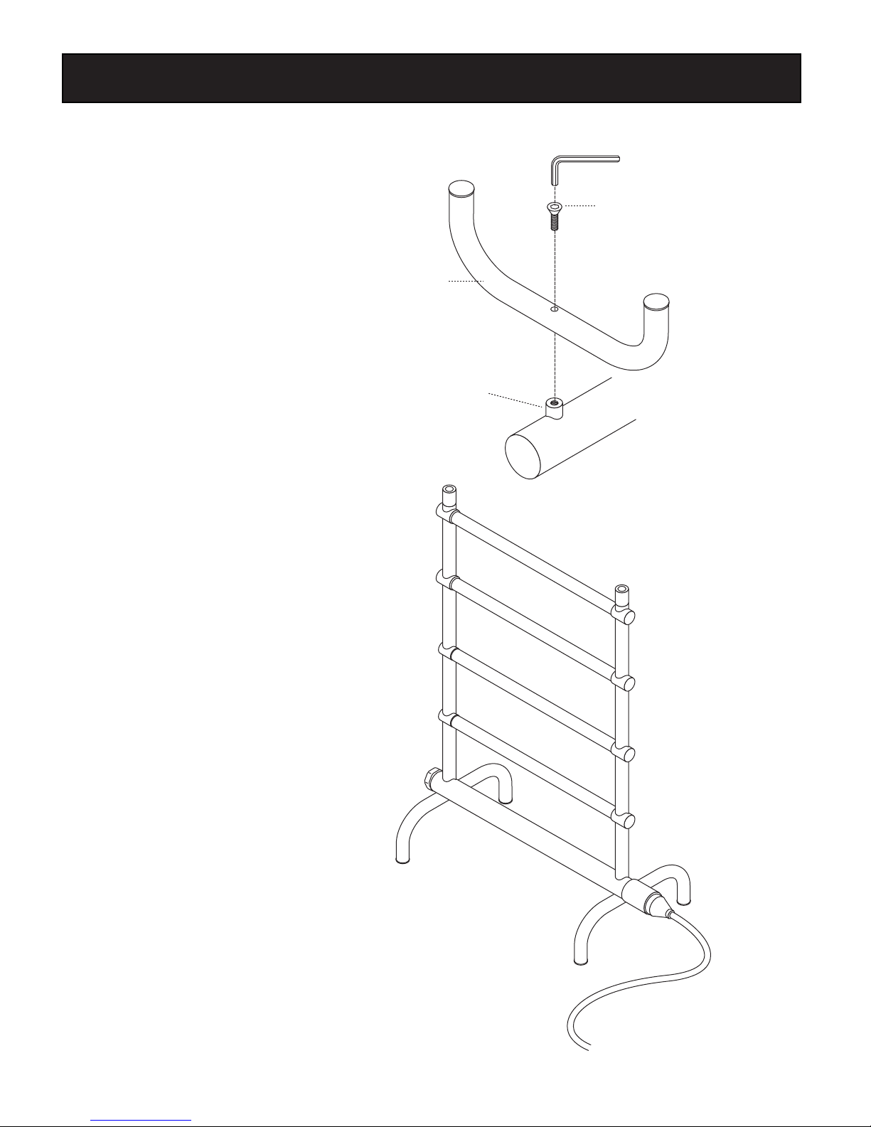
4. For the ultimate ease in use, a dedicated wall switch or timer can be used to control the WARMATOWEL unit.
Contact Sussman-Automatic Corp. for an in-wall 24-hour-7 da y timer (PN W-103588) Note: All switches and control
devices must be installed on the load (black) side of the Towel Warmer circuit in compliance with the National Electri c
Code and Local Codes. (see page 8 for installation instruc tions)
READ THIS ENTIRE INSTRUCTION MANUAL THOROUGHLY BEFORE BEGINN ING INSTALLATION AND SAVE THESE INSTRUCTIONS.
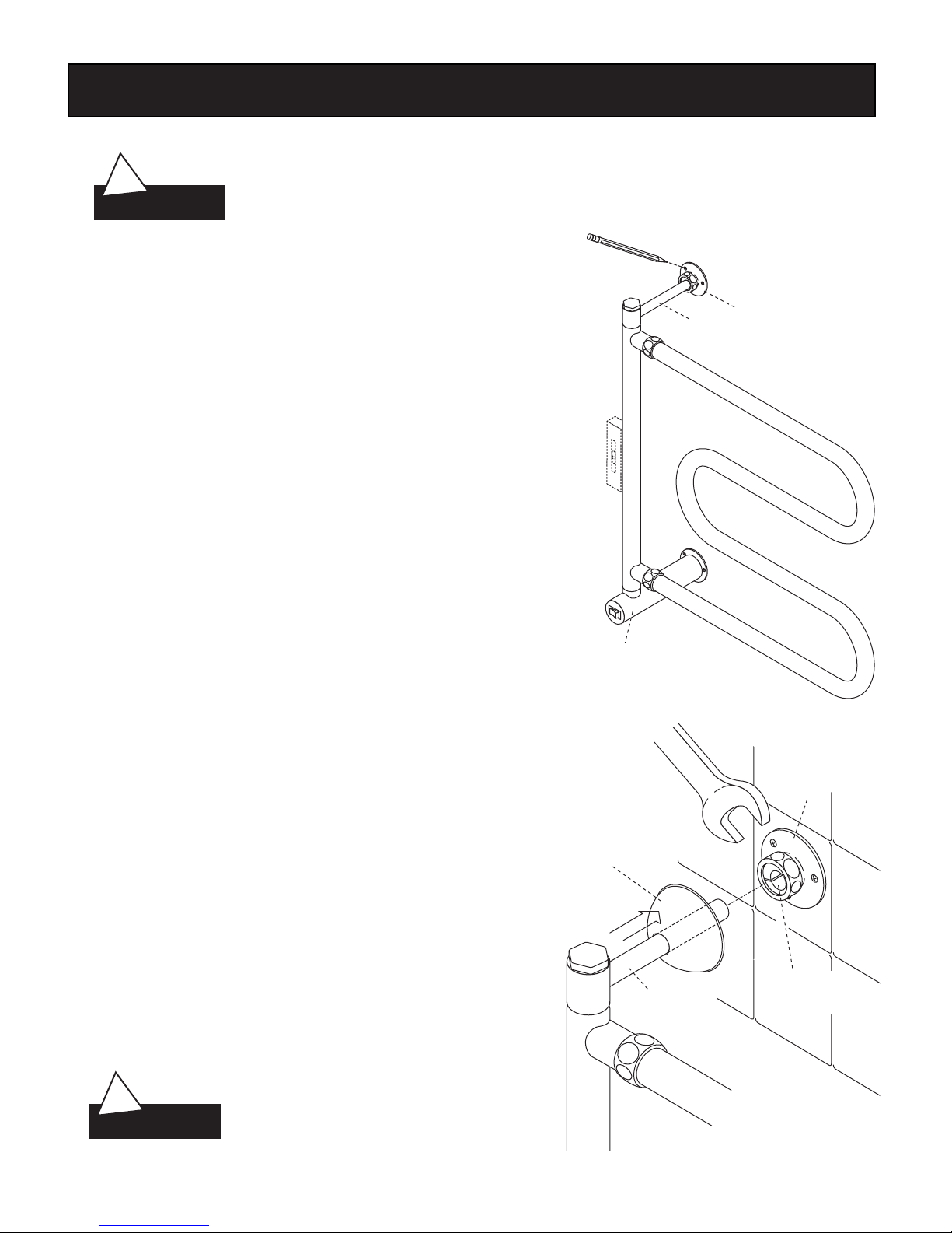
BE CERTAIN ELECTRICITY IS SHUT OFF AT MAIN PANEL BEFORE WIR ING OR SERVICING YOUR
WARMATOWEL. Follow instructions to make certain your WarmaT owel is properly attached
to the wall. FAILURE TO FOLLOW THESE STEPS COULD RESULT IN HAZARDOUS CONDITIONS.
To avoid possible fire hazard, the WarmaTowel must remain i n its intended position.
MOUNT THIS UNIT ONLY AS SHOWN IN THESE INSTRUCTIONS.
TO ENSURE CORRECT OPERATION OF YOUR WARMATOWEL, PLEASE FOLLO W ALL THE INSTRUCTIONS CAREFULLY,
OBSERVING THE "CAUTION" NOTATIONS FOR EACH STEP.
IMPORTANT:
The finish of your WarmaTowel can be protected and maintaine d by an occasional wiping with a soft,
non-abrasive, damp cloth and lightly polished, thereafter, w ith a soft dry cloth when the WarmaTowel is cold. Under no
circumstances should abrasive cleaning powders, metal polish or chlorine-based cleaners be used on any part of this prod uct.
IMPORTANT:
This appliance is intended for towels washed in water. Fabri cs that contain soap or detergent residue
may show what appears to be scorch marks. However this is si mply the discoloration of the residue. The WarmaTowel unit
does not reach sufficient temperature to scorch fabric.
We are not responsible for discoloring or scorching of any f abrics.
THANK YOU
for selecting WARMATOWEL, the perfect addition to bathrooms , family spas, and exercise rooms
within your home. Our products have long been a standard for quality and comfort, and we are sure that you will
experience continued enjoyment from the WARMATOWEL you have purchased by following these simple instructions.
1
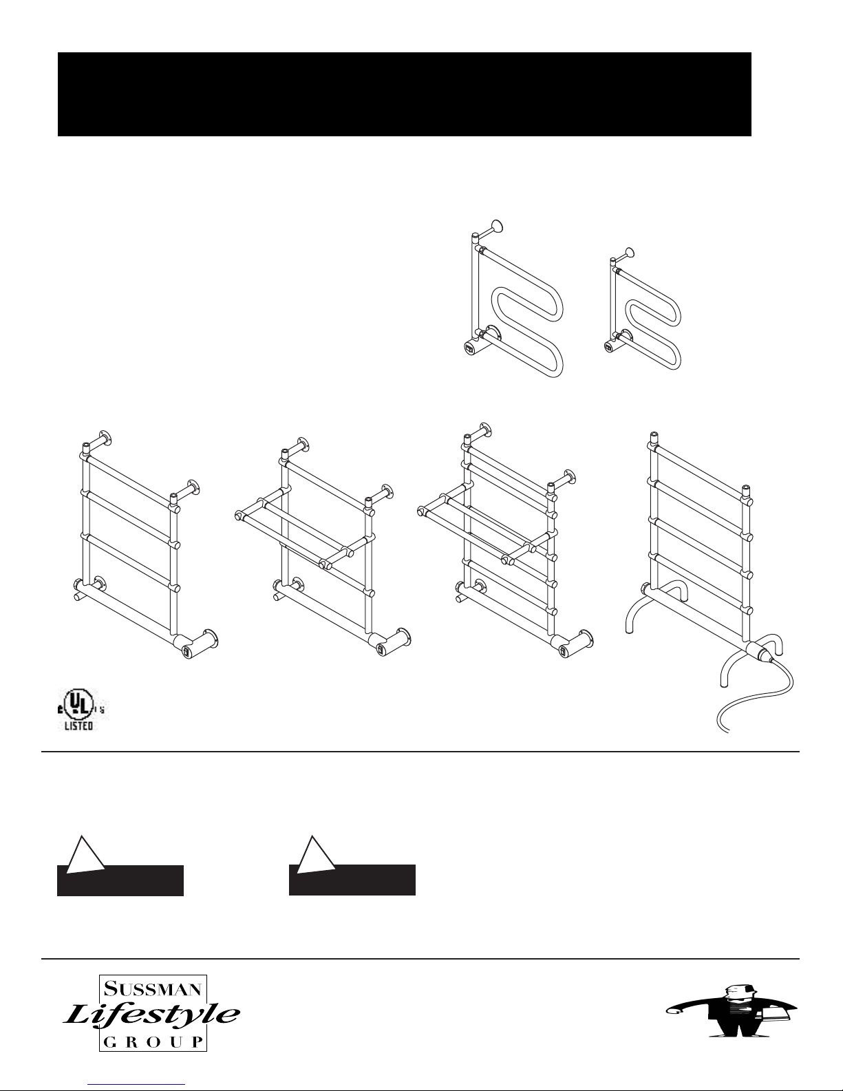
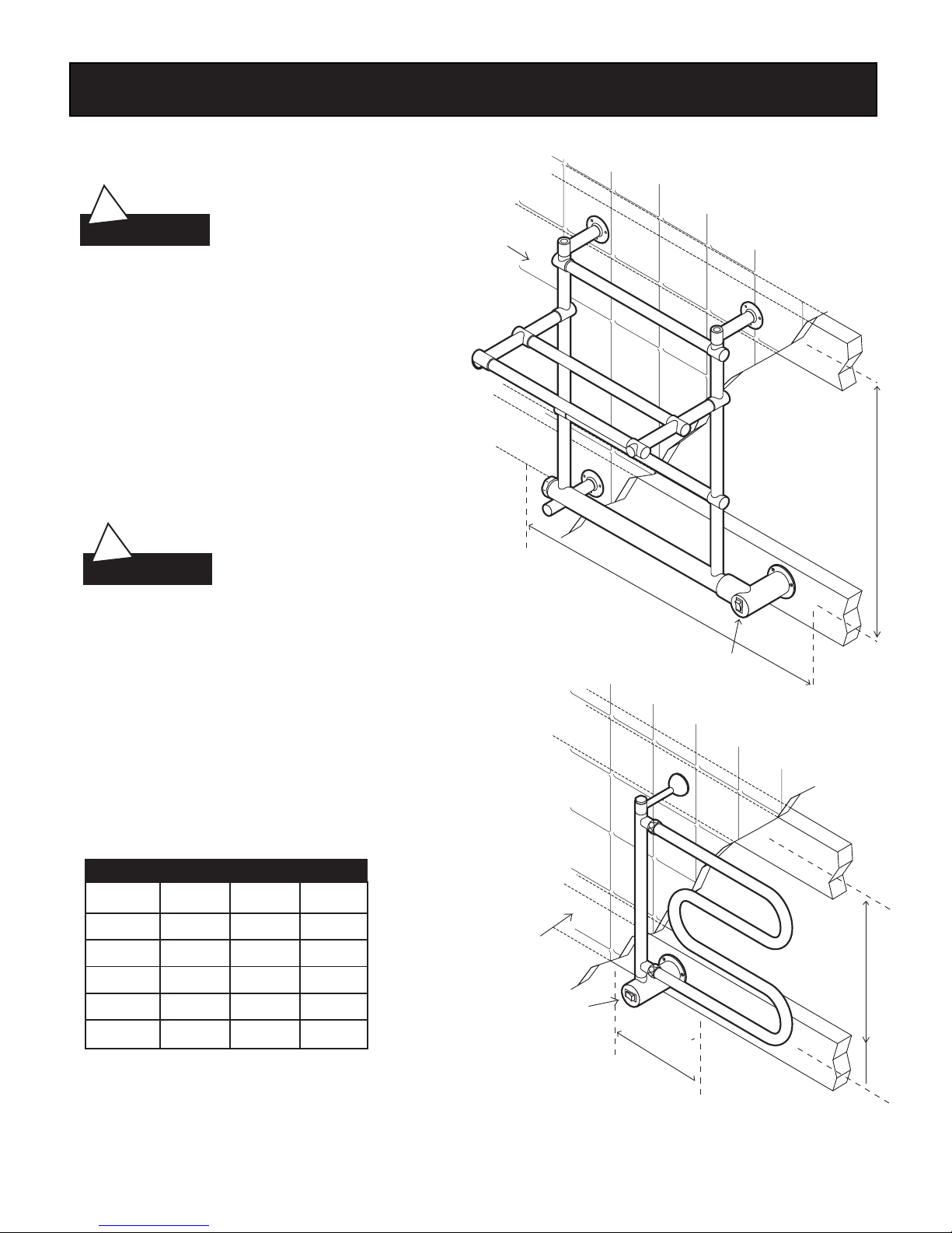
WARMATOWEL SPECIFICATIONS
____________________________________________________________ ___
Model No. Dimensions Amps Volts/Phase Weight (lbs.)
____________________________________________________________ __
W500 24 x 22.5 x 5 1.25 120/1 16
____________________________________________________________ __
W510 18 x 20.5 x 5 1.25 120/1 14
____________________________________________________________ __
W542 26 x 23 x 5 1.67 120/1 18
____________________________________________________________ __
W552 25.5 x 23 x 5* 1.67 120/1 28
____________________________________________________________ __
W554 21.5 x 23 x 5* 1.67 120/1 22
____________________________________________________________ __
W556 34 x 23 x 10 1.67 120/1 21
____________________________________________________________ __
*Add 10" for shelf width. All dimensions are in inches. ALL UNITS 120 VOLTS.
Inspect WarmaTowel
A. Unpack the Towel Warmer carefully to avoid any
damage or loss of any part. When opening the
box be sure that the parts are not accidentally
discarded. WarmaTowels are shipped in specially
designed shipping cartons. The entire surface of
the WarmaTowel is hand-wrapped to protect the
finish. It is your responsibility to immediately
inspect for any damage.
WARNING
!
WARNING
!
WARNING
!
Warma
Towel
Installation and Operating Instruction
®

Wall Preparation
2
Warma
Towel
Installation and Operating Instruction
®
• DO NOT mount the Warmatowel without
providing structurally secure headers as shown.
• DO NOT mount the towel warmer directly to
sheet rock or any other non-structural surface.
• Use longer fasteners as required if the finished
wall surface prevents adequate mounting with
the screws provided.
• Provide a clearance hole in the lower header
as required to route field wiring to the
WarmaTowel wiring box.
If a single gang electric box has been roughed-in,
contact the technical service dept. for a cover plate
and instructions. DO NOT install the WarmaTowel
without these instructions.
Cover plate part numbers & decorative finishes:
Polished Chrome 103854 PC
Polished Brass 103854 PB
Polished Nickel 103854 PN
Pewter 103854 P
Satin Nickel 103854 SN
Gold 103854 G
For Technical Service Assistance:
East Coast Tel: 1-800-767-8326
West Coast Tel: 1-800-727-8326
CAUTION
!
WARNING
!
®
MODEL X" Y"(min)Z(min)
W 500 16 5 2 x 4
W 510 22 1/2 5 2 x 4
W 542 24 22 2 x 6
W 554 20 1/4 22 2 x 6
W 552 23 7/8 22 2 x 6
HEADER DIMENSIONS
(inches)
Lower Header (Z)
Upper Header (Z)
Lower Header (Z)
Upper Header (Z)
Finished
wall surface
Finished
wall surface
Wiring Box
Wiring Box
Y
Y
X
X

Models W542, W552 & W554
BOX CONTENTS:
• Towel Warmer
• (12) screws
• (2) Upper threaded flanges
• (1) Lower Bracket
• (1) Lower bracket screw
• (1) Wiring flange
• (1) Small allen key
• (1) Large allen key
• Instruction & Operation Manual
• Warranty
1. Remove WarmaTowel and parts from the
packing materials
2. Rotate two upper brackets as shown
3. Spin on upper two threaded flanges as shown
4. Assemble lower bracket as shown
5. Using the smaller allen key provided, loosen
the wiring box set screw. DO NOT remove the
wiring box.
6. Rotate the wiring box as shown. Tighten the
set screw firmly to prevent the wiring box
from rotating.
NOTE: The wiring box and upper brackets on
model W542 can be rotated in either
direction to result in a right or left handed
wiring box.
7. Place the towel warmer in the desired
location. Use a level to insure proper
alignment. Mark the location of the wiring
box.
If a single gang electric box has
been roughed-in, see page 2
for instructions
3
Upper Brackets
Upper Threaded
Flanges
Wiring Box
Set Screws
Wiring
Box
Lower
Bracket
Level
Wiring
Box
WARNING
!
Warma
Towel
Installation and Operating Instruction
®

4
Wiring Box Set Screw(s)
Wiring Box
Wiring Flange
Wiring Box
Wiring Flange
BX Connector Lock Nut
BX Cable*
(or greenfield)
*Note: NM (non-metallic) cable, if permitted by National
and Local Codes may be used instead of BX cable
*Note: WarmaTowel wires are color coded:
BLACK for LINE, WHITE for NEUTRAL,
GREEN/YELLOW for EQUIPMENT GROUND.
11. Slide the wiring box onto the wiring flange
and tighten the set screw firmly. Secure the
upper threaded flanges and lower bracket
with screws provided.
9. Secure wiring flange to the wall with screws
provided. (Use longer screws as required by
construction conditions.)
WARNING
!
8. Assemble the BX cable
connector to the wiring
flange as shown.
Models W542, W552 & W554 (cont.)
TO PREVENT SHOCK HAZARD, BE CERTAIN THAT ELECTRICITY IS TUR NED OFF AT THE MAIN PANEL
BEFORE ANY WIRING IS DONE.
10. Connect wiring per instructions pg. 7.
WARNING
!
If a single gang electric box has been roughed-in, see page 2 for instructions
Warma
Towel
Installation and Operating Instruction
®

Models W500 & W510
TO PREVENT SHOCK HAZARD, BE CERTAIN THAT ELECTRICITY IS
TURNED OFF AT THE MAIN PANEL BEFORE ANY WIRING IS DONE.
BOX CONTENTS:
• Towel Warmer • (1) Small allen key
• (6) Screws • (1) Large allen key
• (1) Compression flange • Instruction & Operation Manual
• (1) Decorative cover • Waranty
• (1) Lower wiring flange
1. Place the compression flange on the upper support
bracket.
2. Using the smaller allen key provided, loosen the wiring
box set screw. DO NOT remove the wiring box.
3. Rotate the wiring box as shown. Tighten the set screw
firmly to prevent the wiring box from rotating.
4. Place the towel warmer in the desired location and
mark the location of the upper compression flange and
wiring box. Use a level to insure proper alignment.
*Note the WarmaTowel swing range.
5. Remove the compression flange from the upper support
bracket. Mount the compression flange to the wall with
the screws provided.
6. Slide the decorative cover onto the upper support
bracket as shown.
7. Insert the upper support bracket fully into the
compression flange.
8. T ighten the nut on the compression flange. Slide the
decorative cover over the compression flange.
9. Mount the lower wiring box per instructions on page 4.
NOTE: The compression flange nut can be rotated
to adjust flange center.
If a single gang electric box has
been roughed-in, then see page
2 for installation instructions.
5
Level
Upper Support Bracket
Compression Flange
Wiring Box
Compression
Flange Nut
Compression
Flange
Decorative
Cover
Upper
Support
Bracket
WARNING
!
WARNING
!
Warma
Towel
Installation and Operating Instruction
®

Models W556
BOX CONTENTS:
• Towel Warmer
with 7' grounding type power cord
• (2) tubu lar legs
• (2) leg screws
• (1) Large allen key
• Instruction & Operation Manual
• Warranty
1. With the unit unplugged, assemble the
tubular legs to the bottom of the towel
warmer as shown.
Note: Model W556 has no ON/OFF switch.
6
Tubular Legs
Leg Screws
Mounting Stud
Warma
Towel
Installation and Operating Instruction
®

7
Electric Towel Warmer
Thermal Fuse
Thermostat
Heating Element Wiring Box
Field Wiring
Electrical Specifications
Field Models: W500, W510, W542, W552. W554
Plug-in Model: W556
ELECTRICAL CONNECTIONS
TO PREVENT SHOCK HAZARD, BE CERTAIN THAT ELECTRICITY IS TUR NED OFF AT THE MAIN PANEL
BEFORE ANY WIRING IS DONE.
All wiring must conform to National Electrical and Local Cod es.
General: The WarmaTowel requires 120VAC, 60 Hz power supply. Specific amperage needed is listed in the WarmaTowel
Specifications Chart on page 1.
A. Electrical connections should be made as prescribed by th e National Electric and Local Codes, except for Model W556. The
unit should be field wired using 14 AWG min 90 ˚C-rated copper wire. All models are to be protected by a sep arate 15 amp
circuit breaker or equal.
B. Make connections between WarmaTowel and house wiring usin g approved connections to comply with National Electrical
Local Codes. LINE (black), NEUTRAL (white), and GROUND.
C. Install the WarmaTowel according to the specific instruct ions for each model.
TO PREVENT SHOCK HAZARD, NO BARE WIRE OR WIRE STRANDS SHOUL D
WARNING
!
WARNING
!
L
N
GRND
L
N
GRND
Switch
X
X
X
Warma
Towel
Installation and Operating Instruction
®

Optional Programmable Timer
Installation:
To The Installer
1. Read the operating instructions provided with the timer.
2. Disconnect power supply prior to installation to
prevent electrical shock.
3. Damage to the contacts caused by short circuiting will vo id
the warranty.
4. Wire in accordance with National Electrical and Local Cod e
requirements.
Be sure all connections are secure.
Double check all twist-on wire connectors.
6. Mount timer into wall box using supplied screws.
7. If timer does not operate, check that the timer's black w ire is connected to hot
line and not the load. If necessary, reverse connections to red and black wires
Manual Operation
The slide switch provides manual operation of the load, over riding the timer, Set to the "OFF" position,
the load will be continuously off, and if set to "ON", it wi ll be continuously on. For automatic timed
on's and off's, the switch must be in the "AUTO" position.
Programming
The timer dial contains 72 "trippers" which, when set at the inner perimeter of the dial, will turn the
switch "ON" at the time adjacent to the tripper. The switch will return to the "OFF" position when the
timer progresses past the inward trippers.
The 72 trippers allow multiple on/off sequences with a minim um on or off timer of 20 minutes.
To program, set all trippers inward for the duration of the on event.
For example, to turn unit on at 5:00 pm and off at 11:00 pm, leave inward the 18 trippers between
5 and 11 on the "pm" side of the dial. Make sure manual swit ch is in the "AUTO" position.
NOTE: For any times where "OFF" programming is desired, the trippers must be moved
to the outer perimeter of the dial.
Setting the Time
Rotate the dial clockwise until the correct time and "am" or "pm" is opposite the arrow on the plate.
CAUTION: Do not turn dial counter-clockwise, as the timer wi ll be damaged.
8
WarmaTowel
®
Installation and Operating Instruction
Wiring Diagram
LINE (black) LOAD (red)
NEUTRAL (white)
WarmaTowel
WARNING
!
This manual suits for next models
5
Table of contents
Popular Plumbing Product manuals by other brands

Medway
Medway Easy Toilet Riser quick guide

Pfister
Pfister NIA GT529-NI Quick installation guide

Roper Rhodes
Roper Rhodes HAM450B manual

Booth & Co
Booth & Co AXBRIDGE BC-AXB-206-CP user guide

Hans Grohe
Hans Grohe AXOR Starck Organic 12018 1 Series Installation/User Instructions/Warranty

HoMedics
HoMedics FAC-2 instruction manual