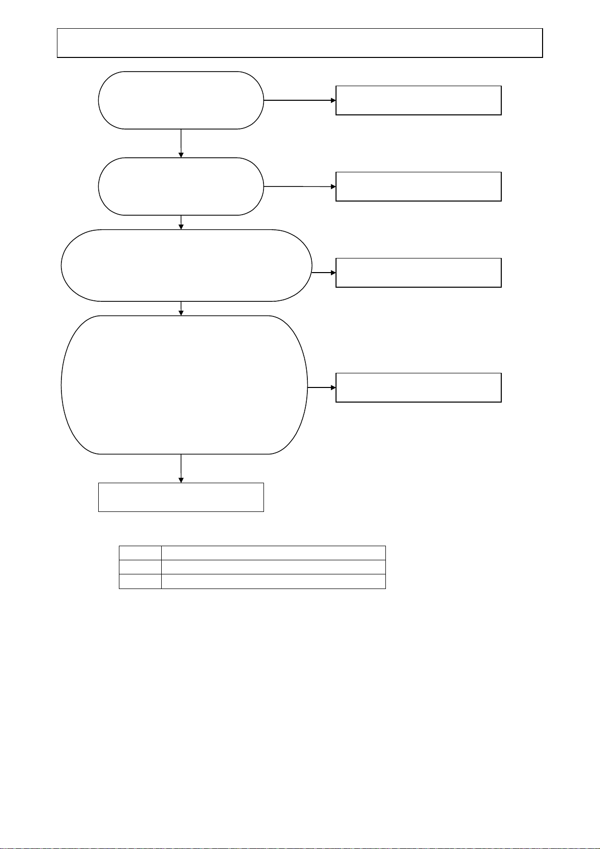
BEFORE MAINTENANCE AND INSPECTION (connected with the limit switch cables: red and black, brown)
Turn the breaker of your ship OFF. Remove FUSE 2.
Move the joint arm into the position between the upper limit switch and the lower limit
switch with the crank handle.
UPPER LIMIT SWITCH / LOWER LIMIT SWITCH (connected with the limit switch cables: yellow and
green) Check the current flows between the points, “NO”−”COM” with the tester.
The following cases show the normal conditions:
-A short is found when the lever of the limit switch is pressed.
-An open is found when the lever of the limit switch is released.
- The following voltages are detected, with the FUSE 2 removed and the breaker of your
ship ON.
※When the plus lead of the tester is connected to “COM” and the minus lead is connected to
“NO”, if 0V is detected with the limit switch ON and approx.7.3V with the limit switch OFF.
THE SENSOR LAMP FOR THE LIMIT SWITCH (connected with the limit switch cables: white and brown)
It is the ON/OFF switch of the sensor lamp for the monitor.
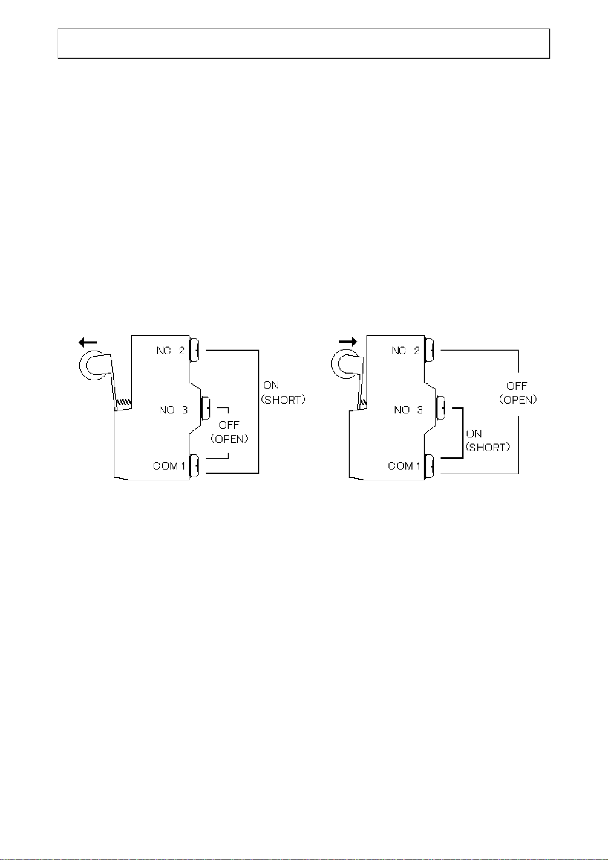
FIGURES OF LIMIT SWITCH CIRCUIT
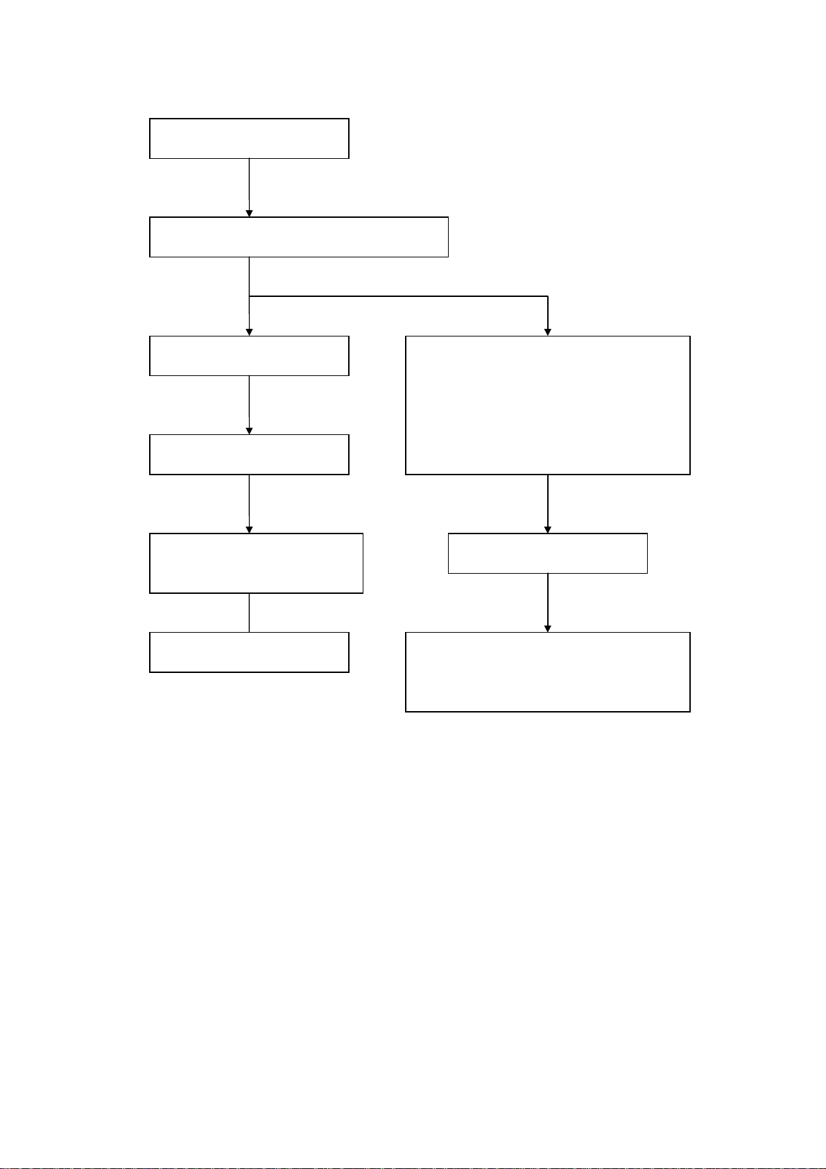
THE SYMPTOMS OF FAULTY LIMIT SWITCH
UPPER LIMIT SWITCH CAN NOT BE SET “ON”:
The hoist stops after going over the upper limit switch even if the power of the monitor is
OFF.
The fuse 2 will blow, because the hoist motor circuit keeps working even if the hoist is
stopped.
It damages the hoist motor circuit and hoist motor.
LOWER LIMIT SWITCH CAN NOT BE SET “ON”:
When turning the power of the monitor on, the hoist starts to be lowered and reaches the
lower damper rubber after going over the lower limit switch and then stops there.
The fuse 2 will blow, because the hoist motor circuit keeps working even if the hoist is
stopped.
It damages the hoist motor circuit and hoist motor.
Some dust or dirt attached on the limit switch might be the cause of malfunction.
When the hoist is on the lower position than the upper limit switch, it is always raised after putting
FUSE 2 back and turning the breaker of your ship ON. If the hoist stops on the halfway, another
cause is suspected.
-9-
HOW TO CHECK THE LIMIT SWITCH
THE SYMPTOMS OF FAULTY LIMIT SWITCH