Suzuki RM85/LK5 User guide

K5
July ’04 Printed in Japan (TK) 02
99505-01095-01E
FOREWORD
This motorcycle has been designed and produced utilizing Suzuki’s most modern
technology. The finest product, however, cannot perform properly unless it is cor-
rectly assembled and serviced. This set-up manual has been produced to aid you in
properly assembling and servicing this motorcycle.
Please review this set-up manual carefully before performing any work. Take special
care to properly perform the required assembly and servicing marked by either a
Warning or a Caution. Failure to follow the directions in either of these two (2) cate-
gories could lead to serious problems. #and areas are
denoted to emphasize certain areas and carry the following meanings:
#
Indicates a potential hazard that could result in death or injury.
Indicates a potential hazard that could result in motorcycle damage.
This set-up manual is based on a motorcycle of standard specification. Some minor
differences from this manual may be found in other specifications.

1
LOCATION OF PARTS
Carefully remove the various component parts packaged around the motorcycle.
Check off each of the components as shown in the photograph.
Two complete sets are required for units packed two par crate.
1. Remove the carton, then remove the bolts of the motorcycle holding bracket.
2. Remove the bolt, washer, plate and nut of the front wheel.
3. Remove the bolts from the crate, then lift the steel frame to separate it from the base of the crate.
Check all the components which have been removed from the base of the crate.
Keep the position of front brake master cylinder with their caps facing upward until they are installed.
1 3
2
AA
CC
DD
EE
FFGG
HH
M
II
BB
JJ
KK
LN
O
P
L
M
N
O
P
RR
QQ

2
Parts listed above are installed respectively into the positions as follows.
Item Part Name Q’ty Remarks
A
Number plate 1
Flange bolt 1 6 × 20 mm
Washer 1 OD:14.0 ID:6.5
B Radiator louver 1
C
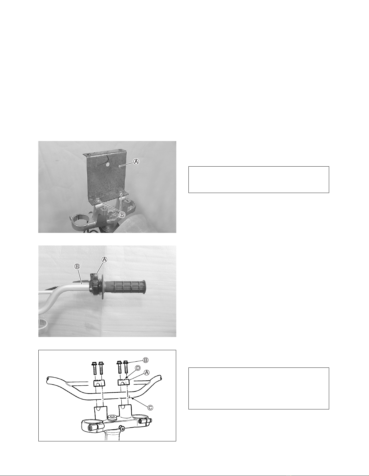
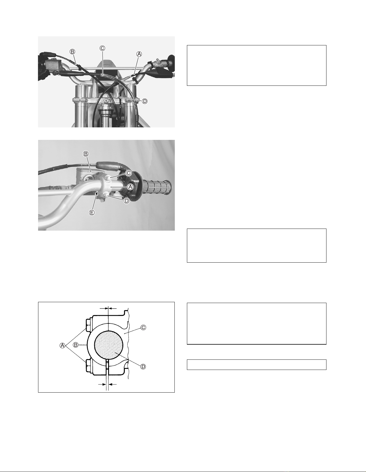
Handlebars assembly 1
Clamp 2
Flange bolt 4 8 × 35 mm
Clutch lever cover 1
Fuel tank vent hose 1
Screw 1 5 × 16 mm
For throttle assembly
Clamp 1 For throttle cable
Strap 2 L:120
Engine stop switch holder 2 Upper and lower
Screw (with lock washer) 1 3 × 14 mm
D
Radiator cover 1
Flange bolt 3 6 × 12 mm
Stepped washer 3 OD:16.0 ID:6.5 T:3.5
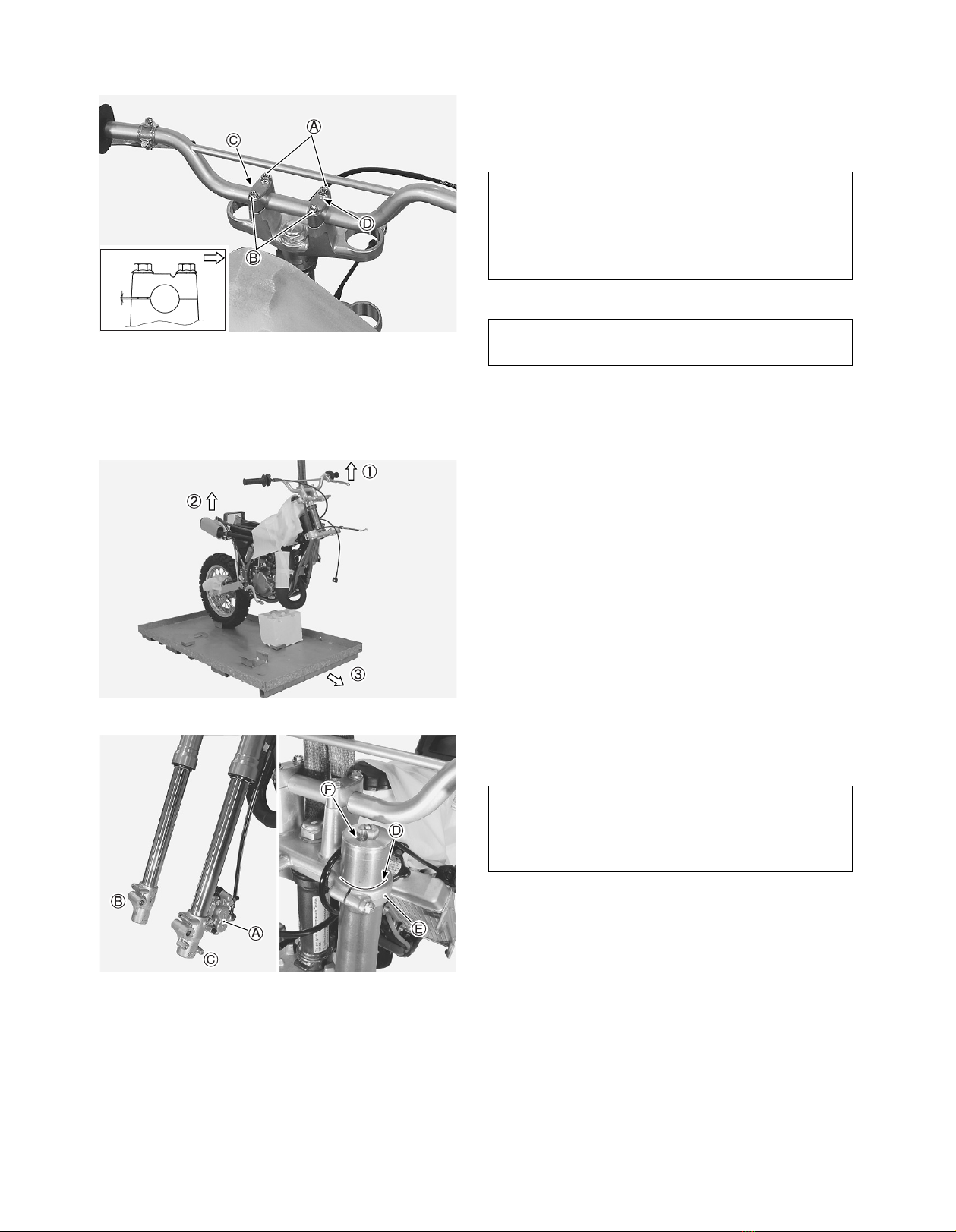
EFront fork assembly 2 Right and Left
Flange bolt 6 8 × 40 mm
F
Seat assembly 1
Flange bolt 2 6 × 16 mm
Washer 2 OD:20.0 ID:6.5 T:1.6
G
Rear fender 1
Washer 2 OD:26.0 ID:6.5
Flange bolt 3 6 × 30 mm
Washer 4 OD:20.0 ID:6.5 T:1.2
Self-lock nut 2 6 mm
Flange bolt 1 6 × 20 mm
Washer 2 OD:18.0 ID:6.5 T:1.6
Flange self-lock nut 2 6 mm (Black)
Item Part Name Q’ty Remarks
H
Front fender 1
Flange bolt 4 6 × 20 mm
Stepped washer 4 OD:16.0 ID:6.5 T:3.5
Stepped washer 4 OD:17.0 ID:6.5 T:7.0
I
Front axle 1
Front wheel spacer 2
Washer 1 OD:20.0 ID:12.5
Axle nut 1 12 mm
Cotter pin 1 L:27.0
JFront brake hose clip 2 Inner and Outer
Flange bolt 2 6 × 16 mm
KFront brake hose guide 1
Flange bolt 1 6 × 20 mm
LFront fork protector 2 Right and Left
Flange bolt 6 6 × 10 mm
M Front wheel assembly 1
NFrame cover 2 Right and Left
Strap 2 L:140
OStand 1
P
Main jet 3 Exchanging parts
Spark plug and spoke
nipple wrench 1
Q Owner’s manual 1
R Fuel label 1 For limited market
OD : Outside diameter (mm)
ID : Inside diameter (mm)
L : Length (mm)
T : Thickness (mm)
TL
OD ID
NOTE:
The parts shown as Item R in the above table are supplied for limited markets.
N
EL
I
A C
ID
RFGKEHL
BJMO
N

3
The photograph shown indicate the parts dismounted
from the motorcycle in addition to the items shown in
the preceding page.
A: Throttle assembly
Engine stop switch assembly
Clutch cable
SPARE PARTS
Item Part Name Q’ty
1Cylinder head O-ring No.1 2
2Cylinder head O-ring No.2 2
3Exhaust pipe O-ring 2
4Cylinder cover gasket No.1 2
5Cylinder cover gasket No.2 1
6Cylinder gasket 2
7Crankcase gasket 1
8Clutch cover gasket 1
9Piston complete 1
0Piston ring 2
APiston pin bearing 1
BPiston pin 1
CPiston pin circlip 2
DExhaust valve rod bush 2
EBrake lever 1
FClutch lever 1

4
Before assembling the motorcycle, thoroughly
understand the “Safety Check Out” described on
page 27.
After completion of assembly, carefully check the
motorcycle referring to the “Safety Check Out”,
then deliver the motorcycle to the customer.
ASSEMBLY
REMOVING THE BRACKET
Remove the bracket from the handlebar mounting
position.
A: Bracket
B: Bolt
HANDLEBARS
Loosen the throttle housing retaining screws.
Insert the throttle assembly onto the handlebars.
A: Throttle assembly
B: Handlebars
Install the handlebars assembly using the two clamps
and the four bolts.
A: Clamp
B: 8 × 35 mm flange bolt
C: Dot mark
D: Punch mark
NOTE:
The bracket and bolts are no longer needed
and these may be discarded.
NOTE:
The punch mark on the clamps shows front
side.
Align the dot mark on the handlebars with the
mating surface of the front side of left clamp.

5
Tighten the handlebar clamp bolts to the specified
torque.
"
""
"Handlebar clamp bolt: 26 N·m (2.6 kgf-m)
A: 8 × 35 mm flange bolt
B: 8 × 35 mm flange bolt
C: Dot mark
D: Punch mark
1. Lift the front of motorcycle by using a hoist.
2. Raise the rear of motorcycle.
3. Pull the crate base forward, then balance the
motorcycle.
FRONT FORK
Insert each fork leg assembly into the lower and upper
brackets.
Adjust the line of front fork to the top face of the upper
bracket and air valve is positioned at the front.
A: Caliper
B: Right fork leg
C: Left fork leg
D: Line
E: Front fork upper bracket
F: Air pressure
NOTE:
To install the handlebars correctly, first tighten
the bolt A
AA
Aof the front side with specified
torque and then tighten the bolt B
BB
Bof the rear
side.
Make sure that the clamp has no clearance at
the front side as shown in the illustration.
FRONT
Keep the position of front brake master cylinder
with its cap facing upwards until it is installed.
Install the front fork assembly with front brake
caliper to the left side.

6
FRONT FORK (RM85L)
Insert each fork leg assembly into the lower and upper
brackets.
Adjust the line of front fork to the top face of the upper
bracket and air valve is positioned at the front.
A: Caliper
B: Right fork leg
C: Left fork leg
D: Line
E: Front fork upper bracket
F: Air pressure
Tighten the lower bracket side bolts to the specified
torque.
"
""
"
Front fork lower bracket bolt: 23 N·m (2.3 kgf-m)
A: Front fork assembly
B: 8 × 40 mm flange bolt
Tighten the upper bracket side bolts to the specified
torque.
"
""
"Front fork upper bracket bolt: 23 N·m (2.3 kgf-m)
A: Front fork assembly
B: 8 × 40 mm flange bolt
Keep the position of front brake master cylinder
with its cap facing upwards until it is installed.
Install the front fork assembly with front brake
caliper to the left side.

7
#
A: Clutch cable
B: Throttle cable
C: Front brake hose
D: Engine stop switch wiring harness
FRONT BRAKE MASTER CYLINDER
Remove the bolts and holder from the front brake mas-
ter cylinder.
Install the front brake master cylinder onto the handle-
bars.
Align the dot mark on the handlebars with the master
cylinder-to-holder fitting surface.
Tighten the master cylinder mounting bolts to the
specified torque.
"
""
"Front brake master cylinder mounting bolt:
10 N·m (1.0 kgf-m)
A: Holder
B: Front brake master cylinder
C: Flange bolt
D: Flange bolt
E: Dot mark
A: Bolt
B: Holder
C: Front brake master cylinder
D: Handlebars
The line drawings on page 25 and 26 show the
proper routing of the control cables, hose and
wirings.
Refer to them in addition to following the
instructions carefully.
NOTE:
To install the holder correctly, first tighten the
bolt C
CC
Cof the upper side with specified torque
and then tighten the bolt D
DD
Dof the lower side.
NOTE:
Install the holder in position according to the
mark “UP”.
Make sure that the holder has no clearance at
the upper side as shown.
Check for brake fluid leakage.

8
FRONT FENDER
Install the front fender with four sets of mounting parts
as shown.
Each of the four mounting bolts requires two stepped
washers.
A: Front fender
B: Stepped washer OD:17.0 mm ID:6.5 mm T:7.0 mm
C: Stepped washer OD:16.0 mm ID:6.5 mm T:3.5 mm
D: 6 × 20 mm flange bolt
Install the front fender to the front fork lower bracket.
A: 6 × 20 mm flange bolt
B: Stepped washer OD:16.0 mm ID:6.5 mm T:3.5 mm
C: Front fork lower bracket
FRONT REAR
BRAKE DISC
To prevent brake squeaking and pad contamination,
carefully clean the front and rear brake disc plates with
alcohol or other non-petroleum based solvent.
This will remove the rust-preventive coating and dirt.
Mount the front wheel assembly properly.
A: Right fork leg
B: Left fork leg
C: Cotter pin L:27.0 mm
D: Axle nut
E: Washer OD:20.0 mm ID:12.5 mm
F: Spacer
G: Front axle

9
Carefully insert the front brake disc plate between the
caliper brake pads.
A: Pads
B: Disc plate
LEFT RIGHT
Attach the spacers to the front wheel hub as shown in
the photographs.
A: Front wheel spacer
LEFT RIGHT
Insert the front axle from the left side of the fork legs.
Place the washer on the right end of the front axle.
A: Front axle
B: Washer OD:20.0 mm ID:12.5 mm
Tighten the front axle nut to the specified torque.
"
""
"Front axle nut: 44 N·m (4.4 kgf-m)
#
A: Axle nut 12 mm
B: Cotter pin L:27.0 mm
NOTE:
The large flange side of the spacer faces the
hub.
Never use force to install the front axle.
If it cannot be installed by hand, it is not cor-
rectly aligned.
Insert the cotter pin through the axle shaft and
bend the ends properly.

10
STAND
Insert the boss of stand to the hole of frame as shown
in the photograph.
A: Stand
Place the motorcycle on the stand, then remove the
hoist hook.
LEFT RIGHT
FRONT FORK PROTECTOR
Install the front fork protector to the front fork.
A: Front fork protector
B: 6 × 10 mm flange bolt
C: Left fork leg
D: Right fork leg
BRAKE HOSE CLIP
Align the groove of front brake hose with the groove of
brake hose clip.
Install the brake hose clip to the front fork protector.
A: Brake hose clip (Inner)
B: Front brake hose
C: Groove
D: Brake hose clip (Outer)
E: Front fork protector
F: 6 × 16 mm flange bolt

11
FRONT BRAKE HOSE GUIDE
Pass the front brake hose through the guide.
Install the guide to the front fork lower bracket.
A: Front brake hose guide
B: Front brake hose
C: 6 × 20 mm flange bolt
D: Front fork lower bracket
THROTTLE
Install the throttle assembly at correct position.
Tighten the throttle assembly with two screws after
assembly is positioned so that there is approximately
0.5–1.0 mm clearance of between the inner position of
the grip and the end of the handlebars.
#
A: Throttle assembly
B: 5 × 16 mm screw
CLUTCH CABLE
Pass the clutch cable through the lever cover.
A: Clutch cable
B: Clutch lever cover
Check to ensure that the throttle operates freely
and closes automatically.

12
Turn the clutch cable adjuster and lock nut in as far as
possible and align the slots.
Insert the inner cable end into the recess in the clutch
lever, then pull on the outer cable housing and insert it
into the adjuster.
Do not adjust at this time.
Adjustment will be covered in the SERVICING section.
Install the lever cover.
A: Clutch cable
B: Adjuster
C: Lock nut
D: Cable end
E: Clutch lever cover
ENGINE STOP SWITCH
Hook the holders on the grooves of the engine stop
switch assembly.
A: Engine stop switch assembly
B: Holder (Upper)
C: Holder (Lower)
D: Thread cutting
Install the engine stop switch to the left of handlebars.
A: Engine stop switch assembly
B: 3 × 14 mm screw (with lock washer)
NOTE:
Before installing the cable, grease the cable
end.
NOTE:
Use the holder with an internal thread cutting at
the lower side.

13
CLAMP
Clamp the engine stop switch wiring harness with har-
ness straps.
A: Strap L:120 mm
B: Engine stop switch wiring harness
Clamp the throttle cable to the handlebar bridge pipe.
A: Throttle cable
B: Clamp
C: Handlebars
FRONT NUMBER PLATE
Insert the hole of front number plate to the boss of
front fork lower bracket.
Align the recess of front number plate on the front fork
upper bracket.
A: Front number plate
B: Hole
C: Boss
D: Slit
E: Recess
NOTE:
The larger diameter side of the cable clamp
should be connected to the handlebars.

14
Install the front number plate with flange bolt.
Pass the strap of the number plate around the handle-
bar bridge pipe and through the guide.
#
A: Front number plate
B: 6 × 20 mm flange bolt, washer OD:14.0 mm ID:6.5 mm
C: Strap
D: Front brake hose
E: Throttle cable
F: Clutch cable
G: Handlebar bridge pipe
H: Guide
REAR FENDER
Remove the bracket from the frame.
A: Bracket
B: Bolt
C: Nut
Insert the hole of rear fender into the boss of frame.
Install the rear fender to the frame.
Temporarily tighten with fitting parts as shown in the
photograph.
A: Boss
B: Hole
C: Rear fender
D: Flange bolt 6 × 30 mm
E: Washer OD:26.0 mm ID:6.5 mm
F: 6 mm flange self-lock nut (Black)
G: Washer OD:20.0 mm ID:6.5 mm T:1.2 mm
H: Frame
Route the brake hose in front of the number
plate.
Route the throttle cable and clutch cable below
the number plate mounting boss.
NOTE:
The bracket, bolt and nut are no longer needed
and may be discarded.

15
LEFT RIGHT
Install the rear fender with fitting parts as shown in the
photograph.
Securely tighten the two nuts Ifixed temporarily.
A: Rear fender
B: 6 × 20 mm flange bolt
C: 6 × 30 mm flange bolt
D: Washer OD:20.0 mm ID:6.5 mm T:1.2 mm
E: 6 mm self-lock nut
F: Frame
G: Spacer
H: Second muffler
I: 6 mm flange self-lock nut (Black)
J: Rubber cushion
K: Washer OD:18.0 mm ID:6.5 mm
LEFT RIGHT
FRAME COVER (RIGHT AND LEFT)
Remove the frame cover mounting bolts and stepped
washers attached on the frame.
A: 6 × 45 mm flange bolt
B: Stepped washer OD:18.0 mm ID:6.5 mm T:3.5 mm
Insert the hole of frame cover to the boss of frame.
Install the frame cover to the frame with the fitting
parts.
A: Frame cover
B: 6 × 45 mm flange bolt
C: Stepped washer OD:18.0 mm ID:6.5 mm T:3.5 mm
D: Boss
E: Strap L:140 mm
F: Frame
SEAT
Fit the screw on the fuel tank in the groove on the front
of the seat and insert the seat boss into the guide on
the frame and push it forward.
Then fix the seat assembly together with rear part of
the frame cover.
A: Groove
B: Screw
C: Boss
D: Guide
E: 6 × 16 mm flange bolt
F: Washer OD:20.0 mm ID:6.5 mm T:1.6 mm
G: Frame cover
H: Seat assembly
I: Frame

16
RADIATOR LOUVER
Insert the boss of radiator louver into the hole of radia-
tor.
Install the radiator louver as shown in the photograph.
A: Radiator louver
B: Boss
C: Hole
RADIATOR COVER
Install the radiator cover with flange bolt and stepped
washer.
A: Radiator cover
B: 6 × 12 mm flange bolt
C: Stepped washer OD:16.0 mm ID:6.5 mm T:3.5 mm
FUEL TANK VENT HOSE
Install the fuel tank vent hose to the fuel tank cap.
Insert the free end of fuel tank vent hose to the hole of
front number plate.
A: Fuel tank vent hose
B: Fuel tank cap
C: Front number plate
D: Hole
FUEL LABEL (FOR LIMITED MARKET)
Stick the label on the fuel tank.
A: Fuel tank
B:Fuel label
Be sure not to bend or twist the hose when
installing.
UNLEADED
FUEL ONLY

17
SERVICING
FRONT REAR
BRAKE FLUID
Keep the motorcycle upright and place the handlebars
straight.
Check the brake fluid level in both the front and rear
master cylinder reservoirs.
If the fluid level is below the lower level indicated in the
figure, add the correct type of brake fluid.
Refer to the chart below for the proper selection.
A: Lower level line
B: Upper level line
FRONT
BRAKE AIR BLEEDING
Any air which may have been trapped in the brake fluid
circuit must be bled completely.
If the brake lever or brake pedal feels spongy or weak,
then most likely there is air in the hydraulic circuit.
To bleed the air from the front brake, use the following
procedure:
1. Connect a clear hose to the air bleeder valve and
run the hose into a suitable clear container.
2. Pour approximately 1/2 in of brake fluid into the con-
tainer so that the end of the clear hose is sub-
merged and cannot draw any additional air back into
the circuit during the air bleeding servicing.
3. Close the valve, pump and squeeze the lever, and
open the valve while squeezing brake lever.
4. Repeat this process until the fluid flowing into the
receptacle no longer contains air bubbles.
5. After bleeding the brake circuit, tighten the bleeder
valve to the specified torque.
Reinstall the rubber protective cap.
6. Be sure to check the brake fluid level in the reservoir
tank.
"
""
"Brake caliper air bleeder valve:
7.5 N·m (0.75 kgf-m)
A: Bleeder valve
Specification and Classification
DOT 4
Be careful not to spill any brake fluid on the
paint or plastic components as they will be
damaged.
NOTE:
Do not drop brake fluid level below lower level
line while bleeding air.

18
REAR
The procedure to bleed the rear brake is identical to
that of the front.
A: Bleeder valve
FRONT BRAKE LEVER
Check the brake lever play.
Front brake lever play: 5–20 mm
If adjustment is necessary, carry out the procedure
below:
1. Loosen the lock nut A.
2. Turn the adjuster Bin or out until the correct play.
3. Tighten the lock nut A.
THROTTLE CABLE
Check the throttle cable play at the throttle grip A.
Throttle cable play: 2.0–4.0 mm
If adjustment is necessary, carry out the procedure
below:
1. Loosen the throttle cable adjuster lock nut B.
2. Turn the adjuster Cin or out until the correct play.
3. Tighten the lock nut Bwhile holding the adjuster.
4. Place the rubber boot D.
#
After the adjustment is completed, check that
handlebar movement does not raise the engine
idle speed and that the throttle grip returns
smoothly and automatically.

19
CLUTCH CABLE
Check the clutch lever play at the clutch lever end
when the lever is lightly pulled in towards the grip.
Clutch lever play: 10–15 mm
If adjustment is necessary, carry out the procedure
below.
1. Loosen the lock nut Eof the clutch lever adjuster.
Turn in the adjuster Das far as possible.
2. Loosen the cable adjuster lock nut A.
Turn the cable adjuster Bto obtain the correct play.
3. Tighten the lock nuts Aand place the rubber boot
C.
Minor adjustments can now be made with the clutch
lever adjuster D.
4. Tighten the lock nut Eand place the lever cover F.
REAR BRAKE PEDAL
Check the rear brake pedal height.
Brake pedal height: 0–10 mm
If the rear brake pedal height is not correct, adjust in
the following manner:
1. Loosen the lock nut A.
2. Rotate the push rod Bto locate the pedal to the
correct height below the top face of the footrest C.
Be sure to measure this height carefully.
3. Tighten the lock nut Ato the specified torque.
"
""
"Rear brake push rod lock nut A
AA
A:
18 N·m (1.8 kgf-m)
DRIVE CHAIN
Check the drive chain slack.
Drive chain slack: 40–50 mm
If it is too tight or too loose, follow these procedures:
1. Loosen the axle nut.
2. Loosen the lock nut.
3. Adjust the slack in the drive chain by turning the
right and left chain adjuster bolts.
4. Proper chain slack is obtained when the drive chain
slack is up and down slack in the chain, at a point
midway between the two sprockets.
A: Axle nut
B: Lock nut
C: Adjuster bolt
D: Reference marks
Table of contents
Other Suzuki Motorcycle manuals

Suzuki
Suzuki GS1000 User manual

Suzuki
Suzuki 2013 C90T Boulevard User manual

Suzuki
Suzuki FA50 User manual

Suzuki
Suzuki DR650SE User manual

Suzuki
Suzuki Intruder VS1400 User manual

Suzuki
Suzuki RM85 Application guide

Suzuki
Suzuki RGV250L 1990 User manual

Suzuki
Suzuki FZ50 User manual

Suzuki
Suzuki SFV650 User manual

Suzuki
Suzuki GS1100E User manual

Suzuki
Suzuki GS1100L 1980 User manual

Suzuki
Suzuki GN125F User manual

Suzuki
Suzuki RM250 Application guide

Suzuki
Suzuki FL125S User manual

Suzuki
Suzuki DR600S User manual

Suzuki
Suzuki RM-Z250 Application guide

Suzuki
Suzuki DR 125 User manual

Suzuki
Suzuki Intruder VL1500B User manual

Suzuki
Suzuki RM-Z450 Application guide

Suzuki
Suzuki GSX-1300R User manual