3
10277L
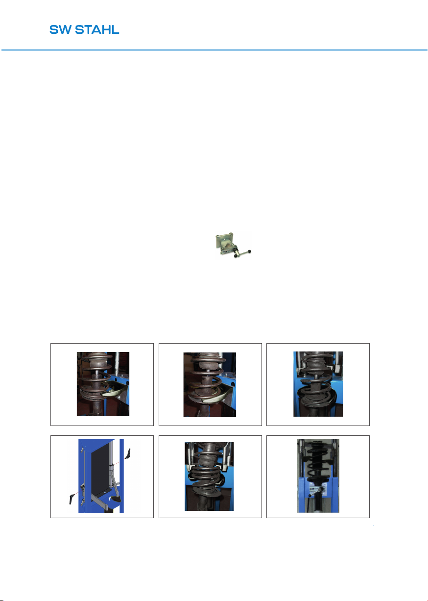
1. BESCHREIBUNG
Das Stoßdämpfer-Ein-/Ausbaugerät, Modell 10277L,
besteht aus einer pulverbeschichteten Metallrohrstruktur.
Auf dieser Struktur befindet sich ein fest mit dem
Aufbau verbundener Pneumatikzylinder, der durch
Druckluft aus- und eingefahren wird und dabei die
Feder des von Spannbacken gehaltenen Stoßdämpfers
zusammendrückt oder entspannt.
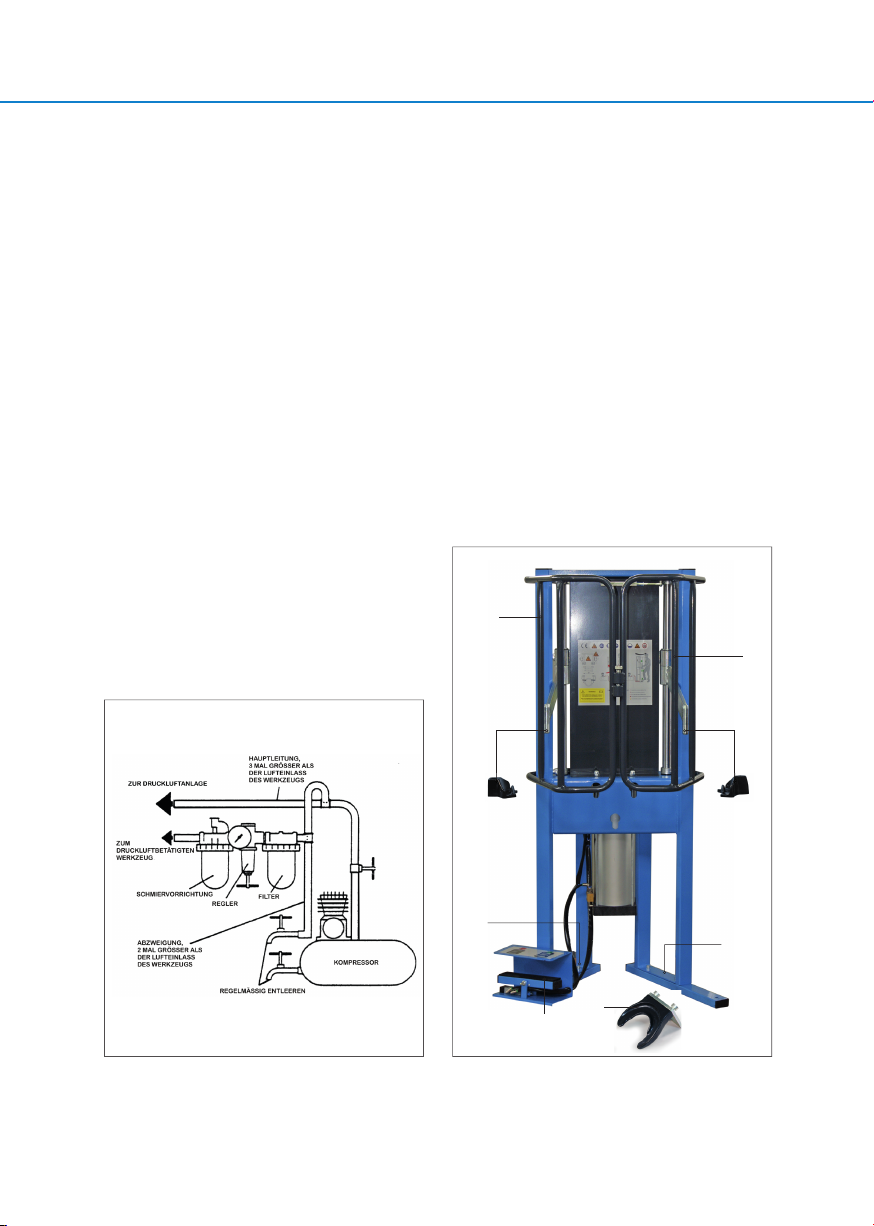
2. ZULÄSSIGER GEBRAUCH
Die Maschine 10277L ist eine druckluftbetätigte Vorrichtung, die
für den Ein-/Ausbau von Autostoßdämpfern bestimmt ist.
Jeder davon abweichende Gebrauch ist als missbräuchlich und
gefährlich anzusehen. Der Hersteller ist nicht haftbar für
bestimmungsfremden Gebrauch.
3. TECHNISCHE DATEN
Betriebsdruck
Min 6 bar, Max 10 bar
Presskraft
735 Kg (6 atm)
1.226 Kg (10 atm)
Druckhub des Zylinders
330 mm
Abmessungen
520x300x1400 mm
Maschinengewicht
68 Kg
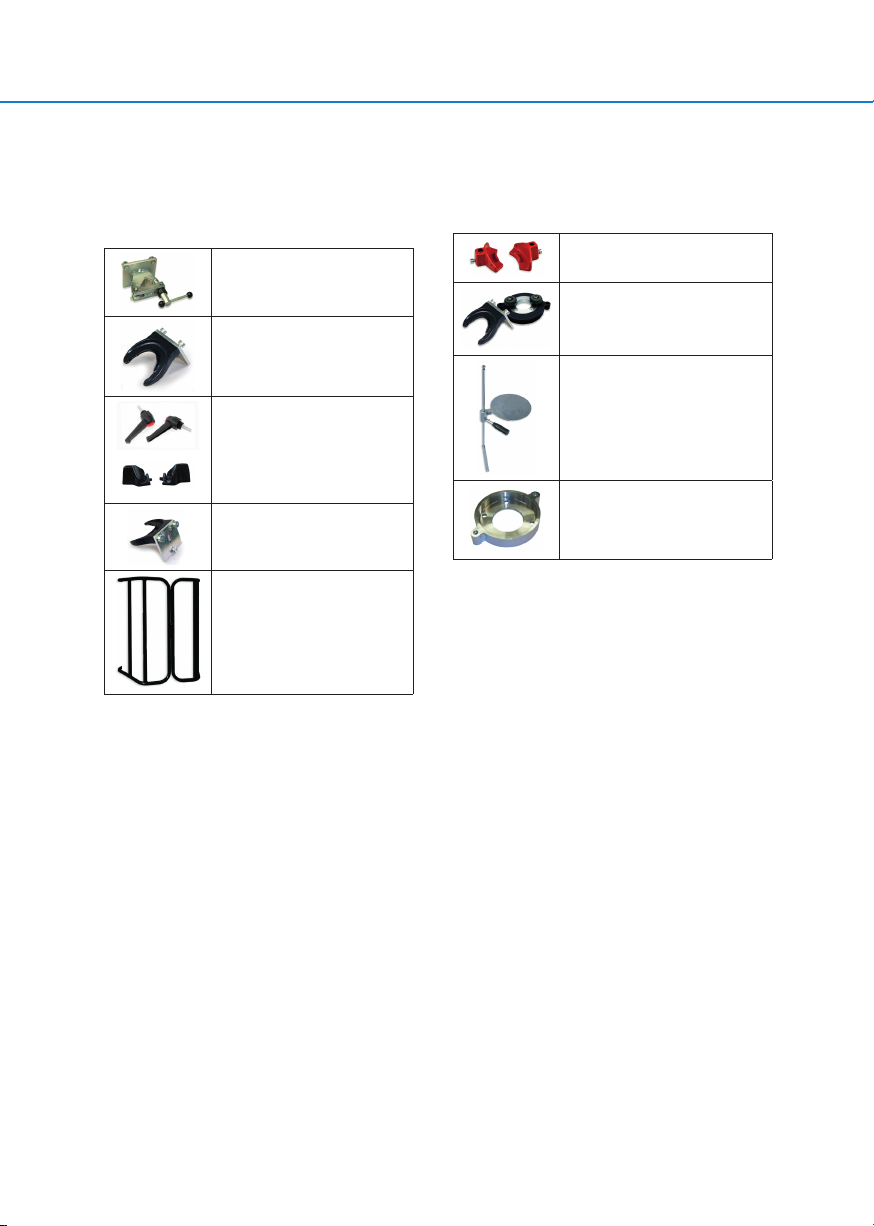
Kleine Federaufnahme
Ø78÷130 mm
(Gewicht 3,6 Kg)
Große Federaufnahme
Ø125÷205 mm
(Gewicht 4,2 Kg)
Schraubstock
Gewicht 3,7 Kg
4. SICHERHEITSHINWEISE
Das Stoßdämpfer-Ein-/Ausbaugerät, Modell
10277L, erfordert besondere Vorsicht beim Gebrauch, da die
zusammengepressten Stoßdämpfer eine potentielle
Gefahrenquelle darstellen. Die Gefahr ist durch die Kraft der
Federspannung gegeben.
Das Gerät darf nur mit richtig montiertem Schutzkäfig
eingesetzt werden.
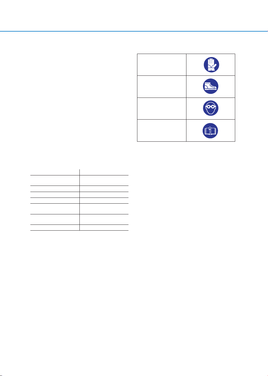
4.1.1 Individuelle Schutzmittel
Im Folgenden werden die individuellen Mindestschutzmittel
aufgeführt, die für die Anwendung unseres Gerätes
erforderlich sind.
Schutzhandschuhe
Schutzschuhwerk
Schutzbrille
Betriebshandbuch
4.1.2 Gefahrensymbole
Die Maschine ist mit Piktogrammen versehen, die
auf die vorhandenen Restgefährdungen und auf die
beim Maschinengebrauch zu tragenden individuellen
Schutzmittel hinweisen.
Die Piktogramme sind wesentlicher Maschinenbestandteil. Die
Schilder müssen bei Verlust, Beschädigung oder wenn
sie unleserlich sind, sofort durch neue ersetzt und an
derselben Stelle angebracht werden. Die neuen
Piktogramme können beim Hersteller angefordert werden.
5. TRANSPORT - HANDLING
Das Gewicht der verpackten Maschine 10277L beträgt Kg. 68
(ohne Federaufnahmen). Es muss ein für das Gewicht
auslegtes Transportmittel benutzt werden.
Den Karton mit der Maschine auf dem Gabelstapler mit
Gurten befestigen, um die Stabilität zu erhöhen.
Alle nötigen Vorsichtsmaßnahmen anwenden, damit
der Karton mit Abmessungen 650x400x1400 mm nicht
umkippen oder herunterfallen kann und dadurch das
Personal beim Handling oder Drittpersonen in der Nähe
gefährdet.
6. AUSPACKEN
Die Verpackung besteht aus einem Pappkarton mit den
Abmessungen 650x400x1400 mm. Der Karton ist mit
Metallklammern geschlossen.
Pfeile zeigen die Richtungen an, in denen der Karton
gehandhabt werden muss (der Nach-Oben-Pfeil gibt die
Oberseite des Kartons an).