Swagelok M200 Installation instructions

M200 Calibration Unit
User Instructions

2
Contents
M200 Calibration Unit User Instructions . . . . . . . . . . . . . . . . . . . . . . . . . . . . . . . . . . 3
Unité d’étalonnage pour alimentation M200 Instructions d’utilisation . . . . . . . . . . . . . . . . . . . 9
M200 Kalibrierungsgerät Bedienungsanleitung . . . . . . . . . . . . . . . . . . . . . . . . . . . . . . 15
Unidad de calibración M200 Instrucciones para el usuario . . . . . . . . . . . . . . . . . . . . . . . . 21
Калибровочное устройство M200 Инструкция пользователя . . . . . . . . . . . . . . . . . . . . . . . .27
M200 校正ユニット ユーザー・マニュアル . . . . . . . . . . . . . . . . . . . . . . . . . . . . . . . . . .33
M200 보정 장치 사용 설명서 . . . . . . . . . . . . . . . . . . . . . . . . . . . . . . . . . . . . . . . 39
M200 45

3
M200 Calibration Unit
User Instructions
Included with Calibration Unit
Welding cables Wire harness (Input/Output) Dual Banana Jacks
SWS-M200-CAL
SWS-M200-CAL-WELD-CABLE SWS-M200-CAL-SENS-WR
M100 Users Only
The current output of the M100 power supply can be veried with an optional cable (SWS-M100-CAL-PWR-ADPTR).
The M200 calibration unit will not perform a calibration of the M100 power supply. Contact your authorized Swagelok
representative for additional information.
The M200 calibration unit is used to calibrate the current and voltage of the Swagelok®M200 power supply and verify
the rotor speed of Swagelok weld heads. This enables you to ensure the equipment is operating within specication
without removing it from service.
SWS-M200-CAL-VOLT-PLUG
Digital multimeter
(representative image)
SWS-M200-CAL-METER

4
Set-up
NOTE
The M200 calibration unit must be plugged into a 200 to
230 V outlet in order to perform a full calibration.
NOTE
Calibration of the M200 should be performed in an
environment consistent with the use of electrical and
electronic equipment for measurement, control, and
laboratory use.
1. Verify M200 Software Version 2.50 or later is installed.
From the main menu, select Setup. Select the
Software tab. The Application information must read
Version 2.5.0.0 or higher.
2. The owner password is required to enable the current
and voltage calibation functions. Select Passwords to
enter the password and refer to the M200 User Manual,
MS-13-212, for additional information on passwords.
The weld head speed can be veried at any user level.
3. Connect the wire harness (Input/Output) and the
welding cables to the M200 and the calibration unit as
shown. Fig. 1.
Note: Turn the welding cable connectors 1/4-turn
clockwise.
4. A dialog box will appear on the M200 screen. Ensure
that Calibration Unit is the accessory name on the drop
down menu. Press Save Changes. Fig. 2
5. Select the Service tab and then press Calibrate
Welder. A prompt for information will appear on
screen. This is used in the optional certicate available
at the end of the calibration process. It is not required
to complete this information prior to calibration. Fig.3
Fig. 2 — Accessory Screen
Fig. 3 — Service Tab
Signal Words and Safety Alert Symbols
Used in this Instruction
WARNING Statements that indicate a hazardous
situation which, if not avoided, could result in
death or serious injury.
CAUTION Statements that indicate a hazardous
situation which, if not avoided, could result in
minor or moderate injury.
NOTICE Statements that indicate a hazardous
situation which, if not avoided, could result in
damage to the equipment or other property.
Safety alert symbol indicating a potential personal
injury hazard.
Safety alert symbol indicating a potential for
personal injury from electrical shock.
Fig. 1 — Set-up Connections
Welding
cable
Wire
harness

5
Fig. 4 — Current Tab
Fig. 5 — On-screen Instructions
Fig. 6 — Voltage Tab
Voltage Calibration
1. Select the Voltage tab on the Welder Calibration
screen. A prompt for information will appear on screen.
This is used in the optional certicate available at the
end of the calibration process. It is not required to
complete this information prior to calibration. Fig 6.
2. Connect a digital multimeter to the weld voltage jacks
on the calibration unit. Verify the welding cables and
wire harness are connected as shown. Fig.7.
3. Set the digital multimeter to 0 to 20 volt range DC.
4. Press Start.
WARNING
Do not remove any cables from the M200 power
supply while the calibration is in process.
Electrical shock can result.
5. Follow the on-screen instructions to complete the
voltage calibration.
6. Press Save when nished.
Current Calibration
1. Select the Current tab on the Welder Calibration
screen. Fig. 4.
2. Verify that the red connector is inserted into the socket
labeled LOW on the calibration unit.
3. Press Start.
WARNING
Do not remove the welding cables from the
M200 power supply while the calibration is in
process. Electrical shock can result.
NOTICE
Do not connect or disconnect the weld head while
the calibration is in process. System error can
result.
Note: The current displayed on the calibration unit
should be within 1/4 amp of the value displayed
on the M200. If it is not, see Troubleshooting
or contact your authorized Swagelok
representative.
4. Follow the on-screen instructions to complete the
current calibration. Fig. 5.
Fig. 7 — Voltage Calibration Connections
Welding
cable
Wire
harness
Multimeter

6
Fig. 8 — Speed Tab
Weld Head Speed Verification
1. Select the Speed tab on the Welder Calibration
screen. Fig. 8.
2. Connect the weld head as shown. Fig. 9.
3. Enter the desired speed to check on the M200 screen.
4. Press Start. The weld head rotor will rotate and the
M200 will verify the speed, displaying the results on
screen.
WARNING
Do not remove the weld head connection
from the M200 power supply while the speed
verification is in process. Electrical shock can
result.
CAUTION
The rotor will move when Start is pressed. The
rotor is a potential pinch point.
5. Press Save after it is enabled to save the displayed
speed. This speed will appear on the optional
certicate available at the end of the calibration
process. The weld head will return to the home position
when Save is pressed.
Fig. 9 — Speed Verification Connections
shown with optional weld head adapter cable

7
Certificate Generation
A certicate will be generated in English when all three
functions have been performed: current calibration,
voltage calibration, and weld head speed verication.
Press Detailed Information on the Service tab to display
the Detailed Information screen. The Field Calibration
Certicate Date will match the last date all three functions
were performed.
Choose one of the following to view the certicate:
■Press View. The certicate will display on screen.
Fig. 10.
■Press Print. A short form version of the Certicate of
Field Calibration will print to the internal printer. The full
version of the certicate does not print.
■Press Copy to USB. The certicate le will be saved
to the USB connected to the M200. The le path on
the USB will be \SWS-M200\User Files\Certicate. The
le name is the date, the M200 serial number, and the
words “FieldCalibrationCERT”, for example “2012-10-
03 M005503 FieldCalibrationCERT”
Insert the USB on a PC to open the write-protected
certicate. It can then be printed as a letter-size
document. Fig. 11
Panel Meter Calibration
The panel meter on the calibration unit may be removed
for calibration if required by your quality assurance
requirements. Remove the panel meter from the
calibration unit and send it to the manufacturer or an
accredited company for calibration.
Removal of Panel Meter
1. Remove power to the M200 and the calibration unit.
2. Remove the welding cables and wire harness from the
calibration unit.
3. Loosen the two screws on the panel meter one or two
turns and slide the panel meter out of the calibration
unit. Fig. 12.
4. Remove the wires from the back of the panel meter by
pushing underneath the corner of the connector body
with a at-head screwdriver and pushing up on the
connector. Fig. 13.
NOTICE
Do not force the connector or it will be damaged.
Installation of Panel Meter
1. Replace the connectors in the panel meter according
to the label on the top of the meter.
2. Slide the panel meter into the calibration unit.
3. Tighten the two screws on the panel meter. Fig. 13 — Panel Meter Connectors
Connector
Fig. 12 — Panel Meter Screws
ScrewScrew
SF-07-
T
h
Feature Un
Welding
Amps A
m
Volts V
D
Speed R
P
177, Rev. -, DCN #: 12-
0
h
is certifies that the f
o
its Setting
m
ps
2.0
5.0
10.0
25.0
50.0
75.0
100.0
160.0
D
C 25.0 A
P
M 12.000
0
27395
Cert
o
llowing Swagelok W
in accordance wit
h
Cal
i
Nomina
B
e
Output
E
1.9
4.9
10.0
25.0
50.0
75.1
100.0
162.4
9.9
Eq
S
W
Cu
Vo
l
t
ificate o
f
elding System M200
h
instructions MS-CR
D
i
bration D
a
Model Number
:
Serial Number
:
l AC Input Voltage
:
e
f o r e C a l i b
r
E
rro
r
Tolera
n
-0.1 ± 0.
5
-0.1 ± 0.
5
0.0 ± 0.
5
0.0 ± 0.
5
0.0 ± 1.
0
0.1 ± 1.
5
0.0 ± 2.
0
2.4 ± 3.
2
0.0 ± 0.
5
uipment Used
W
S-M200-CAL
rrent Mete
r
l
t Mete
r
Calibrat
J
o
fField C
a
power supply has be
D
-0198 and M200 A
p
a
te: 2012-
O
:
SWS-M200
:
M5500
220
r
a t I o n
n
ce
A
cceptabl
e
5
YES
5
YES
5
YES
5
YES
0
YES
5
YES
0
YES
2
YES
5
YES
Serial / I.
D
CAL0100
0
25611-02
275a0058
ion Completed B
y
o
e Swagelo
k
a
libratio
en calibrated using t
h
p
plication Software V
e
O
ctobe
r
-2
9
e
? Output
2.0
5.0
10.0
25.0
50.0
75.0
100.0
160.0
9.9
12.000
D
. Number
0
0
y:
n
h
e SWS-M200-CAL
c
e
rsion 2.45.
9
A
f t e r C a
t
Error
T
0.0
0.0
0.0
0.0
0.0
0.0
0.0
0.0
0.0
0.000
c
alibration stand
l i b r a t I o n
T
olerance
A
cc
e
± 0.5
Y
± 0.5
Y
± 0.5
Y
± 0.5
Y
± 1.0
Y
± 1.5
Y
± 2.0
Y
± 3.2
Y
± 0.5
Y
± 0.050
Y
e
ptable?
Y
ES
Y
ES
Y
ES
Y
ES
Y
ES
Y
ES
Y
ES
Y
ES
Y
ES
Y
ES
Fig. 11 — Example of Calibration Certificate Printed via PC
Fig. 10 — Certificate on Screen

8
Troubleshooting
Operational
Message Description Remedy
Unknown Error
Occurred Calibration not able to
complete for an unknown
reason.
Repeat the
calibration process.
If the error
repeats, contact
your authorized
Swagelok
representative for
assistance.
Calibration
Unit Not
Connected
The M200 does not see
the calibration unit as
connected.
Verify the wire
harness and
welding cables are
connected.
If connected, go to
Setup/Operation tab
on the M200 and
ensure “Calibration
Unit” is selected
as the connected
accessory.
Welding
Cables Not
Connected
The welding cable is not
connected to the M200
and the calibration unit.
Connect the
welding cable to
the M200 and the
calibration unit.
Electrode
Cable Plugged
into Wrong
Connector
The Electrode cable (red)
is connected to the wrong
range connector (low,
medium or high) on the
calibration unit.
Connect the
Electrode cable to
the range connector
specified on the
M200 screen.
Input/Output
Wire Harness
Not Connected
The wire harness (Input/
Output connector) is
connected to the M200
but not to the calibration
unit.
Connect the wire
harness to the
calibration unit.
Exceeded
Maximum
Offset
The M200 is making
adjustments outside
of normal range. There
may be problems with
calibrating the M200.
Repeat the
calibration process.
If the error
repeats, contact
your authorized
Swagelok
representative for
assistance.
Calibration Not
Completed
The current calibration for
the level last attempted
was not successful. There
may be problems with
calibrating the M200.
Repeat the
calibration process
up to two more
times. If the error
repeats, contact
your authorized
Swagelok
representative for
assistance.
Fig. 14 — Error Message

9
Unité d’étalonnage pour alimentation M200
Instructions d’utilisation
Fournis avec l’unité d’étalonnage
Câbles de soudure Faisceau de câbles (entrée/sortie) Deux ches bananes
SWS-M200-CAL
SWS-M200-CAL-WELD-CABLE SWS-M200-CAL-SENS-WR
Utilisateurs de l’alimentation M100 uniquement
Le courant délivré par l’alimentation M100 peut être vérié au moyen d’un câble optionnel (SWS-M100-CAL-PWR-ADPTR). L’unité
d’étalonnage pour alimentation M200 n’est pas conçue pour étalonner les alimentations M100. Pour plus d’informations, veuillez
contacter votre distributeur agréé Swagelok.
L’unité d’étalonnage pour M200 sert à étalonner l’intensité et la tension du courant fourni par l’alimentation M200 Swagelok®et à
vérier la vitesse du rotor des têtes à souder Swagelok. Cela vous permet de vous assurer que le matériel fonctionne conformément
aux spécications sans avoir à le mettre hors service.
SWS-M200-CAL-VOLT-PLUG
Multimètre numérique
(illustration indicative)
SWS-M200-CAL-METER

10
Réglage
REMARQUE
Pour effectuer un étalonnage complet, l’alimentation M200 doit
être branchée sur une prise fournissant une tension de 200 à
230V.
REMARQUE
L’étalonnage de l’alimentation M200 doit être effectué dans
un environnement compatible avec l’utilisation de matériel
électrique et électronique destiné aux mesures, aux contrôles
et à un usage de laboratoire.
1. Vériez que la version 2.50 ou une version ultérieure du
logiciel de l’alimentation M200 est bien installée. Dans le
menu principal, sélectionnez Réglage. Sélectionnez l’onglet
Logiciel. Les informations concernant l’application doivent
indiquer qu’il s’agit de la version 2.5.0.0 ou d’une version
ultérieure.
2. Le mot de passe propriétaire est nécessaire pour activer
les fonctions d’étalonnage de l’intensité et de la tension
du courant. Pour entrer le mot de passe, sélectionnez
Mots de passe; pour plus d’informations sur les mots de
passe, reportez-vous au Manuel de l’utilisateur de l’unité
d’alimentation M200, MS-13-212. La vitesse de la tête à
souder peut être vériée quel que soit le niveau utilisateur.
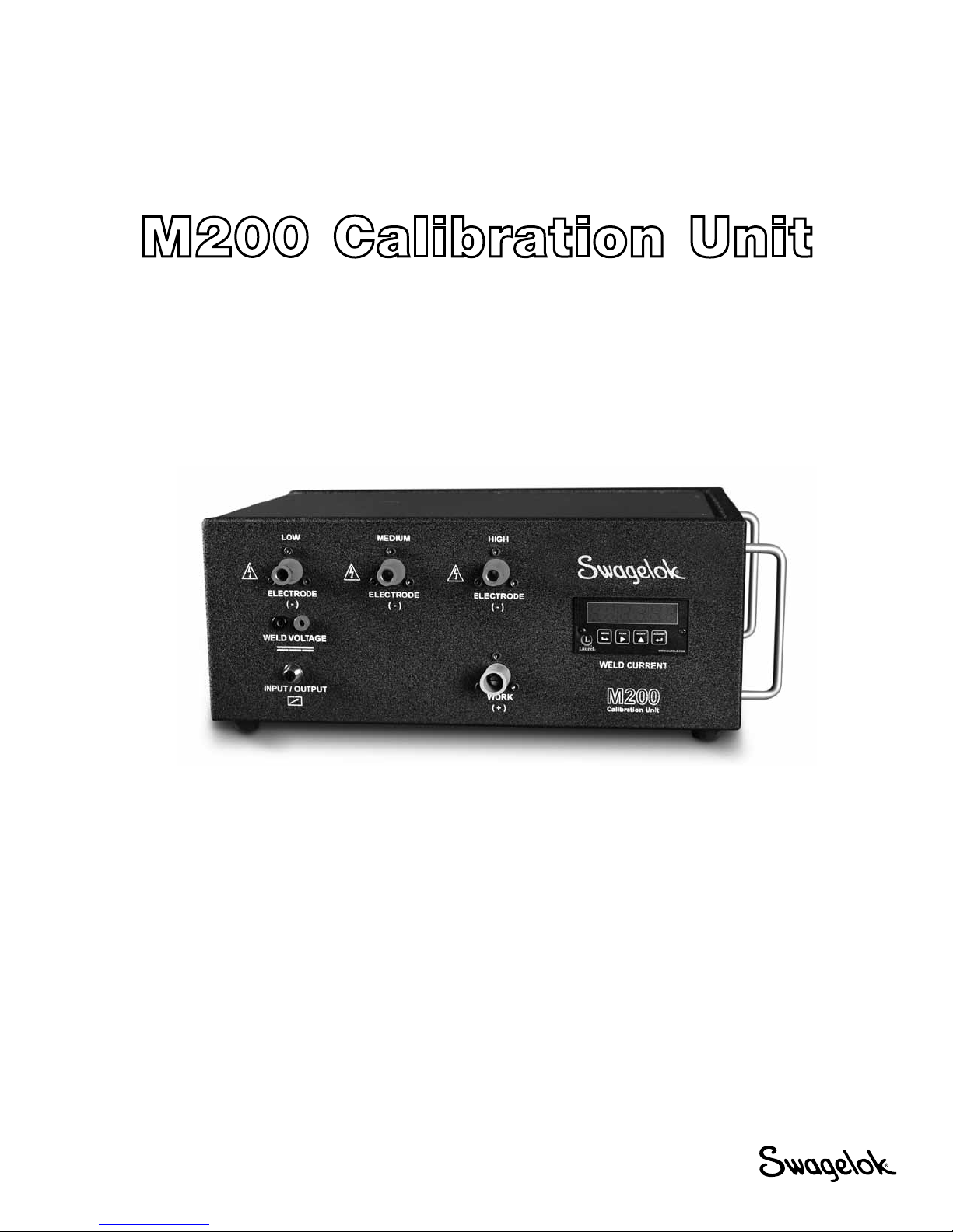
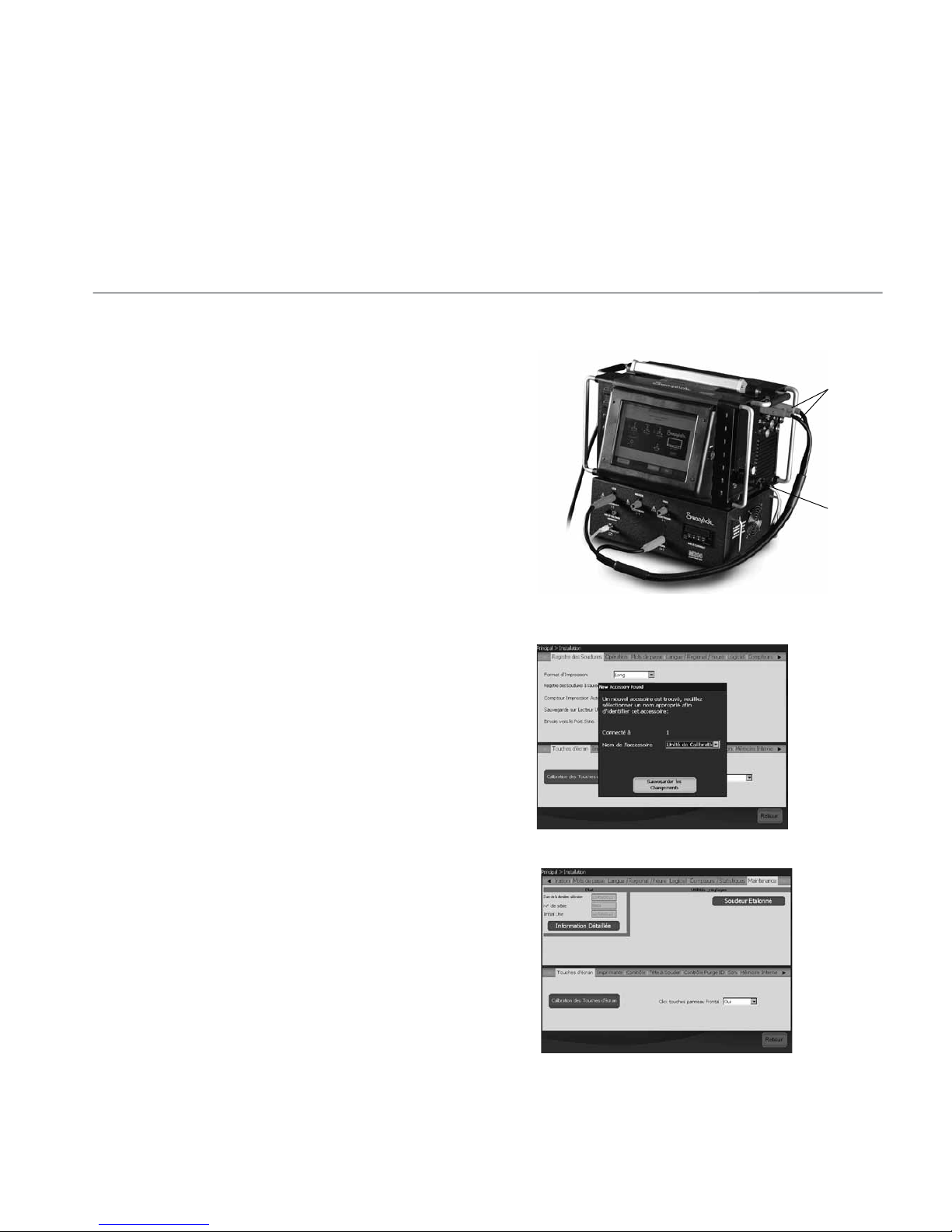
3. Raccordez le faisceau de câbles (entrée/sortie) et les câbles
de soudure à l’alimentation M200 et à l’unité d’étalonnage,
comme cela est indiqué sur la gure1.
Remarque: Effectuez un quart de tour dans le sens des
aiguilles d’une montre avec les connecteurs des
câbles de soudure.
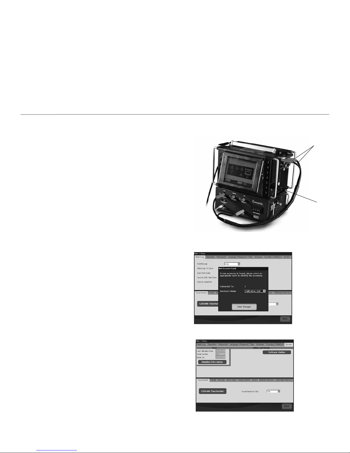
4. Une boîte de dialogue s’afche sur l’écran de l’alimentation
M200. Assurez-vous que «Unité de calibration» est le nom
de l’accessoire gurant dans le menu déroulant. Appuyez sur
Sauvegarder les changements (Fig. 2).
5. Sélectionnez l’onglet Maintenance, puis appuyez sur
Soudeur étalonné. Un message invitant à fournir des
informations s’afche à l’écran. Ces informations seront
utilisées dans le certicat optionnel disponible à la n du
processus d’étalonnage. Il n’est pas obligatoire de fournir
ces informations avant de procéder à l’étalonnage (Fig. 3).
Fig. 2 — Écran «Accessoire »
Fig. 3 — Onglet «Maintenance»
Mentions d’avertissement et symboles de
sécurité utilisés dans cette notice
MISE EN GARDE Indique une situation dangereuse qui, si
elle n’est pas évitée, peut entraîner des
blessures graves voire mortelles.
PRUDENCE Indique une situation dangereuse qui, si
elle n’est pas évitée, peut entraîner des
blessures légères ou modérées.
ATTENTION Indique une situation dangereuse qui, si elle
n’est pas évitée, peut endommager l’outil ou
provoquer d’autres dégâts matériels.
Symbole de sécurité indiquant un risque possible de
blessures corporelles.
Symbole de sécurité indiquant un risque possible de
blessures corporelles causées par un choc électrique.
Fig. 1 — Raccordements de réglage
Câble de
soudure
Faisceau
de câbles

11
Fig. 4 — Onglet «Courant»
Fig. 5 — Instructions affichées sur l’écran
Fig. 6 — Onglet «Voltage»
Étalonnage de la tension
1. Sélectionnez l’onglet Voltage sur l’écran Calibration
soudeur. Un message invitant à fournir des informations
s’afche à l’écran. Ces informations seront utilisées dans
le certicat optionnel disponible à la n du processus
d’étalonnage. Il n’est pas obligatoire de fournir ces
informations avant de procéder à l’étalonnage (Fig. 6).
2. Raccordez un multimètre numérique aux connecteurs
permettant d’étalonner la tension de soudure sur l’unité
d’étalonnage. Vériez que les câbles de soudure et le
faisceau de câbles sont raccordés comme indiqué sur la
gure7.
3. Réglez le multimètre numérique sur la plage 0 à 20volts en
courant continu.
4. Appuyez sur Démarrage.
MISE EN GARDE
Ne débrancher aucun des câbles de l’alimentation
M200 pendant le processus d’étalonnage, en raison
des risques d’électrocution.
5. Effectuez l’étalonnage de la tension en suivant les
instructions afchées sur l’écran.
6. Une fois l’étalonnage terminé, appuyez sur Enregistrer.
Étalonnage de l’intensité
1. Sélectionnez l’onglet Courant sur l’écran Calibration
soudeur (Fig. 4).
2. Vériez que le connecteur rouge est inséré dans la prise
marquée LOW sur l’unité d’étalonnage.
3. Appuyez sur Démarrage.
MISE EN GARDE
Ne pas débrancher les câbles de soudure de
l’alimentation M200 pendant le processus
d’étalonnage, en raison des risques d’électrocution.
ATTENTION
Ne pas brancher ou débrancher la tête à souder
pendant que l’étalonnage est en cours. Cela peut
provoquer une erreur système.
Remarque: L’intensité afchée sur l’unité d’étalonnage doit
se situer dans un intervalle de plus ou moins
0,25ampères autour de la valeur afchée sur
l’alimentation M200. Si ça n’est pas le cas,
reportez-vous à la section Dépannage, ou
prenez contact avec votre représentant agréé
Swagelok.
4. Effectuez l’étalonnage de l’intensité en suivant les
instructions afchées sur l’écran (Fig.5).
Fig. 7 — Branchements pour l’étalonnage de la tension
Câble de
soudure
Faisceau
de câbles
Multimètre

12
Fig. 8 — Onglet «Vitesse»
Vérification de la vitesse des têtes à souder
1. Sélectionnez l’onglet Vitesse sur l’écran Calibration
soudeur (Fig. 8).
2. Raccordez la tête à souder comme indiqué sur la gure9.
3. Saisissez la vitesse que vous souhaitez vérier sur l’écran de
l’alimentation M200.
4. Appuyez sur Démarrage. Le rotor de la tête à souder se
met à tourner, l’alimentation M200 vérie la vitesse, et les
résultats s’afchent sur l’écran.
MISE EN GARDE
Ne pas débrancher la tête à souder de l’alimentation
M200 alors que la vérification de la vitesse est en
cours, en raison des risques d’électrocution.
PRUDENCE
Le rotor commence à tourner lorsque vous appuyez
sur Démarrage. Le rotor constitue un point de
pincement potentiel.
5. Appuyez sur Enregistrer après son activation pour
enregistrer la vitesse afchée. Cette vitesse apparaîtra
sur le certicat optionnel disponible à la n du processus
d’étalonnage. La tête à souder revient à sa position d’origine
lorsque l’on appuie sur Enregistrer.
Fig. 9 — Raccordements pour la vérification de la vitesse
représentés avec le câble adaptateur de tête à souder
optionnel

13
Production du certificat
Un certicat en anglais est produit lorsque les trois opérations
suivantes ont été réalisées: étalonnage du courant, étalonnage
de la tension et la vérication de la vitesse de la tête à souder.
Appuyez sur Information détaillée dans l’onglet Maintenance
pour afcher l’écran Information détaillée. La date du certicat
d’étalonnage sur site correspond à la date à laquelle ces trois
opérations ont été effectuées pour la dernière fois.
Choisissez l’une des méthodes suivantes pour afcher le
certicat:
■
Appuyez sur Afficher. Le certicat s’afche à l’écran (Fig. 10).
■Appuyez sur Imprimer. Une version abrégée du certicat
d’étalonnage sur site s’imprime sur l’imprimante intégrée. La
version complète du certicat ne s’imprime pas.
■Appuyez sur Copier sur clé USB. Le chier du certicat
sera enregistré sur la clé USB connectée à l’alimentation
M200. Le chemin d’accès au chier sur la clé USB sera\
SWS-M200\User Files\Certicate. Le nom du chier se
compose de la date, du numéro de série de l’alimentation
M200 et des mots FieldCalibrationCERT. Exemple:
03/10/2012 M005503 FieldCalibrationCERT.
Pour ouvrir le certicat protégé en écriture, insérez la clé
dans le port USB d’un ordinateur. Il peut ensuite être imprimé
comme un document au format lettre (Fig. 11).
Étalonnage du panneau de mesure
Le panneau de mesure de l’unité d’étalonnage peut être retiré
pour être étalonné si cela est requis par vos prescriptions
d’assurance qualité. Retirez le panneau de mesure de l’unité
d’étalonnage et envoyez-le au fabricant ou à une entreprise
accréditée pour l’étalonnage.
Dépose du panneau de mesure
1. Débranchez l’alimentation M200 et l’unité d’étalonnage.
2. Retirez les câbles de soudure et le faisceau de câbles de
l’unité d’étalonnage.
3. Desserrez les deux vis du panneau de mesure en effectuant
un ou deux tours, puis faites glisser le panneau hors de
l’unité d’étalonnage (Fig. 12).
4. Retirez les ls à l’arrière du panneau de mesure en
dégageant le connecteur à l’aide d’un tournevis plat (Fig.13).
ATTENTION
Ne pas forcer sur le connecteur au risque de
l’endommager.
Installation du panneau de mesure
1. Remettez les connecteurs en place dans le panneau
de mesure conformément aux instructions gurant sur
l’étiquette située sur la face supérieure du panneau.
2. Faites glisser le panneau de mesure dans l’unité
d’étalonnage.
3. Serrez les deux vis sur le panneau de mesure.
Fig. 13 — Connecteurs du panneau de mesure
Connecteur
Fig. 12 — Vis du panneau de mesure
Vis
Vis
SF-07-
T
h
Feature Un
Welding
Amps A
m
Volts V
D
Speed R
P
177, Rev. -, DCN #: 12-
0
h
is certifies that the f
o
its Setting
m
ps
2.0
5.0
10.0
25.0
50.0
75.0
100.0
160.0
D
C 25.0 A
P
M 12.000
0
27395
Cert
o
llowing Swagelok W
in accordance wit
h
Cal
i
Nomina
B
e
Output
E
1.9
4.9
10.0
25.0
50.0
75.1
100.0
162.4
9.9
Eq
S
W
Cu
Vo
l
t
ificate o
f
elding System M200
h
instructions MS-CR
D
i
bration D
a
Model Number
:
Serial Number
:
l AC Input Voltage
:
e
f o r e C a l i b
r
E
rro
r
Tolera
n
-0.1 ± 0.
5
-0.1 ± 0.
5
0.0 ± 0.
5
0.0 ± 0.
5
0.0 ± 1.
0
0.1 ± 1.
5
0.0 ± 2.
0
2.4 ± 3.
2
0.0 ± 0.
5
uipment Used
W
S-M200-CAL
rrent Mete
r
l
t Mete
r
Calibrat
J
o
fField C
a
power supply has be
D
-0198 and M200 A
p
a
te: 2012-
O
:
SWS-M200
:
M5500
220
r
a t I o n
n
ce
A
cceptabl
e
5
YES
5
YES
5
YES
5
YES
0
YES
5
YES
0
YES
2
YES
5
YES
Serial / I.
D
CAL0100
0
25611-02
275a0058
ion Completed B
y
o
e Swagelo
k
a
libratio
en calibrated using t
h
p
plication Software V
e
O
ctobe
r
-2
9
e
? Output
2.0
5.0
10.0
25.0
50.0
75.0
100.0
160.0
9.9
12.000
D
. Number
0
0
y:
n
h
e SWS-M200-CAL
c
e
rsion 2.45.
9
A
f t e r C a
t
Error
T
0.0
0.0
0.0
0.0
0.0
0.0
0.0
0.0
0.0
0.000
c
alibration stand
l i b r a t I o n
T
olerance
A
cc
e
± 0.5
Y
± 0.5
Y
± 0.5
Y
± 0.5
Y
± 1.0
Y
± 1.5
Y
± 2.0
Y
± 3.2
Y
± 0.5
Y
± 0.050
Y
e
ptable?
Y
ES
Y
ES
Y
ES
Y
ES
Y
ES
Y
ES
Y
ES
Y
ES
Y
ES
Y
ES
Fig. 11 — Exemple de certificat d’étalonnage imprimé via un
ordinateur
Fig.10 — Certificat affiché sur l’écran

14
Dépannage
Message
indiquant un
problème Description Solution
Une erreur
inconnue s’est
produite
Étalonnage non terminé pour
une raison inconnue.
Répéter le processus
d’étalonnage. Si
l’erreur se produit à
nouveau, demander
de l’aide à votre
représentant agréé
Swagelok.
Unité
d’étalonnage
non connectée
L’alimentation M200
ne détecte pas l’unité
d’étalonnage.
Vérifier que le faisceau
de câbles et les câbles
de soudure sont
raccordés.
Si tel est le cas, aller
dans l’onglet Réglage/
Fonctionnement de
l’alimentation M200
et s’assurer que
«Unité de calibration»
est sélectionné en
tant qu’accessoire
connecté.
Câbles de
soudure non
connectés
Le câble de soudure n’est pas
raccordé à l’alimentation M200
et à l’unité d’étalonnage.
Raccorder le câble
de soudure à
l’alimentation M200 et
à l’unité d’étalonnage.
Câble de
l’électrode
branché dans
le mauvais
connecteur
Le câble de l’électrode
(rouge) est branché dans le
mauvais connecteur («low»,
«medium» ou «high») sur
l’unité d’étalonnage.
Brancher le câble de
l’électrode dans le
connecteur spécifié
sur l’écran de
l’alimentation M200.
Faisceau de
câbles entrée/
sortie non
connecté
Le faisceau de câbles
(connecteur entrée/sortie)
est raccordé à l’alimentation
M200, mais pas à l’unité
d’étalonnage.
Raccorder le faisceau
de câbles à l’unité
d’étalonnage.
Décalage
maximum
dépassé
L’alimentation M200 est en
train d’effectuer des réglages
en dehors de la plage normale.
Il se peut qu’il y ait des
problèmes avec l’étalonnage
de l’alimentation M200.
Répéter le processus
d’étalonnage. Si
l’erreur se produit à
nouveau, demander
de l’aide à votre
représentant agréé
Swagelok.
Étalonnage non
terminé
L’étalonnage de l’intensité
pour le dernier niveau essayé
n’a pas réussi. Il se peut qu’il
y ait des problèmes avec
l’étalonnage de l’alimentation
M200.
Répéter jusqu’à deux
fois le processus
d’étalonnage. Si
l’erreur se produit à
nouveau, demander
de l’aide à votre
représentant agréé
Swagelok.
Fig. 14 — Message d’erreur

15
M200 Kalibrierungsgerät
Bedienungsanleitung
Mit dem Kalibrierungsgerät werden geliefert:
Schweißkabel Kabelstrang (Eingang/Ausgang) Zwei Bananenbuchsen
SWS-M200-CAL
SWS-M200-CAL-WELD-CABLE SWS-M200-CAL-SENS-WR
Nur für M100 Benutzer
Die Stromabgabe des Netzgeräts M100 lässt sich mit einem optionalen Kabel überprüfen (SWS-M100-CAL-PWR-ADPTR). Mit dem
M200 Kalibrierungsgerät lässt sich keine Kalibrierung des Netzgeräts M100 durchführen. Weitere Informationen erhalten Sie von
Ihrem autorisierten Swagelok Vertreter.
Das M200 Kalibrierungsgerät wird zur Kalibrierung von Stromstärke und Spannung des Swagelok®Netzgeräts M200 sowie zur
Verizierung der Rotorgeschwindigkeit der Swagelok Schweißköpfe eingesetzt. Dadurch können Sie sicherstellen, dass das
Netzgerät innerhalb der Vorgaben funktioniert, ohne es außer Betrieb nehmen zu müssen.
SWS-M200-CAL-VOLT-PLUG
Digitales Multimeter
(repräsentative Illustration)
SWS-M200-CAL-METER

16
Einrichtung
HINWEIS
Zum Durchführen einer vollen Kalibrierung muss das M200
Netzgerät an einer 200 bis 230 V Steckdose angeschlossen
sein.
HINWEIS
Die Kalibrierung des M200 sollte in einer Umgebung
vorgenommen werden, die für den Einsatz von elektrischen und
elektronischen Mess-, Steuer- und Laborgeräten geeignet ist.
1. Stellen Sie sicher, dass die M200 Software-Version 2.50
oder neuer installiert ist. Wählen Sie auf dem Hauptmenü
Einstellungen. Wählen Sie die Registerkarte Software.
Die Anwendungsinformation muss Version 2.5.0.0 oder
höher anzeigen.
2. Zur Aktivierung der Funktionen zur Kalibrierung von
Stromstärke und Spannung ist das Passwort des Besitzer
erforderlich. Wählen Sie Passwörter um das Passwort
einzugeben; weitere Informationen zu Passwörtern
benden sich im M200 Benutzerhandbuch, MS-13-212.
Die Schweißkopfgeschwindigkeit lässt sich auf jeder
Berechtigungsstufe verizieren.
3. Schließen Sie den Kabelstrang (Eingang/Ausgang) und die
Schweißkabel wie abgebildet an das Netzgerät M200 und
das Kalibrierungsgerät an. Abb. 1.
Hinweis: Die Schweißkabelstecker um eine Vierteldrehung
im Uhrzeigersinn drehen.
4. Auf dem M200 Bildschirm erscheint ein Dialogfeld. Stellen
Sie sicher, dass das Kalibriereinrichtung als Name des
Zubehörs auf dem Dropdown-Menü erscheint. Drücken
Sie Änderungen speichern. Abb.2
5. Wählen Sie die Registerkarte Service und drücken
Sie dann auf Schweißgerät abgleichen. Auf dem
Bildschirm erscheint eine Eingabeaufforderung. Die
geforderten Informationen werden für das optionale
Zertikat am Ende des Kalibrierungsprozesses verwendet.
Diese Informationen müssen nicht vor der Kalibrierung
eingegeben werden. Abb. 3
Abb. 2 — Bildschirm Zubehör
Abb. 3 — Registerkarte Service
In dieser Anleitung verwendete Signalwörter
und Sicherheitssymbole
WARNUNG Hinweise auf eine gefährliche Situation,die zu
schweren Verletzungen mit möglicherweise
tödlichen Folgen führen könnte.
VORSICHT Hinweise auf eine gefährliche Situation,die unter
Umständen zu leichteren Verletzungen führen
könnte.
HINWEIS Hinweise auf eine gefährliche Situation, die
unter Umständen zu Geräteschäden oder
anderen Sachschäden führen könnte.
Sicherheitssymbol, das auf potenzielle Verletzungsgefahren
hinweist.
Sicherheitssymbol, das auf potenzielle Verletzungsgefahren
durch Stromschlag hinweist.
Abb. 1 — Einrichtung - Anschlüsse
Schweißkabel
Kabelstrang

17
Abb. 4 — Registerkarte Strom
Abb. 5 — Anleitung auf dem Bildschirm
Abb. 6 — Registerkarte Spannung
Spannungskalibrierung
1. Wählen Sie die Registerkarte Elektrische Spannung
auf dem Bildschirm Schweißabgleich aus. Auf dem
Bildschirm erscheint eine Eingabeauf-forderung. Die
geforderten Informationen werden für das optionale
Zertikat am Ende des Kalibrierungsprozesses verwendet.
Diese Informationen müssen nicht vor der Kalibrierung
eingegeben werden. Abb. 6.
2. Schließen die ein digitales Multimeter an die
Schweißspannungsanschlüsse am Kalibrierungsgerät
an. Stellen Sie sicher, dass die Schweißkabel und der
Kabelstrang wie abgebildet angeschlossen sind. Abb. 7.
3. Stellen Sie das digitale Multimeter auf einen
Spannungsbereich von 0 bis 20 Volt DC ein.
4. Drücken Sie Start.
WARNUNG
Keine Kabel vom Netzgerät M200 entfernen,
während der Kalibrierungsprozess läuft. Es besteht
Stromschlaggefahr.
5. Befolgen Sie zum Durchführen der Spannungskalibrierung
die Anleitung auf dem Bildschirm.
6. Drücken Sie Sichern, wenn Sie fertig sind.
Stromstärkenkalibrierung
1. Wählen Sie die Registerkarte Strom auf dem Bildschirm
Schweißabgleich aus. Abb. 4.
2. Stellen Sie sicher, dass der rote Stecker in dem mit LOW
gekennzeichneten Anschluss am Kalibrierungsgerät
eingesteckt ist.
3. Drücken Sie Start.
WARNUNG
Die Schweißkabel nicht vom Netzgerät M200 entfernen,
während der Kalibrierungsprozess läuft. Es besteht
Stromschlaggefahr.
HINWEIS
Den Schweißkopf während des
Kalibrierungsprozesses nicht anschließen oder
abtrennen. Das könnte zu einem Systemfehler führen.
Hinweis: Die auf dem Kalibrierungsgerät angezeigte
Stromstärke sollten innerhalb von 1/4 Amp. des
auf dem M200 angezeigten Werts liegen. Sollte
dies nicht der Fall sein, gehen Sie zum Abschnitt
Fehlersuche oder wenden Sie sich an Ihren
autorisierten Swagelok Vertreter.
4. Befolgen Sie zum Durchführen der
Stromstärkenkalibrierung die Anleitung auf dem
Bildschirm. Abb. 5.
Abb. 7 — Anschlüsse zur Spannungskalibrierung
Schweißkabel
Kabelstrang
Multimeter

18
Abb. 8 — Registerkarte Geschwindigkeit
Überprüfung der Schweißkopfgeschwindigkeit
1. Wählen Sie die Registerkarte Geschwindigkeit auf dem
Bildschirm Schweißabgleich aus. Abb. 8.
2. Schließen Sie den Schweißkopf wie abgebildet an. Abb. 9.
3. Geben Sie die gewünschte Geschwindigkeit auf dem
Bildschirm des M200 ein.
4. Drücken Sie Start. Der Schweißkopf rotiert und das M200
überprüft die Geschwindigkeit und zeigt das Ergebnis auf
dem Bildschirm an.
WARNUNG
Den Schweißkopfstecker nicht vom Netzgerät M200
entfernen, während die Geschwindigkeitsüberprüfung
läuft. Es besteht Stromschlaggefahr.
VORSICHT
Der Rotor bewegt sich, wenn Start gedrückt wird. Der
Rotor ist eine potentielle Klemmstelle.
5. Nach der Aktivierung Sichern drücken, um die angezeigte
Geschwindigkeit zu speichern. Diese Geschwindigkeit
erscheint auf dem optionalen Zertikat, das am Ende
des Kalibrierungsprozesses erstellt werden kann. Der
Schweißkopf kehrt wieder in die Ausgangsposition zurück,
wenn Sichern gedrückt wird.
Abb. 9 — Anschlüsse zur Geschwindigkeitsüberprüfung
Abbildung mit optionalem Schweißkopfadapterkabel

19
Zertifikatserstellung
Nachdem alle drei Funktionen – Kalibrierung der Stromstärke,
Kalibrierung der Spannung und Überprüfung der
Schweißkopfgeschwindigkeit – ausgeführt wurden, wird ein
englischsprachiges Zertikat erstellt.
Drücken Sie Detallierte Informationen auf der Registerkarte
Service, um den Bildschirm Detaillierte Informationen
anzuzeigen. Als Feldkalibrierungs-Zertikatsdatum wird
das letzte Datum angezeigt, an dem alle drei Funktionen
durchgeführt wurden.
Wählen Sie eine der folgenden Optionen, um das Zertikat
anzusehen:
■Drücken Sie Ansicht. Das Zertikat wird auf dem
Bildschirm angezeigt. Abb. 10
■Drücken Sie Drucken. Eine Kurzversion des
Feldkalibrierungszertikats wird am internen Drucker
gedruckt. Die vollständige Version des Zertikats wird
nicht gedruckt.
■Drücken Sie Zum USB kopieren. Die Zertikatsdatei
wird auf dem am M200 angeschlossenen USB-
Stick gespeichert. Der Dateipfad auf dem USB ist \
SWS-M200\User Files\Certicate. Der Dateiname ist
das Datum, die M200 Seriennummer und die Worte
„FieldCalibrationCERT“, beispielsweise „2012-10-03
M005503 FieldCalibrationCERT“
Den USB-Stick an einen PC anschließen um das
schreibgeschützte Zertikat zu öffnen. Es kann dann
als Dokument im DIN-A4- Format ausgedruckt werden.
Abb.11
Kalibrierung des eingebauten Messgeräts
Das eingebaute Messgerät am Kalibrierungsgerät
kann zur Kalibrierung entfernt werden, falls Ihre
Qualitätssicherungsanforderungen dies erfordern. Das
eingebaute Messgerät vom Kalibrierungsgerät entfernen
und zur Kalibrierung an den Hersteller oder ein zugelassenes
Unternehmen schicken.
Entfernen des eingebauten Messgeräts
1. Den Strom zum M200 und dem Kalibrierungsgerät
abtrennen.
2. Die Schweißkabel und den Kabelstrang vom
Kalibrierungsgerät entfernen.
3. Die zwei Schrauben am eingebauten Messgerät lösen
und das Messgerät aus dem Kalibrierungsgerät schieben..
Abb. 12.
4. Zum Entfernen der Drähte von der Rückseite des
Messgeräts einen achen Schraubenzieher an der Ecke
des Steckerkörpers ansetzen. Abb. 13.
HINWEIS
Dabei keine Gewalt anwenden, damit der Stecker
nicht beschädigt wird.
Installation des eingebauten Messgeräts
1. Die Stecker im eingebauten Messgerät gemäß dem Schild
an der Oberseite des Messgeräts wieder anbringen.
2. Das Messgerät in das Kalibrierungsgerät schieben.
3. Die zwei Schrauben am Messgerät festziehen.
Abb. 13 — Anschlüsse für eingebautes Messgerät
Stecker
Abb. 12 — Schrauben am eingebauten Messgerät
Schraube
Schraube
SF-07-
T
h
Feature Un
Welding
Amps A
m
Volts V
D
Speed R
P
177, Rev. -, DCN #: 12-
0
h
is certifies that the f
o
its Setting
m
ps
2.0
5.0
10.0
25.0
50.0
75.0
100.0
160.0
D
C 25.0 A
P
M 12.000
0
27395
Cer
t
o
llowing Swagelok W
in accordance wit
h
Cal
i
Nomina
B
e
Output
E
1.9
4.9
10.0
25.0
50.0
75.1
100.0
162.4
9.9
Eq
S
W
Cu
Vo
l
t
ificate o
f
elding System M200
h
instructions MS-CR
D
i
bration D
a
Model Number
:
Serial Number
:
l AC Input Voltage
:
e
f o r e C a l i b
r
E
rro
r
Tolera
n
-0.1 ± 0.
5
-0.1 ± 0.
5
0.0 ± 0.
5
0.0 ± 0.
5
0.0 ± 1.
0
0.1 ± 1.
5
0.0 ± 2.
0
2.4 ± 3.
2
0.0 ± 0.
5
uipment Used
W
S-M200-CAL
rrent Mete
r
l
t Mete
r
Calibrat
J
o
f
Field C
a
power supply has be
D
-0198 and M200 A
p
a
te: 2012-
O
:
SWS-M200
:
M5500
220
r
a t I o n
n
ce
A
cceptabl
e
5
YES
5
YES
5
YES
5
YES
0
YES
5
YES
0
YES
2
YES
5
YES
Serial / I.
D
CAL0100
0
25611-02
275a0058
ion Completed B
y
o
e Swagelo
k
a
libratio
en calibrated using t
h
p
plication Software V
e
O
ctobe
r
-2
9
e
? Output
2.0
5.0
10.0
25.0
50.0
75.0
100.0
160.0
9.9
12.000
D
. Number
0
0
y:
n
h
e SWS-M200-CAL
c
e
rsion 2.45.
9
A
f t e r C a
t
Error
T
0.0
0.0
0.0
0.0
0.0
0.0
0.0
0.0
0.0
0.000
c
alibration stand
l i b r a t I o n
T
olerance
A
cc
e
± 0.5
Y
± 0.5
Y
± 0.5
Y
± 0.5
Y
± 1.0
Y
± 1.5
Y
± 2.0
Y
± 3.2
Y
± 0.5
Y
± 0.050
Y
e
ptable?
Y
ES
Y
ES
Y
ES
Y
ES
Y
ES
Y
ES
Y
ES
Y
ES
Y
ES
Y
ES
Abb. 11 — Beispiel eines am PC ausgedruckten
Kalibrierungszertifikats
Abb. 10 — Zertifikat auf dem Bildschirm

20
Fehlerbehebung
Systemmeldung Beschreibung Behebung
Unknown Error
Occurred (Es
kam zu einem
unbekannten
Fehler)
Die Kalibrierung konnte
aus unbekanntem Grund
nicht beendet werden.
Den Kalibrierung-
sprozess wiederholen.
Wenden Sie sich,
falls sich der Fehler
wiederholt, an Ihren
autorisierten Swagelok
Vertreter.
Calibration Unit
Not Connected
(Kalibrierungsgerät
nicht angeschlos-
sen)
Das M200 registriert
nicht, dass das
Kalibrierungsgerät
angeschlossen ist.
Sicherstellen, dass
der Kabelstrang und
die Schweißkabel
angeschlossen sind.
Gehen Sie, wenn
diese angeschlossen
sind, zur Registerkarte
Einrichtung/Betrieb
auf dem M200 und
stellen Sie sicher, dass
"Calibration Unit"
(Kalibrierungsgerät)
als angeschlossenes
Zubehör ausgewählt
ist.
Welding Cables
Not Connected
(Schweißkabel
nicht angeschlos-
sen)
Das Schweißkabel ist
nicht an das M200 und
das Kalibrierungsgerät
angeschlossen.
Das Schweißkabel an
das M200 und das
Kalibrierungsgerät
anschließen.
Electrode Cable
Plugged into
Wrong Connector
(Elektrodenkabel
falsch eingesteckt)
Das Elektrodenkabel
(rot) ist in den falschen
Bereichsanschluss
(niedrig, mittel oder hoch)
am Kalibrierungsgerät
eingesteckt.
Schließen Sie das
Elektrodenkabel
an dem auf dem
M200 Bildschirm
angegebenen
Bereichsanschluss an.
Input/Output
Wire Harness
Not Connected
(Eingang/
Ausgang-
Kabelstrang nicht
angeschlossen)
Der Kabelstrang
(Eingang/Ausgang-
Anschluss) ist am
M200 aber nicht am
Kalibrierungsgerät
angeschlossen.
Den Kabelstrang am
Kalibrierungsgerät
anschließen.
Exceeded
Maximum Offset
(Überschreitung
des maximalen
Versatzes)
Das M200 nimmt
Anpassungen außerhalb
des normalen Bereichs
vor. Eventuell bestehen
Probleme mit der
Kalibrierung des M200.
Den Kalibrierung-
sprozess wiederholen.
Wenden Sie sich,
falls sich der Fehler
wiederholt, an Ihren
autorisierten Swagelok
Vertreter.
Calibration Not
Completed
(Kalibrierung nicht
beendet)
Die für die letzte Stufe
unternommene aktuelle
Kalibrierung war nicht
erfolgreich. Eventuell
bestehen Probleme mit
der Kalibrierung des
M200.
Wiederholen Sie das
Kalibrierungsverfahren
bis zu zwei mal.
Wenden Sie sich,
falls sich der Fehler
wiederholt, an Ihren
autorisierten Swagelok
Vertreter.
Abb. 14 — Fehlermeldung
Other manuals for M200
3
Table of contents
Languages: