Motomaster 011-3003-0 User manual
IMPORTANT:
Please read this manual carefully before running this battery tester INSTRUCTION
MANUAL
and save it for reference.
BATTERY TESTER
model no. 011-3003-0

tabs
continuation tabs
notes
warnings
headline bars
tabs
continuation tabs
notes
warnings
model no. 011-3003-0 | contact us 1-888-942-6686
2
WARRANTY INFORMATION
IF ANY PARTS ARE MISSING OR DAMAGED, OR IF YOU HAVE ANY QUESTIONS,
PLEASE CALL OUR TOLL-FREE HELPLINE AT 1-888-942-6686
Read and understand this instruction manual thoroughly before using the product. It
contains important information for your safety as well as operating and maintenance
advice.
Keep this instruction manual for future use. Should this product be passed on to a third
party, this instruction manual must be included.
This MotoMaster® product carries a one (1) year warranty against defects in workmanship and materials.
At its discretion, MotoMaster® Canada agrees to have any defective part(s) repaired or replaced free of
charge, within the stated warranty period, when returned by the original purchaser with proof of purchase.
This product is not guaranteed against wear or breakage due to misuse and/or abuse.

TABLE OF CONTENTS
headline bars
headline bars
ation tabs
nings
3
TABLE OF CONTENTS
SAVE THESE INSTRUCTIONS
This manual contains important safety and operating instructions. Read all instructions and follow
them with use of this products
4
5
6
7
11
11
SAFETY INFORMATION
KEY PARTS LIST
IMPORTANT INFORMATION
OPERATION
MAINTENANCE
SPECIFICATIONS

tabs
continuation tabs
notes
warnings
headline bars
tabs
continuation tabs
notes
warnings
model no. 011-3003-0 | contact us 1-888-942-6686
4
SAFETY INFORMATION
IMPORTANT
WARNING!
FIRE AND EXPLOSION HAZARD
INTRODUCTION
• Make sure the area around the battery
tester is free from spark or flame when
testing automotive batteries. Doing so
may cause serious damage to vehicle's
electronic circuitry, thereby resulting
in fire or explosion.
• Never smoke when working near a
battery or engine.
• Do not drop a metal tool on the battery,
as doing so can create a spark or short
circuit in the battery or other electrical
parts, resulting in battery explosion.
• Never reverse the connection between
the positive/negative clamps of the
battery tester and battery terminals.
• Do not connect the positive/negative
clamps to battery terminals when the
spring-loaded switch is in the ON position.
• Always operate the battery tester in a
well-ventilated area.
This manual contains information that relates
to PROTECTING PERSONAL SAFETY and
PREVENTING EQUIPMENT PROBLEMS.
Carefully read and follow the guidelines in this
manual and give special attention to the
CAUTION and WARNING statements.
Before using your MotoMaster 100 A Battery
Tester, be sure to read and save these safety
instructions.
®
WARNING!
Read all instructions and follow them with use of this product. Questions?
Call Customer Service Hotline: 1-888-942-6686.
5
1
5
2
4
3
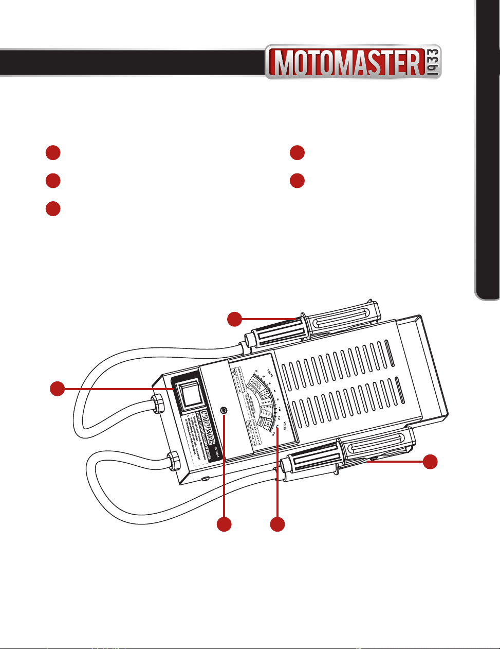
BATTERY TESTER
Red (Positive) Cable Clamp
1
Black (Negative) Cable Clamp
2
Meter Display
3
Spring-loaded Switch
4
Adjustment Screw
5
headline bars
headline bars
continuation tabs
warnings
KEY PARTS LIST
Table of contents
Other Motomaster Test Equipment manuals


Popular Test Equipment manuals by other brands


Redtech
Redtech TRAILERteck T05 user manual

Venmar
Venmar AVS Constructo 1.0 HRV user guide

Test Instrument Solutions
Test Instrument Solutions SafetyPAT operating manual

Hanna Instruments
Hanna Instruments HI 38078 instruction manual

Kistler
Kistler 5495C Series instruction manual

Waygate Technologies
Waygate Technologies DM5E Basic quick start guide

StoneL
StoneL DeviceNet CK464002A manual

Seica
Seica RAPID 220 Site preparation guide

Kingfisher
Kingfisher KI7400 Series Training manual

Kurth Electronic
Kurth Electronic CCTS-03 operating manual

SMART
SMART KANAAD SBT XTREME 3G Series user manual

Agilent Technologies
Agilent Technologies BERT Serial Getting started