Swatch EM Microelectronic EM8500 Series User manual

USER GUIDE ƖEM8500 SERIES
Copyright 2016, EM Microelectronic-Marin SA
EMDVK8500-MN01, Version 2.0, 5-Jul-16
1
www.emmicroelectronic.com
420005-A01, 3.0
EMDVK8500 DEVELOPMENT KIT USER GUIDE
TABLE OF CONTENTS
1INTRODUCTION ..............................................................................................................................................................2
2MAIN FEATURES.............................................................................................................................................................2
3CONTENT DESCRIPTION..................................................................................................................................................3
4INSTALLATION AND SOFTWARE/FIRMWARE UPDATE ....................................................................................................3
4.1 INITIAL INSTALLATION ....................................................................................................................................................3
4.2 SOFTWARE UPDATE .......................................................................................................................................................8
4.3 FIRMWARE UPDATE.......................................................................................................................................................9
5HARDWARE DESCRIPTION OVERVIEW..........................................................................................................................11
5.1 CONFIGURATION MODE ...............................................................................................................................................12
5.2 APPLICATION MODE ....................................................................................................................................................13
5.3 STAND-ALONE MODE...................................................................................................................................................14
6APPLICATION INTERFACE..............................................................................................................................................16
7APPLICATION BOARD ...................................................................................................................................................17
7.1 DESCRIPTION .............................................................................................................................................................17
7.2 SCHEMATIC................................................................................................................................................................19
7.3 BOM ........................................................................................................................................................................20
7.4 INTERNAL MEASUREMENT:A/D ACQUISITION UNIT ...........................................................................................................21
8DAUGHTER BOARD.......................................................................................................................................................22
8.1 OVERVIEW ................................................................................................................................................................22
8.2 INTERNAL MEASUREMENT:A/D ACQUISITION UNIT ...........................................................................................................24
8.3 EXTERNAL MEASUREMENT BY SHUNT RESISTORS................................................................................................................24
8.4 CONNECTIONS FOR EXTERNAL HRV MEASUREMENTS.....................................................................................................25
8.5 CONNECTIONS FOR EXTERNAL LTS MEASUREMENTS..................................................................................................26
8.6 CONNECTIONS FOR EXTERNAL STS MEASUREMENTS.......................................................................................................27
9BASE BOARD ................................................................................................................................................................28
9.1 OVERVIEW ................................................................................................................................................................28
10 EM8500 DEVELOPMENT EXPLORER USER INTERFACE...................................................................................................30
10.1 CONFIGURE MENU DESCRIPTION ....................................................................................................................................31
10.2 MEASURE WINDOW DESCRIPTION ..................................................................................................................................32
10.3 VISUALIZE WINDOW DESCRIPTION ..................................................................................................................................34
10.4 MEASURE AND VISUALIZE WINDOWS -ACQUISITION UNIT INFORMATIONS .............................................................................36
11 TABLE OF CONTENTS ....................................................................................................................................................38
11.1 LIST OF FIGURES .........................................................................................................................................................38
11.2 LIST OF TABLES...........................................................................................................................................................39
EM MICROELECTRONIC - MARIN SA

USER GUIDE ƖEM8500 SERIES
Copyright 2016, EM Microelectronic-Marin SA
EMDVK8500-MN01, Version 2.0, 5-Jul-16
2
www.emmicroelectronic.com
420005-A01, 3.0
1 INTRODUCTION
The EMDVK8500 is a powerful development kit for the configuration, evaluation, prototyping and measurement of
integrated energy harvesting solutions based on EM8500 series.
The development kit offers a complete set of features to characterize and configure your hardware application.
The EMDVK8500 consists of three boards:
•The IPS Base board
•The EMDVK8500 daughter board
•The application board
The EMDVK8500 exists in different variants in order to support the EM8500 series (e.g EM8500, EM8502,…).
2 MAIN FEATURES
Hardware
ƖModular architecture for prototyping, test and
customer application
ƖFlexible load and harvester source selection
ƖReady to measure nodes for lab equipment
(oscilloscope, power analyzer, …)
ƖUp to eight channel high speed acquisition
ƖExpansion header for prototyping and external
connection
ƖApplication board
ƖOn-board EM8500 configuration
ƖEM8500 registers and EEProm configuration
ƖSelf USB powered and stand-alone mode
Software
ƖFriendly GUI
ƖMulti-window environment
ƖUser friendly graphical interface
ƖRegister and EEProm view and configuration
ƖConfigurable connection matrix
ƖSupport for I2C and SPI access
ƖSelectable operation modes
ƖAdvanced real-time energy voltage profile
recording
ƖWaveform display
ƖCursors and zooming capabilities
ƖMonitoring and advanced measurement

USER GUIDE ƖEM8500 SERIES
Copyright 2016, EM Microelectronic-Marin SA
EMDVK8500-MN01, Version 2.0, 5-Jul-16
3
www.emmicroelectronic.com
420005-A01, 3.0
3 CONTENT DESCRIPTION
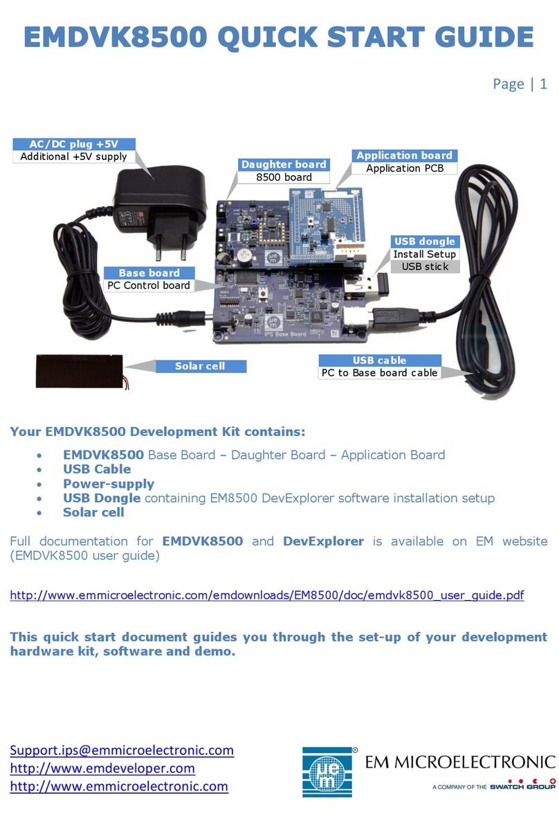
The EMDVK8500 kit consists of:
Ɩ1x Base board
Ɩ1x Daughter board
Ɩ1x Application board
Ɩ1x Memory stick - USB dongle 4GB containing EM8500 DevExplorer software installation setup
Ɩ1x Cable - USB cable type A to B
Ɩ1x Power supply - AC/DC +5V plug
Ɩ1x Solar cell
AC/DC plug +5V
Additional +5V supply
USB cable
PC to Base board cable
USB dongle
Install Setup
USB stick
Application board
Application PCB
Base board
PC Control board
Daughter board
8500 board
Solar cell
Figure 3-1 EMDVK8500 deliverables
Note: In this document the reference name EM8500 refers to the EM8500 series (harvesting family device). In some
particular description the part number is used (e.g EM8500, EM8502,…).
4 INSTALLATION AND SOFTWARE/FIRMWARE UPDATE
4.1 INITIAL INSTALLATION
To install the software EM8500 DevExplorer, an installation setup file is available on the memory stick.
Simply connect the memory stick to the Base board (USB MEM connector) and connect the Base board (USB
Host) to the PC through the USB cable.
Skip and close the installation driver window that may pop-up.
Open an explorer window

USER GUIDE ƖEM8500 SERIES
Copyright 2016, EM Microelectronic-Marin SA
EMDVK8500-MN01, Version 2.0, 5-Jul-16
4
www.emmicroelectronic.com
420005-A01, 3.0
Click on the relevant USB stick drive (EM8500 DevKit)
Double click on the EM8500 DevExplorer setup executable file and accept the installation invitation.
The following installation wizard appears. Click Next.
You can answer No to the following question and check for update later.
Accept the license agreement (Next)

USER GUIDE ƖEM8500 SERIES
Copyright 2016, EM Microelectronic-Marin SA
EMDVK8500-MN01, Version 2.0, 5-Jul-16
7
www.emmicroelectronic.com
420005-A01, 3.0
After installation, the Start Menu now contains the following shortcuts
From this Menu, two update tools are available.
ƖThe shortcut Online Update Check is used to check for new EM8500 DevExplorer software release. Use
this shortcut to check for updates.
ƖThe shortcut Firmware Loader (Third-Party tool) is used to udpate the firmware of the EM8500 base
board.
Each EM8500 DevExplorer software contains a programming Hex file for the Base Board firmware.
Use this shortcut to do the firmware update if required
Note:
In case you decide to directly check for an update during your initial installation (answering yes to the below
message requires that your PC has an active internet connection), the following message will be displayed.
Click Yes.
In the below installation example, an update has been found.
Click Yes.
Then the normal procedure installation needs to be followed. Click OK and follow the normal installation flow.

USER GUIDE ƖEM8500 SERIES
Copyright 2016, EM Microelectronic-Marin SA
EMDVK8500-MN01, Version 2.0, 5-Jul-16
8
www.emmicroelectronic.com
420005-A01, 3.0
4.2 SOFTWARE UPDATE
EM8500 DevExplorer features an Online Update check that allows checking and installing available updates. To
obtain the latest version, use the shortcut “OnLine Update Check” from the EM8500 DevExplorer.
DevExplorer starts checking for updates and downloads them automatically. If a more recent version is available,
the following message will be displayed. Click Yes
Once the download is done, the normal procedure installation needs to be followed. Click Yes and follow the normal
installation flow.

USER GUIDE ƖEM8500 SERIES
Copyright 2016, EM Microelectronic-Marin SA
EMDVK8500-MN01, Version 2.0, 5-Jul-16
9
www.emmicroelectronic.com
420005-A01, 3.0
4.3 FIRMWARE UPDATE
If it isn’t already installed, run the EM8500 DevExplorer setup and plug in the hardware at least once, so drivers are
installed.
The installer has created a firmware directory for you, from which all subsequent steps shall be performed.
Note:
Firmware loader requires installation of MS Visual C++ Libraries which are commonly installed on PCs. If these are
not installed on your PC, you may either download them from Microsoft or install the full Flash Loader Demonstrator
package from ST Microelectronics, part number STSW-MCU005
Follow the steps below to update the firmware.
ƖConfirm that the DevExplorer is closed.
ƖNavigate to the EM8500 DevExplorer start menu entries.
ƖClick on “Firmware Loader (Third-Party tool)” “Flash Loader” to start this tool
ƖAll settings except the COM port are already preset. To identify the correct COM port, use the Device
Manager and check the corresponding “USB Serial Port (COM x)” used.
Select the correct port from the drop-down-field Port Name:
On the IPS Base Board:
Ɩplace the BOOT jumper J108 to select the controller’s boot mode (1) and
Ɩpress the RESET button SW101 - (2).
ƖThe green status LED D103 stops flashing while in boot mode (3)

USER GUIDE ƖEM8500 SERIES
Copyright 2016, EM Microelectronic-Marin SA
EMDVK8500-MN01, Version 2.0, 5-Jul-16
10
www.emmicroelectronic.com
420005-A01, 3.0
SW101 - MCU_RESET
Press button
to enter boot
D103 - MCU_STAT
Chec k that LED stop
blinking (boot mode)
J108 - MCU_BOOT
Place boot jumper for
for firmware update
1
2
3
Figure 4-1 Configure boot mode (firmware update)
ƖThe flash loader tool will guide you through the firmware download process.
It's not recommended to change the pre-configured settings. In case of errors, press the IPS Base Board RESET
button SW101 again (with the BOOT jumper placed) and navigate back to the communication selection tab and
retry.
ƖAfter successfully downloading the new firmware click “Close” to exit the flash loader tool.
ƖRemove the BOOT jumper and power-cycle the IPS Base Board.

USER GUIDE ƖEM8500 SERIES
Copyright 2016, EM Microelectronic-Marin SA
EMDVK8500-MN01, Version 2.0, 5-Jul-16
11
www.emmicroelectronic.com
420005-A01, 3.0
5 HARDWARE DESCRIPTION OVERVIEW
The EMDVK8500 exists in different variants to support each device of the EM8500 series. In this document without specific
description the name 8500 applies for any member of the EM8500 series. Some particular description refers to specific
parts (e.g: EM8500, EM8502,…).
The architecture of the EMDVK8500 is based on the following block diagram
USB USB
Hub
USB
Media Port
USB
Memory Stick
Power
supply
USB
UART
MAIN MCU Level Shifter
ADC
IPS BASE BOARD
EM6819 MCU RF EM9301
BTN, LEDS
APPLICATION BOARD
DAUGHTER BOARD
EM8500
Switch - Relays
+ + + +
LTS
+
STS
POWER
CTRL
HRV
MEAS.
POWER_GROUND
I2C/SPI
I2C/SPI
Figure 5-1 EMDVK8500 System Architecture
The IPS Base board connects the PC to the EMDVK8500 daughter board through USB. The IPS base board contains a
microcontroller (Main MCU) to perform several tasks:
ƖCommunication to the PC (USB)
ƖCommunication to the EM8500 (support for I2C and SPI bus)
ƖADC acquisition (MEAS.)
ƖSwitch and relay control (CTRL)
The EMDVK8500 daughter board is the core of the harvesting system based on the EM8500 device. It features:
ƖSwitches for connecting the harvester source (HRV), the storage elements (Short Term Storage STS - Long Term
Storage LTS)
ƖConnections to the loads (POWER and POWER_GROUND).
ƖSome access to the voltage nodes monitored by MEAS.
ƖMultiple access to the different nodes of the system and shunt resistors (for current or power analysis) for HRV,
LTS and STS
ƖJumpers for configuration
ƖOn board default HRV, STS and LTS with spare position (STS)
ƖAdditional expansion connector to connect external HRV, STS and LTS.

USER GUIDE ƖEM8500 SERIES
Copyright 2016, EM Microelectronic-Marin SA
EMDVK8500-MN01, Version 2.0, 5-Jul-16
12
www.emmicroelectronic.com
420005-A01, 3.0
The application board is the application load of the system. The application board implements an EM6819 8-bit low-power
microcontroller, an EM9301 2.4Ghz Bluetooth Low Energy Controller, push-buttons and LEDs able to implement various
types of low-power applications. The application board can also be removed and replaced by another application board or
the user can connect external elements to the application headers.
Due to its modular architecture and flexible design, the EMDVK8500 is a very versatile system and as such offers a lot of
possibilities to the user. The following operating modes are offered to the user:
5.1 CONFIGURATION MODE
In this mode the Base Board is connected to and powered from the PC over the USB connection. The EM8500
SPI/I2C interface is connected to the Base Board Main MCU and the Base Board can access the EM8500 registers.
The application board is disconnected from the EM8500 lines (Application board doesn’t need to be present). In
this mode the ADC acquisition can be performed.
USB USB
Hub
USB
Media Port
USB
Memory Stick
Power
supply
USB
UART
MAIN MCU Level Shifter
ADC
IPS BASE BOARD
DAUGHTER BOARD
EM8500
+ + + +
LTS
+
STS
POWER
CTRL
HRV
MEAS.
POWER_GROUND
I2C/SPI
Power
supply
PC
Figure 5-2 EMDVK8500 Configuration Mode

USER GUIDE ƖEM8500 SERIES
Copyright 2016, EM Microelectronic-Marin SA
EMDVK8500-MN01, Version 2.0, 5-Jul-16
13
www.emmicroelectronic.com
420005-A01, 3.0
5.2 APPLICATION MODE
In this mode the Base Board is connected to and powered from the PC over the USB connection. The EM8500
SPI/I2C interface is connected to the application board and the EM8500 lines are not connected to the Base Board
Main MCU. In this mode the ADC acquisition can be performed.
USB USB
Hub
USB
Media Port
USB
Memory Stick
Power
supply
USB
UART
MAIN MCU Level Shifter
ADC
IPS BASE BOARD
EM6819 MCU RF EM9301
BTN, LEDS
APPLICATION BOARD
DAUGHTER BOARD
EM8500
+ + + +
LTS
+
STS
POWER
CTRL
HRV
MEAS.
POWER_GROUND
I2C/SPI
PC
Figure 5-3 EMDVK8500 Application Mode

USER GUIDE ƖEM8500 SERIES
Copyright 2016, EM Microelectronic-Marin SA
EMDVK8500-MN01, Version 2.0, 5-Jul-16
14
www.emmicroelectronic.com
420005-A01, 3.0
5.3 STAND-ALONE MODE
In this mode the Base Board is not powered from the PC (no USB over the USB connection) or is even detached
from the other two boards. . The EM8500 SPI/I2C interface is connected to the application board. The application
is running. In this mode ADC acquisitions are not performed.
The corresponding mode isshown on the Figure 5-4 EMDVK8500 Stand-alone Mode with default applicationboard.
EM6819 MCU RF EM9301
BTN, LEDS
APPLICATION BOARD
DAUGHTER BOARD
EM8500
+ + + +
LTS
+
STS
POWER
HRV
POWER_GROUND
I2C/SPI
Figure 5-4 EMDVK8500 Stand-alone Mode with default application board
The other application mode option is the application board without default application board. The user directly
accesses the application header available on the daughter board. The corresponding mode is shown on the Figure
5-5 EMDVK8500 Stand-alone Mode with user application connections.

USER GUIDE ƖEM8500 SERIES
Copyright 2016, EM Microelectronic-Marin SA
EMDVK8500-MN01, Version 2.0, 5-Jul-16
15
www.emmicroelectronic.com
420005-A01, 3.0
USER APPLICATION
CONNECTIONS
DAUGHTER BOARD
EM8500
+ + + +
LTS
+
STS
POWER
HRV
POWER_GROUND
I2C/SPI
Figure 5-5 EMDVK8500 Stand-alone Mode with user application connections

USER GUIDE ƖEM8500 SERIES
Copyright 2016, EM Microelectronic-Marin SA
EMDVK8500-MN01, Version 2.0, 5-Jul-16
16
www.emmicroelectronic.com
420005-A01, 3.0
6 APPLICATION INTERFACE
The application connector APP1 (J104) and APP2 (J107) provides all the connections for the application.
The application board can be connected to APP1 and APP2 or the user can access the connectors APP1 and APP2 and
its test points.
APP 2
1 GND
2 VSUP
3 VDD_HRV
4 VAUX_GND_0
5 VAUX_GND_1
6 VAUX_GND_2
7 3V3
8 N.C.
9 BAT_LOW
10 HRV_LOW
11 WAKE_UP
12 VDD_STS
13 APP_ADC_CHANNEL
14 GND
APP1
1 GND
2 VSUP
3 VAUX_0
4 VAUX_1
5 VAUX_2
6 N.C.
7 N.C.
8 SCL
9 SDA
10 SCLK
11 MOSI
12 MISO
13 CS
14 GND
Figure 6-1 EMDVK8500 Daughter board –application connections APP2 (J107) and APP1 (J104) - top
view
I/O TYPE
DESCRIPTION
NO.
PIN NAME
DIRECTION(*)
SUPPLY
1
GND
Supply
-
System ground connection (EM8500 device ground)
2
VSUP
Input
-
Main supply
3
VAUX[0]
Input
–
Auxiliary 0 supply input connection
4
VAUX[1]
Input
–
Auxiliary 1 supply input connection
5
VAUX[2]
Input
–
Auxiliary 2 supply input connection
6
N.C.
Reserved
7
N.C.
Reserved
8
SCL(*)
Output
VSUP
I2C clock connection
9
SDA(*)
Inout
VSUP
I2C data connection
10
SCLK(*)
Output
VSUP
SPI clock connection
11
MOSI(*)
Output
VSUP
SPI MOSI connection
12
MISO
Input
VSUP
SPI MISO connection
13
CS
Output
VSUP
SPI chip select and SPI/I2C selection mode (when at ‘1’)
14
GND
Supply
-
System ground connection (EM8500 device ground)
Table 6-1 APP1 Pin-out description
(*): DIRECTION is defined from the application point of view
(*): Pin 8 (SCL I2C clock) and Pin 10 (SCLK SPI clock) are connected together on the Base Board.
(*): Pin 9 (SDA I2C data) and Pin 11 (MOSI SPI data) are connected together on the Base Board.
I/O TYPE
DESCRIPTION
NO.
PIN NAME
DIRECTION(*)
SUPPLY
1
GND
Supply
-
System ground connection (EM8500 device ground)
2
VSUP
Output
-
Main supply Output
3
VDD_HRV
Output
–
Connection to the energy harvester
4
VAUX_GND[0]
Input
–
Auxiliary 0 ground connection
5
VAUX_GND[1]
Input
–
Auxiliary 1 ground connection
6
VAUX_GND[2]
Input
–
Auxiliary 2 ground connection
7
3V3
Input
-
+3.3V voltage
8
N.C.
Reserved
9
BAT_LOW
Input
VSUP
Battery low indicator (when at ‘1’)
10
HRV_LOW
Input
VSUP
Energy harvester cell low indicator (when at ‘1’)
11
WAKE_UP
Output
All
Wake-up pin
12
VDD_STS
I/O
–
Connection for the Short Term energy Storage element
13
APP_ADC_CHANNEL
Output
-
Application output for ADC channel acquisition
14
GND
Supply
-
System ground connection (EM8500 device ground)
Table 6-2 APP2 Pin-out description
(*): DIRECTION is defined from the application point of view

USER GUIDE ƖEM8500 SERIES
Copyright 2016, EM Microelectronic-Marin SA
EMDVK8500-MN01, Version 2.0, 5-Jul-16
17
www.emmicroelectronic.com
420005-A01, 3.0
7 APPLICATION BOARD
7.1 DESCRIPTION
A default Application Board is provided with the EM8500 development kit.
The board is equipped with:
ƖAn 8-bit low power microcontroller EM6819F6-B300 in package TSSOP28.
ƖA Bluetooth smart controller, 2.4Ghz RF balun and chip antenna
Ɩ2 push-buttons
Ɩ2 LEDs
ƖAccess to different nodes for ADC measurements
ƖApplication headers APP1 and APP2 and APP_TP
The board dimensions are 50 x 55.3 mm. APP1 and APP2 are Headers with 14 pins each (2.54 mm pitch).
Based on the default application board features, some low power application can be developed. With the on-board
EM9301 wireless device some Bluetooth smart beacon applications can be implemented.
For the details concerning the EM9301 and the EM6819F6-B300, please refer to the corresponding datasheets.
The EM6819 can be programmed and debuggedthrough the X1 connector (GASP connector). To develop EM6819
firmware, load firmware or debug EM6819 firmware the EM6819 development tools need to be used. Contact EM
Microelectronic for more information or visit the EM Microelectronic Marin website
http://www.emmicroelectronic.com.

USER GUIDE ƖEM8500 SERIES
Copyright 2016, EM Microelectronic-Marin SA
EMDVK8500-MN01, Version 2.0, 5-Jul-16
18
www.emmicroelectronic.com
420005-A01, 3.0
APP1
GND
VSUP
VAUX_0
VAUX_1
VAUX_2
N.C.
N.C.
SCL
SDA
SCLK
MOSI
MISO
CS
GND
APP 2
GND
VSUP
VDD_HRV
VAUX_GND_0
VAUX_GND_1
VAUX_GND_2
3V3
N.C.
BAT_LOW
HRV_LOW
WAKE_UP
VDD_STS
APP_ADC_CHANNEL
GND
APP_TP
PA0_TP
PA7_TP
PB0_TP
PB3_TP
PC2_TP
VSUP
VAUX_0
VAUX_1
APP_ADC_CHANNEL
GND
GASP 6819
Connect to
Rlink adapter
to program
or debug
EM6819
K1 - WAKE_UP
WAKE_UP = VDD_STS
when pressed
(default = pulled-down)
K2 - PA7
PA7 (PA7_TP) = Ground
when pressed
(default = HiZ)
JP1 - VAUX_1 - D1
when Jumper JP1 ON
VAUX_1 is connected
to the led D1
D2 - PC5 and PC6
The led D2 is driven
by PC5 and PC6
('1' to lite ON)
JP3 - VDD_HRV
when Jumper JP3 ON
VDD_HRV is connected
to PA0 (PA0_TP)
JP2- APP_ADC_CHANNEL
JP2 position to connect
to APP_ADC_CHANNEL
PB0 (PB0_TP)
D1 current accross
100ohm resistor
Free application
connection
B
Figure 7-1: Application board description

USER GUIDE ƖEM8500 SERIES
Copyright 2016, EM Microelectronic-Marin SA
EMDVK8500-MN01, Version 2.0, 5-Jul-16
20
www.emmicroelectronic.com
420005-A01, 3.0
7.3 BOM
DESIGNATOR.
Part
Quantity
NT1
Chip antenna 2450AT45A100
1
APP2
HEADER 1x14
2
APP_TP
HEADER 1x10
1
BFC1
Balun 2450FB15A0100E
1
C1
100 nF
1
C2
470 nF
1
C3
1 uF
1
C5
100 pF
1
C6
1 uF
1
C7, C8
15 pF
2
C9
100 pF
1
C10
4.7 nF
1
C11
10 nF
1
C12
22pF
1
C13
3.6pF
1
JP1
JP1
1
JP2
HEADER Selection_3 Positions
1
JP3
Jumper JP3
1
K1, K2
Button KRS211
2
L1
12nH
1
R8
470KOhms
1
R9, R10
100Ohms
2
R11, R12
10KOhms
2
U2
EM9301
1
U3
EM6818
1
X1
HEADER 5X2
1
Y1
Quartz 26MHz
1
D1, D2
Led
2
Table 7-1 APP2 Pin-out description
Other manuals for EM Microelectronic EM8500 Series
1
This manual suits for next models
1
Table of contents
Other Swatch Microcontroller manuals
Popular Microcontroller manuals by other brands

Freescale Semiconductor
Freescale Semiconductor FRDM-MC-LVBLDC user guide

SiFive
SiFive E31 manual

Kent-Moore
Kent-Moore J-46079-30 Upgrade instructions

Freescale Semiconductor
Freescale Semiconductor QE128 Quick reference user guide

Freescale Semiconductor
Freescale Semiconductor MPC5553 Reference manual

THORLABS
THORLABS ELL8 Series manual