manuals.online logo
Brands
  1. Home
  2. •
  3. Brands
  4. •
  5. SWEEX
  6. •
  7. UPS
  8. •
  9. SWEEX BC200010 User manual

SWEEX BC200010 User manual

English version
3
Specifications
Model 1000VA 2000VA 3000VA
Capacity W 600W 2000W 2000W
Input Voltage 120VAC or 220/230/240VAC
Voltage Range Acceptable Voltage Range 0-160VAC / 0-300VAC
Line Low Transfer 88VAC ± 4% or 160/168/175VAC ± 4%
Line Low Comeback 95VAC ± 4% or 170/178/198VAC ± 4%
Line High Transfer 148VAC ± 4% or 260/272/275VAC ± 4%
Line High Comeback 141VAC ± 4% or 248/260/265VAC ± 4%
Output Voltage 120VAC or 220/230/240VAC
Voltage Regulation (Batt. Mode) ±7% RMS for entire battery voltage range
Frequency 50Hz or 60Hz
Frequency Regulation (Batt. Mode) ±0.5Hz
Waveform Pure Sinewave
Transfer Time Typical 4-6ms
Battery Rack Case Battery Type 12V/9Ah 12V/9Ah 12V/7Ah
Battery Number 2 4 8
Backup Time (at full load) 5 minutes (Typical)
Recharge Time 4 hours to 95% after discharged
Indicators AC Mode Green LED lighting
Backup Mode Green LED flashing
Boost/Buck Yellow LED lighting
Load/Battery Level It represents Load Level in AC Mode and Battery Level in Backup Mode
Load/Battery Level 4-segment LED bar- 0-25% : 4th LED lighting
26%-50% : 3rd and 4th LEDs lighting
76%-100% : 4 LEDs in a row all lighting
UPS Fault The 2nd LED in a row of Load/Battery LEDs flashing once every second
and one or more addition load/battery level LEDs lighting
Overload The 1st LED in a row of Load/Battery LEDs flashing once every 0.5 second
and all other load/battery level LEDs lighting
Low Battery The bottom LED in a row of Load/Battery LEDs flashing every 2 seconds
Audible Alarm Backup Mode Sounding every 10 seconds
Low Battery Sounding every 5 seconds
UPS Fault Sounding continuously
Overload Sounding every 0.5 second
Battery Replacement Sounding 2 seconds every 60 seconds
Physical Rack Case Dimension (DxWxH) mm 475x482x85 475x482x130 475x482x172**
Net weight (kg) 18 27.2 45.6
Environment Operating Environment 0- 40°C, 0-90 % relative humidity (non-condensing)
Noise Level Less than 45dB
Interface RS-232 / USB depends of model Support Windows 98SE / 2000/ XP
English version
WWW.SWEEX.COM
2
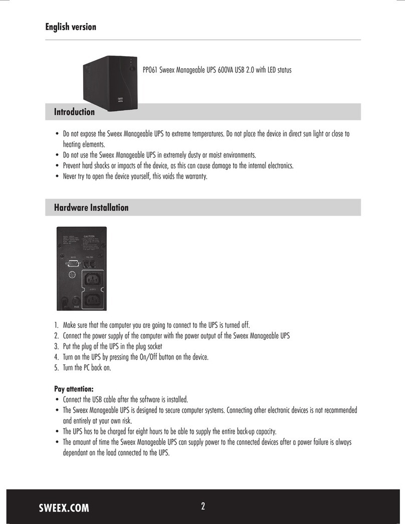
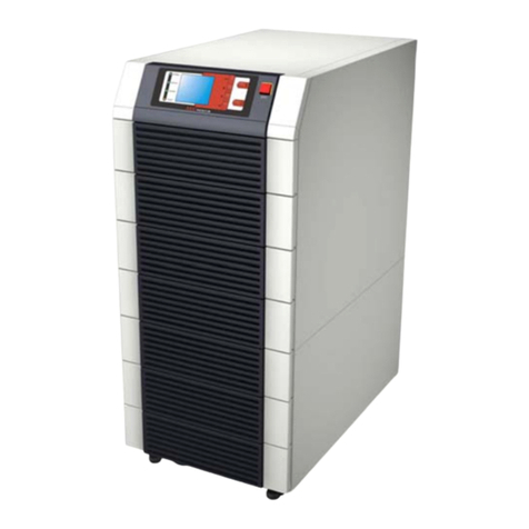
BC200010 Sweex Rackmount 19” UPS 1000VA
Introduction
Thank you for buying this Sweex Rackmount 19“ UPS. This Sweex Rack-mount 19“ UPS works quickly and simply and includes the following
features:
•Backup for servers/systems that must not go down without warning.
•A scheduler to switch the UPS on and off.
•A scheduler to test the rechargeable batteries.
•Multilingual software: English, German, Spanish, Italian, French and Portuguese.
•An e-mail or SMS can be sent in the event of a fault in the mains.
•Send broadcast messages to a group of users in the event of a fault.
We advise you to read this manual carefully first to guarantee correct operation of the Sweex Rack-mount 19“ UPS.
Before starting installation, make sure that the operating system is up-to-date. This is simple to check in Internet Explorer by selecting Windows
Update in the Tools menu.
Contents of the packaging
Before installation, check that all the necessary parts are present. The box should contain the following parts:
•Sweex Rack-mount 19“ UPS
•This manual
•Installation CD-ROM with any drivers, software and a comprehensive manual
Contact the supplier if any of the above parts is missing.
English version
5
English version
WWW.SWEEX.COM
4
System requirements
•A free RS-232 or USB port
•At least 500 MHz processor
•At least 256 MB RAM
•At least 50 MB free disk space
•Microsoft Windows 98SE, 2000 or XP
Installation
Placement
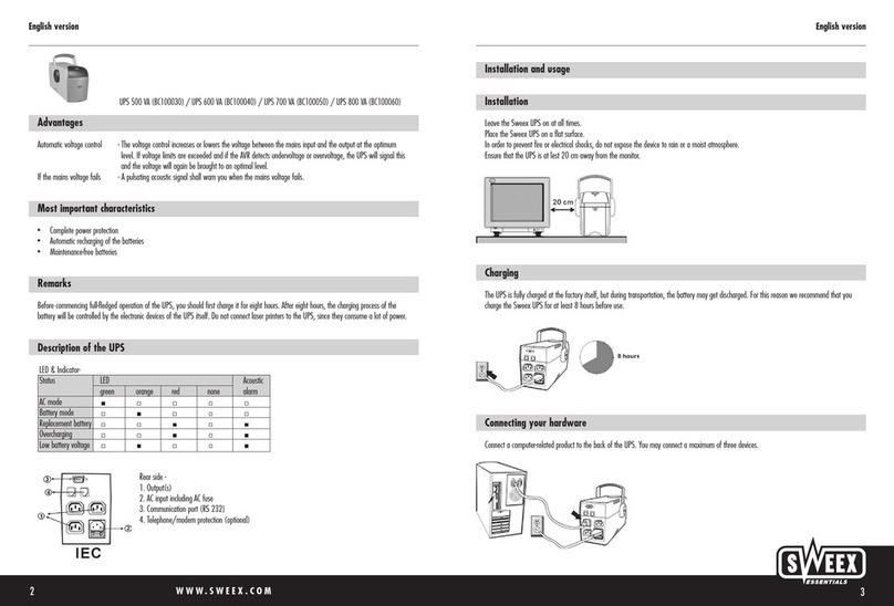
Locate the UPS where it cannot be accidentally disconnected. Locate it in an area with unrestricted airflow, away from water, flammable liquids,
gases, or corrosives. Maintain a minimum of 100mm (4 “es) clearance around the UPS. Maintain an ambient temperature range of 0°C to
40°C (32°F to 104°F)
Before connection
Shutdown load equipment, turn off main supply and unplug load equipments power input cable from main supply socket.
UPS connection for 1000VA
Unplug power input cable from load equipments input socket and plug it into UPS input socket. Re-plug the power input cable into mains supply
socket.
Load connection
Connect the supplied IEC320-10 output cable between the load equipment input socket and one of the UPS AC output socket. Connect all load
equipment to the UPS in the same way.
Turn on
Turn on the UPS by pressing the power switch for at least 0.5 second; then turn on the connected load equipment. The UPS is ready for normal
operation.
System description
Power switch
The power switch controls output power to connected loads.
CAUTION: Pressing the power switch when AC mains is not present will cause the UPS to begin operating from battery. This should not be
performed unless the UPS input is connected to a properly earthed socket.
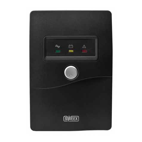
Battery status indicator (green LED)
An illuminated LED indicates the power button is on and main power is available. Green LED flashing 5 times along with an alarm signifies main
voltage is out of specification and UPS is operating in battery mode.
Boost and buck AVR indicator (yellow LED)
An illuminated LED indicates the UPS is correcting main power, due to a mains overvoltage or undervoltage condition.
Load/Battery Level Indicators (all green LEDs)
The Load/Battery Level Indicators have dual functions. During normal mode operation, LED indicators display electrical load placed upon the
UPS; and during battery mode operation, LED indicators display battery
capacity remaining. Each LED designates a 25% load or battery capacity increment. All four LED indicators illuminate at full load/battery
capacity. If the UPS becomes loaded beyond full rating, the top LED indicator will flash continuously while an alarm sounds.
Fault indicator (green LED)
The Fault Indicator is the second bottom LED (contained in load/battery level indicators). A flashing LED indicates the UPS has detected a
problem. An alarm sounds to alert that the UPS requires attention.
Alarm Silence/Battery Test Button
The Alarm Silence/Battery Test Button serves a dual purpose. During normal mode operation, press button for at least one half second to test
capacity of the battery system. The UPS will operate in battery mode for approximately 15 seconds. The illuminated LED indicators in
Load/Battery Level determine battery mode capacity in 25% increments.
During battery mode operation or active alarm condition, this button functions as the alarm silence feature. The low battery alarm is the single
alarm that cannot be silenced. During a Battery Test, if the top two LEDs do not illuminate, allow the UPS to recharge the batteries for 24 hours.
English version
7
Battery mode operation
Battery mode occurs in event of extreme input voltage condition or complete mains failure. The battery system along with the bi-directional
converter generates power for the connected load.
During battery mode an alarm sounds every 10 seconds. This will change to 2 beeps every 5 seconds when battery runs low (approximately 2
minutes remaining). Each load/battery level indicator represents a 25% capacity level. As capacity decreases, fewer indicators remain
illuminated.
Battery mode supports a full rated load for approximately 5 minutes before it shuts down. To increase this time, turn off non-essential pieces of
equipment.
WARNING: Turning off the UPS while in battery mode will result in loss of output power.
The figure below displays approximately 51% - 57% battery capacity remaining.
Battery charge mode
The UPS resumes normal operation once main power is restored, whether the UPS is ON or OFF. At this time, the bi-directional converter begins
recharging the battery.
Battery replacement
CAUTION: A battery can present a risk of electrical shock and high short circuit current. Do not open or mutilate the batteries. Released electrolyte
is harmful to skin and eyes and may be toxic. When replacing the batteries, use the appropriate replacement battery kit. Proper disposal of
batteries is required.
Precautions to be observed before replacing the batteries:
•Turn off and disconnect the UPS from utility power prior to opening the battery replacement door.
•Remove rings, watches, and other metal objects.
•Use a cross-head screwdriver with insulated grips.
•Do not lay tools or other metal objects on top of the batteries.
•If the battery replacement kit is damaged in any way or shows signs of leakage, contact your dealer immediately.
•Do not dispose of batteries in a fire. The batteries may explode.
•If you feel unqualified to replace the battery, do not open the battery door. Call the dealer immediately.
English version
WWW.SWEEX.COM
6
Audible alarm condition
Condition Alarm
Battery Mode(Power Failure) One short beep every 10 seconds; more than 2 minutes of run time remaining
Low Battery Two short beeps every 5 seconds; less than 2 minutes of run time remaining
Battery Replacement 2-second beep every minute
Overload One short beep every second
UPS fault Continuously Sounding
Operation
Normal mode operation
During normal operation, main power provides energy to the UPS. The filters and the power conditioning circuit process this power to provide
computer grade power to connected loads. The UPS maintains the batteries in a fully charged state.
The front panel displays the percentage of load on the UPS output. The figure below indicates approximately 51% - 75% loading.
Mains high/low mode operation
If high or low voltage conditions occur, the UPS will automatically correct the mains voltage by either lowering or raising the input voltage
condition.
The figure below indicates approximately 51% - 57% loading while automatically correcting the mains voltage.
English version
9
Guarantee
All articles supplied under the name Sweex Essentials are covered by a three-year warranty with the exception of Sweex digital still and video
cameras for which the warranty is two years. Rechargeable batteries are covered by a six-month warranty.
Warranty work must only be handled via the dealer where the article was bought.
English version
WWW.SWEEX.COM
8
Safety
WARNING: Do not attempt to service this product yourself except to replace the battery. Opening or removing the cover may expose you to
dangerous voltages, even when the AC cord is disconnected from the electrical outlet. Refer all servicing to qualified service personnel.
This product is designed for Commercial/Industrial use only. It is not intended for use with life support and other designated “critical” devices.
Maximum load must not exceed that shown on the UPS rating label.
The main supply socket or means of isolation must be within 2 meters of the equipment and accessible to the operator. The UPS is designed for
data processing equipment.
The UPS comes with two output power leads with molded connectors. Do not modify the output power leads. Consult dealer if connector does not
match the load socket. UPS must be earthed at all times while in use. Turn UPS off before unplugging it, or the safety earth will be removed.
The 1000VA model is not supplied with an input power lead for connection to the mains supply socket. Use the input mains supply power lead
from you data processing equipment to connect the UPS to the main supply.
CAUTION: The UPS and connected load total earth leakage current must not exceed 3.5 milliamperes If the connected load earth leakage current
is likely to exceed 2.5 milliamperes or you are unsure, then convert the input lead attachment to either a fixed wiring installation or an industrial
plug/socket. This task should be carried out by a competent electrical engineer.
The UPS output supply sockets may electrically live whenever the input power lead is plugged into the mains supply socket. Turning the UPS off
does not electrically isolate the internal parts. To isolate the UPS, turn the UPS off and then isolate it from the main supply.
When installing the UPS or making input and output connections, comply with relevant safety standards.
This equipment complies with requirements of the EMC Directive 89/336/EEC and the published technical standards. Continued compliance
requires installation in accordance with these instructions and the use of manufacturer approved accessories with output cables not exceeding 10
meters (30 ft.) in length. Use a shielded cable for the external communications interface.
Operate UPS only from a properly earth, 50Hz or 60Hz, 220-240 VAC mains supply.
Route power supply leads so they are not walked on or p”ed.
Never block or insert any object into the ventilation holes or other openings. Maintain a minimum clearance of 100mm (4 “es) all around the
UPS for proper airflow and cooling.
Operate the UPS in an indoor environment only, with an ambient temperature range of 0°C to 40°C (32°F to 104°F). Install it in a clean
environment, free from moisture, flammable liquids, gasses, or corrosive substances.
Storing magnetic media on top of the UPS may result in data loss or corruption.
Turn the UPS off and unplug the UPS before cleaning. Use only a soft cloth, never liquid or aerosol cleaners.
This equipment can be operated by individuals without previous training.
CAUTION: The UPS is heavy. Take proper precautions when lifting or moving it.
Please consult the English manual on CD if you require more information.

Other SWEEX UPS manuals

SWEEX PP220 User manual

SWEEX

SWEEX PP220 User manual

SWEEX PP161 - QUICK_START_GUIDE User manual

SWEEX

SWEEX PP161 - QUICK_START_GUIDE User manual

SWEEX PP200 User manual

SWEEX

SWEEX PP200 User manual

SWEEX PP121 - QUICK_START_GUIDE User manual

SWEEX

SWEEX PP121 - QUICK_START_GUIDE User manual

SWEEX PP210 User manual

SWEEX

SWEEX PP210 User manual

SWEEX PP100 User manual

SWEEX

SWEEX PP100 User manual

SWEEX Line Interactive 500 User manual

SWEEX

SWEEX Line Interactive 500 User manual

SWEEX PP300 User manual

SWEEX

SWEEX PP300 User manual

SWEEX PP061 - QUICK_START_GUIDE User manual

SWEEX

SWEEX PP061 - QUICK_START_GUIDE User manual

Popular UPS manuals by other brands

Tecnoware EVO 3.0 RT user manual

Tecnoware

Tecnoware EVO 3.0 RT user manual

PROLiNK INSPIRE 703SFC user guide

PROLiNK

PROLiNK INSPIRE 703SFC user guide

Energenie EG-UPS-021 user manual

Energenie

Energenie EG-UPS-021 user manual

INFOSEC UPS SYSTEM Z1 ZenCube EX Series user manual

INFOSEC UPS SYSTEM

INFOSEC UPS SYSTEM Z1 ZenCube EX Series user manual

CyberPower OL6000RT3U user manual

CyberPower

CyberPower OL6000RT3U user manual

CyberPower CyberShield CSN27U12V-NA3-G user manual

CyberPower

CyberPower CyberShield CSN27U12V-NA3-G user manual

Vertiv LIEBERT PSI5 Series Quick installation user's guide

Vertiv

Vertiv LIEBERT PSI5 Series Quick installation user's guide

Falcon ED-1000-1 user guide

Falcon

Falcon ED-1000-1 user guide

Toshiba 1600EP Series Quick instillation guide

Toshiba

Toshiba 1600EP Series Quick instillation guide

LEGRAND PREMIUS 7.5kVA user manual

LEGRAND

LEGRAND PREMIUS 7.5kVA user manual

CyberPower OP850 Specification sheet

CyberPower

CyberPower OP850 Specification sheet

Eminent Ewent EW3940 user manual

Eminent

Eminent Ewent EW3940 user manual

Chloride Desk POWER 300 operating manual

Chloride

Chloride Desk POWER 300 operating manual

CyberPower PR1500LCDRTXL2U user manual

CyberPower

CyberPower PR1500LCDRTXL2U user manual

Always “On” UPS M4101 installation manual

Always “On” UPS

Always “On” UPS M4101 installation manual

Njoy Garun 30KL user manual

Njoy

Njoy Garun 30KL user manual

CyberPower UT1050EG quick start guide

CyberPower

CyberPower UT1050EG quick start guide

CyberPower CP1350PFCLCD user manual

CyberPower

CyberPower CP1350PFCLCD user manual

manuals.online logo
manuals.online logoBrands
  • About & Mission
  • Contact us
  • Privacy Policy
  • Terms and Conditions

Copyright 2025 Manuals.Online. All Rights Reserved.