SWELL CATAMARANS Shadow User manual

SHADOW ASSEMBLY INSTRUCTIONS
SWELL CATAMARANS
Shadow
Assembly Instructions

SHADOW ASSEMBLY INSTRUCTIONS
SWELL CATAMARANS
Shadow Assembly Instructions
Disclaimer
While the content of this document arises from careful study, the author cannot in any
way guarantee the suitability of any recommendations made, and shall not be under legal
liability of any kind in respect of or arising from the content of this document or any error
therein, or the reliance of any person thereon.
The author makes no representations or warranties, express or implied, of any type
whatsoever.
Author: Tim Swinburn
Draft 3.0, September 2002
©Loday White Ltd
160 Tower Street, Brightlingsea, Essex, UK
Loday White Ltd (UK): Phone +44 (0)7050 260201 • E-mail reg@swell-catamarans.co.uk
Loday White Ltd (France): Phone +33 (0)240 623 555 • E-mail yves@swell-catamarans.co.uk
http://www.swell-catamarans.co.uk
Page i

SHADOW ASSEMBLY INSTRUCTIONS
Table of Contents
Introduction 3
Hulls & trampoline 5
Trampoline 5
Spinnaker blocks 6
Dolphin striker 6
Mast 7
Spreaders & diamond wires 7
Main halyard 9
Rigging the mast 9
Raising the mast 11
Trapeze adjusters 12
Mast rake and rig tension 12
Mast rotation 14
Mainsail downhaul 14
Boom 14
Lowering the mast 15
Mainsail 17
Batten tension 17
Hoisting the mainsail 17
Downhaul 18
Outhaul 18
Mainsheet 18
Traveller 18
Lowering the mainsail 19
Spinnaker 21
Outhaul, halyard, downhaul, sheets 21
Hoisting the spinnaker 24
Dropping the spinnaker 25
Foils 27
Daggerboards 27
Rudders 27
Crossbar & tiller 27
Maintenance 29
Before every sail 29
After every sail 29
Periodically 29
Annually 29
Parts and accessories 31
Accessories 31
Spare Parts 31
Page ii

SHADOW ASSEMBLY INSTRUCTIONS
PAGE INTENTIONALLY BLANK

SHADOW ASSEMBLY INSTRUCTIONS
I
T
b
s
K
T
ntroduction
he Shadow is a single-handed catamaran with mainsail and spinnaker. It has
een designed for high-performance sailing. The boat uses simple control
ystems and high quality fittings, with the lightweight hulls constructed from
evlar foam sandwich for maximum durability.
hese Assembly Instructions are intended to assist you in assembling the
Shadow, provide guidance with initial settings and make recommendations for
sailing the boat.
Sectio
n
1
These two icons indicate vital information for the safe
assembly and use of your Shadow, or suggested settings
from Yves Loday or Tim Swinburn.
ICON KEY
Vital information
Suggested setting
Vital statistics
SCHR handicap 1,07
Portsmouth yardstick 723
LOA 4,80 m
Width 2,40 m
Spinnaker 9,90 m2
Mainsail 12,95 m2
Mast height 8,0 m
Weight (ready to sail) 99,0 kgs
Hull construction Kevlar ™foam sandwich
Page 3

SHADOW ASSEMBLY INSTRUCTIONS
PAGE INTENTIONALLY BLANK
Page 4
SHADOW ASSEMBLY INSTRUCTIONS
Hulls & trampoline
The hulls and beams are supplied ready assembled, with the following tasks
required before sailing the boat for the first time.
Trampoline
The boat is supplied with the trampoline and spinnaker chute fitting attached
to the front beam. To ensure even tension the trampoline is secured and
tensioned by five ropes: two cords which feed from the front beam through
the trampoline to the rear beam, by a securing rope from the rear of the
trampoline to the rear beam, and by two spinnaker block ropes from the side
of the trampoline to the hulls.
Sectio
n
2
1. Unroll the trampoline from around
the front beam and attach the two
trampoline cords to the hasps on
each side of the rear beam. Tension
each of the cords in turn, and secure
with half-hitches.
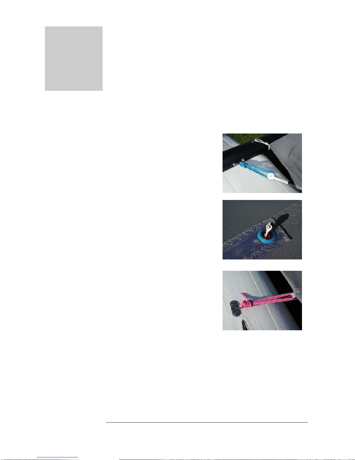
2. Feed one of the spinnaker block
ropes down through the eye in the
trampoline, so that the spinnaker
block shackle is above the
trampoline.
3. Feed the spinnaker block rope
through the stainless fitting by the
daggerboard, then through the
webbing loop on the side of the
trampoline. Fully tighten the rope and
secure with half hitches.
4. Repeat steps 2. and 3. for the second
spinnaker block rope.
5. Feed the trampoline tube through the rear of the trampoline. Attach the
rear trampoline securing rope to the centre of the tube so that the
trampoline can be tensioned outwards from the centre to each side.
6. Feed one half of the trampoline securing rope around the hasps on the rear
beam and the trampoline tube, as shown in the picture; secure with half-
hitches. Repeat for the other half of the trampoline securing rope.
Page 5
SHADOW ASSEMBLY INSTRUCTIONS
7. Tension the trampoline by pulling through all of the slack in the rear
trampoline securing rope, working
from the centre out to each side of
the trampoline. This may need to be
repeated several times to fully
tension the trampoline.
8. Re-tension the two trampoline
cords on each side of the rear beam,
to take up any slack.
9. Re-tension the two spinnaker block ropes, to take up any slack.
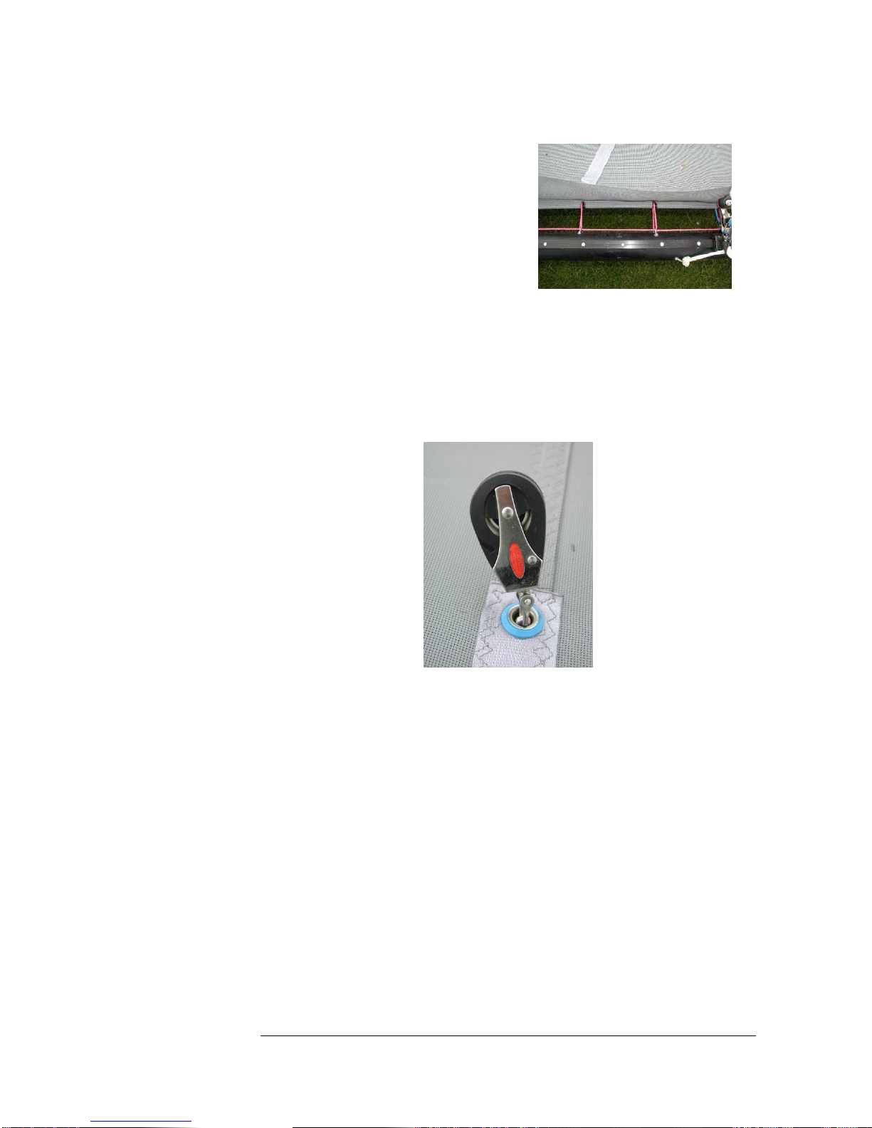
Spinnaker blocks
10. Attach the auto-ratchet spinnaker blocks to the shackles in the trampoline.
The pressure at which the ratchet mechanism engages in the spinnaker
blocks is adjustable, by turning the nut at the end of the block.
Dolphin striker
The dolphin striker below the front beam must be tensioned to resist
downwards pressure from the mast and rig during sailing.
11. There is an adjuster nut and a lock nut, which should both be loosened to
ensure that there is no dolphin striker tension already applied, then adjust
the first nut until it is just finger tight on the dolphin striker.
12. Make a mark on the thread above the nut (with a permanent marker), and
then tension the adjuster nut with a spanner until the mark is
approximately 6mm above the nut.
13. Lock the adjuster nut in place by tightening the lock nut down onto it.
Page 6

SHADOW ASSEMBLY INSTRUCTIONS
Page 7
M
T
s
w
c
p
B
C
A
ast
he rotating Shadow mast uses a lightweight aluminium extrusion, with
trength and gust response provided by adjustable spreaders and diamond
ires. A mast spanner on the base of the mast controls mast rotation, with
ontrol lines led to the sides of the boat. A powerful downhaul system
rovides control over mainsail shape and power, with control lines led to the
side of the boat.
Sectio
n
3
Spreaders & diamond wires
Spreader rake and diamond wire tension determines the response of the mast
(and therefore the mainsail) to gusts
and to crew weight. If the spreader rake
and diamond wire tension are set
correctly the mast shape will remain
stable and powerful to a suitable point
for your crew weight; then as the wind
becomes too powerful the forces in the
rig will exceed the supporting tension
of the diamond wires and the mast will
flex and start to de-power the rig.
The Shadow has three settings for spreader rake, selected by the clevis pins
attaching the rear of the spreaders to the mast.
A. Maximum power (spreaders fully
forward): suitable for heavier
crews, or light winds.
B. Medium power: suitable for most
crews and wind conditions.
C. Minimum power (spreaders fully
raked): suitable for lighter crews
or strong winds.
My spreaders
weight well. I
can still manag
are in the ‘B’ position, which suits my (75 kg)
am fully powered up in 15 knots of breeze, but
e the boat in force 5 gusting 6 conditions.
Attaching spreaders & diamond wires
1. Set the spreaders in your desired position, taping the split rings for security.
2. Hook the top diamond wire fittings into the key-holes in the sides of the
mast.

SHADOW ASSEMBLY INSTRUCTIONS
3. Attach the turnbuckle at the bottom of the diamond wires to the shackle
on the front of the mast, taping the split ring for security.
4. Tension the diamond wires with the turnbuckle, until the mast prebend is
approximately 38mm (1.5”) – this can be measured by pulling a thin cord
tight between the tip and bottom of the mast and measuring the distance
from the cord to the mast track.
5. Once the correct prebend is achieved, look down the mast track from the
tip. If the mast bends to one side, unfasten the diamond wires and reverse
the diamond wires then repeat step 4; if this doesn’t cure the bend some
packing will be needed on one diamond wire. Slacken the diamond wires
and fit a piece of packing (e.g. a discarded rivet stem or similar diameter
piece of stainless steel) between the spreader and diamond wire. Re-tension
the diamond wires until the prebend is approximately 38mm (1.5”), then
look down the mast track and check for any bend. Repeat with different
diameter packing until the mast is straight.
6. S
C
h
lacken the diamond wires and use silicone sealant to
OMPLETELY fill the holes where the top diamond fittings
ook into the sides of the mast.
7. R
a
s
p
s
a
e-tension the diamond wires until the prebend is
pproximately 38mm (1.5”). Use silicone sealant to completely
eal around the diamond fittings, then secure the small
rotective plastic covers over the diamond fittings with
ilicone sealant. Take care that the diamond fittings are
bsolutely sealed in the mast, since any gaps will allow water
into the mast and make capsize recovery difficult.
8. U
s
f
s
se rigging wire to secure the diamond wires into the
preaders. Use PVC tape around the spreader ends and the
ront of the spreaders, to reduce the risk of snagging the
pinnaker.
Page 8
Table of contents
Popular Boat manuals by other brands


Jeanneau
Jeanneau SUN ODYSSEY 41 DS owner's manual

Meridian
Meridian 490 Pilothouse owner's manual

Advanced Elements
Advanced Elements AdvancedFrame Expedition AE1009 owner's manual

Robo Marine Indonesia
Robo Marine Indonesia GEOMAR user manual

Swallow Boats
Swallow Boats BayRaider owner's manual

X SHORE
X SHORE EELEX 8000 owner's manual


