Daily Maintenance
Prior to each work day, perform
the following:
Remove dirt or debris from the engine,
check the cooling fins and air cleaner for
clogging and clean them as necessary.
1.
Carefully remove any accumulation of
dirt or debris from the muffler or the
fuel tank. Dirt build-up in these areas
could cause engine overheating, induce
premature wear, or create a fire hazard.
2. Check for loose or missing screws or
components.
Check the entire unit for leaking fuel.
3.
4.
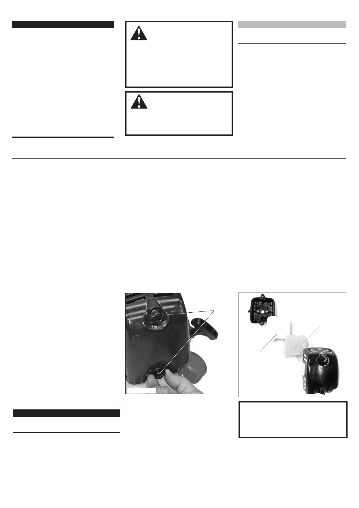
10-Hour Maintenance
Figure 12A
(more frequently in dusty conditions)
Remove the air filter cover by loosening the
two thumbscrews. See Figure 12A.
Remove and inspect the pre-filter. If the pre-
filter is torn or otherwise damaged, replace
it with a new one. See Figure 12B.
Clean the pre-filter with soap and water. Let
dry before reinstalling.
Inspect the air filter element. If the element
is damaged or distorted, replace it with a
new one.
Tap filter gently on a hard surface to
dislodge debris from element or use com-
pressed air from the inside to blow debris
out and away from the air filter element.
IMPORTANT!
Direct the air stream at the inside face of
the lter only!
1.
2.
3.
4.
5.
CAUTION!
Never operate the unit if the air lter
assembly is damaged or missing!
Install the filter element, pre-filter and
cover in the reverse order of removal.
6.
Figure 12B
Filter
Element
Loosen
fasteners
Pre-lter
IMPORTANT!
MAINTENANCE, REPLACEMENT OR
REPAIR OF EMISSION CONTROL
DEVICES AND SYSTEMS MAY BE
PERFORMED BY ANY REPAIR
ESTABLISHMENT OR INDIVIDUAL;
HOWEVER, WARRANTY REPAIRS
MUST BE PERFORMED BY A DEALER
OR SERVICE CENTER AUTHORIZED
BY SWISHER. THE USE OF PARTS
THAT ARE NOT EQUIVALENT IN
PERFORMANCE AND DURABILITY TO
AUTHORIZED PARTS MAY IMPAIR THE
EFFECTIVENESS OF THE EMISSION
CONTROL SYSTEM AND MAY HAVE
A BEARING ON THE OUTCOME OF A
WARRANTY CLAIM.
General Maintenance
Mufer
This unit must never be operated with a
faulty or missing spark arrester or muf-
fler. Make sure the muffler is well secured
and in good condition. A worn or damaged
muffler is a fire hazard and may also cause
hearing loss.
Spark Plug
Keep the spark plug and wire connections
tight and clean.
Fasteners
Make sure nuts, bolts, and screws (except
carburetor adjusting screws) are tight.
NOTE:
Using non-standard replacement parts could
invalidate your Swisher warranty.
WARNING!
Before performing any maintenance, re-
pair or cleaning work on the unit, make
sure the engine and cutting attachment
are completely stopped. Disconnect the
spark plug wire before performing ser-
vice or maintenance work.
WARNING!
Non-standard parts may not operate
properly with your unit and may cause
damage and lead to personal injury.
The E4 engine that powers your Swisher mod-
el is a hybrid 4-stroke engine. As a hybrid,
the engine is lubricated by oil mixed with
the gasoline and air from the carburetor that
moves through and around the internal parts
of the engine in a similar way that a 2-stroke
engine is lubricated. Without the heavy duty
2-stage air filter equipped on all E4 engines,
dust and dirt could also move through the en-
gine, decreasing engine life, increasing valve
wear and the need for more frequent valve ad-
justments. To keep your E4 engine strong and
reliable, Swisher recommends that you check
and service the air filter as instructed in the
10-Hour Maintenance section that follows.
Air Filter