Swiss Timing TRACKER User manual
3442.500.02
Version 2.1
Edition January 2015
User’s Manual
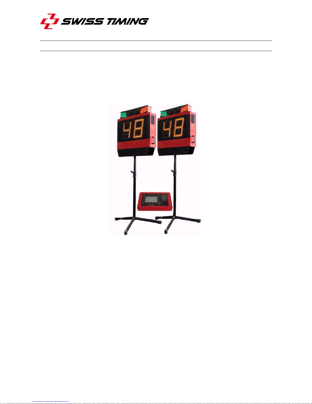
TRACKER

CAUTION
Never use any other charger than the supplied or a type approved by Swiss
Timing. This could destroy the battery, cause damage to unit, and possible
cause personal injury due to fire or/and electrical shock.
Protect the equipment against splashing, rain and excessive sun rays.
Never use the device if it is damaged or insecure.
This program may be modified at any time without prior notification.
If the case must be opened, you must call for some qualified personnel. The
power supply cable must be disconnected before opening the case.
The information contained within this document may be modified without
warning.
Swiss Timing LTD cannot be held responsible for errors within this document
nor for any subsequent nor consequential damages (including loss of profit)
arising from its provision, nor performance or use of products described
herein, which will be covered by another guarantee, contract or other legal
document.
During the transport of all Swiss Timing equipment delivered with a reusable
carry case, the said case should be used at all times. This is imperative to
limit the damage, such as shocks or vibration that can be caused to the units
during transport.
The same cases should also be used when returning equipment to Swiss
Timing for repair. Swiss Timing reserves the right to refuse all guarantees if
this condition is not fulfilled.
This symbol indicates that this product should not be disposed
with household waste. It has to be returned to a local authorized
collection system. By following this procedure you will contribute
to the protection of the environment and human health. The
recycling of the materials will help to conserve natural resources
(valid in the EU member states and in any countries with
corresponding legislation).

© Reproduction in any manner whatsoever without the written permission of Swiss Timing Ltd. is strictly forbidden.
© La reproduction de ce document, sous quelque forme que ce soit, et sans l’autorisation écrite de Swiss Timing Ltd., est strictement interdite.
© Die Vervielfältigung oder Wiedergabe in jeglicher Weise ist ohne schriftliche Genehmigung von Swiss Timing Ltd. strengstens untersagt.
P.O. Box 138, rue de l'Envers 1 Phone +41 32 488 36 11
2606 Corgémont www.swisstiming.com
Switzerland info@swisstiming.com
SWISS TIMING LTD
TABLE OF CONTENTS
1INTRODUCTION..................................................................................... 1
2INSTALLATION ...................................................................................... 2
2.1 Mobile cabling.........................................................................................................2
2.2 Fix cabling ..............................................................................................................3
2.3 TRACKER DIL switch.............................................................................................4
2.4 Power on ................................................................................................................5
2.5 TRACKER display ..................................................................................................5
2.6 TRACKER keyboard...............................................................................................5
3SOFTWARE............................................................................................ 6
3.1 Main menu..............................................................................................................6
3.2 Sport setting............................................................................................................7
3.3 Race mode .............................................................................................................8
3.4 Time........................................................................................................................9
3.5 Console setting.....................................................................................................10
3.5.1 Default parameters ....................................................................................10
3.5.2 Update the software.................................................................................11
4OPTIONS.............................................................................................. 12
4.1 Starting gate .........................................................................................................12
4.2 External Bang button............................................................................................12
5PROPERTIES ....................................................................................... 13
5.1 TRACKER connections ........................................................................................13
5.2 Main Judge Controller connections.......................................................................14
6MAINTENANCE AND PROTECTION ................................................... 15
6.1 TRACKER ............................................................................................................15


TRACKER
3442.500.02 Version 2.1 Page 1
1 INTRODUCTION
The TRACKER system is used to manage the start of pursuit races in track cycling events.
It consists of two TRACKER boards and a main judge console. It displays the countdown
and generates some sounds during the countdown. At the end of the countdown, it opens
the optional starting gates and gives the start impulse to the main timing system. After the
start, the TRACKER is used as lap counter and can indicate the leader with green and red
semaphores.
Page 2 Version 2.1 3442.500.02
2 INSTALLATION
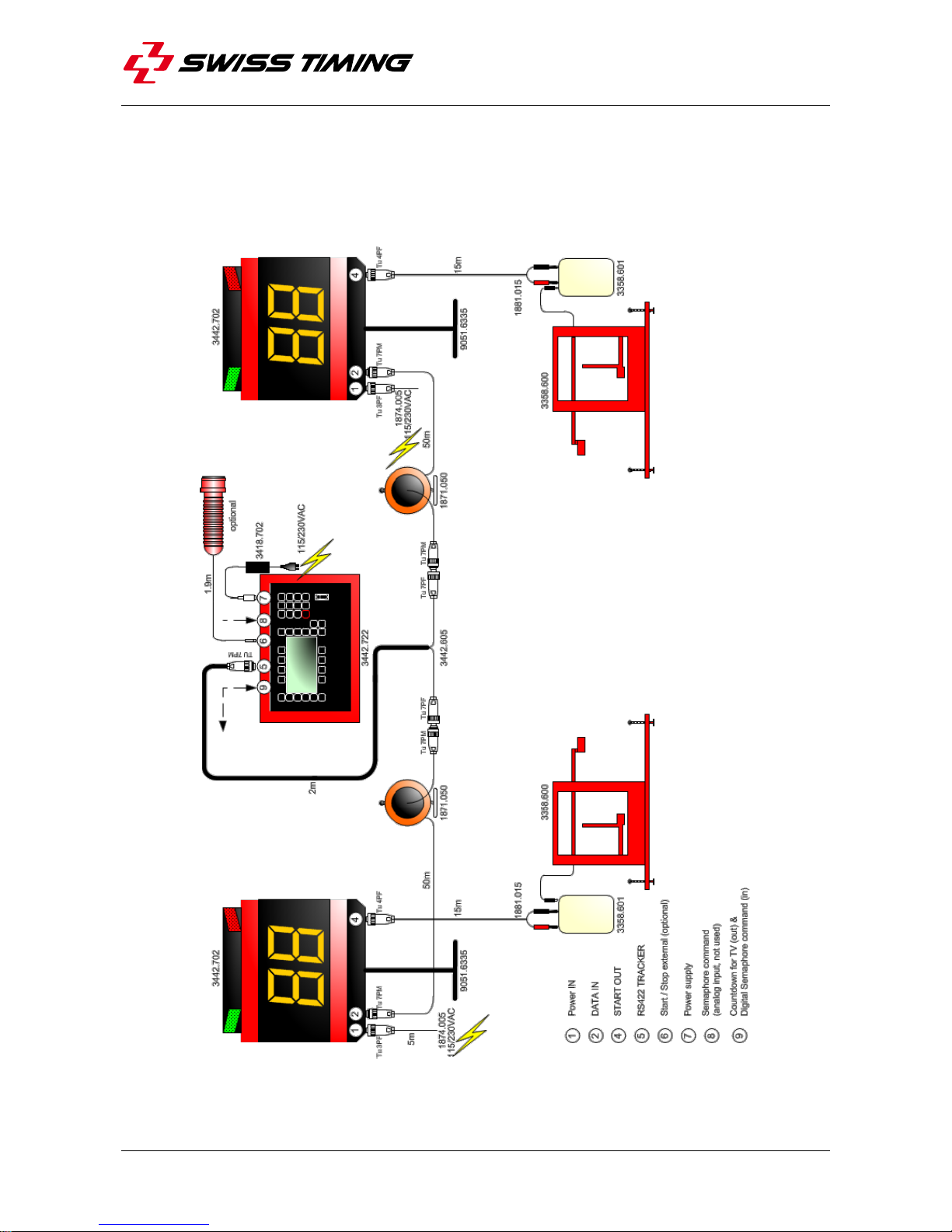
2.1 Mobile cabling
Please refer to document 3442.503 Tracker cabling (Quantum compatible).
The starting gates (3358.600 & 3358.601) are not included in the TRACKER system
(option).
TRACKER
3442.500.02 Version 2.1 Page 3
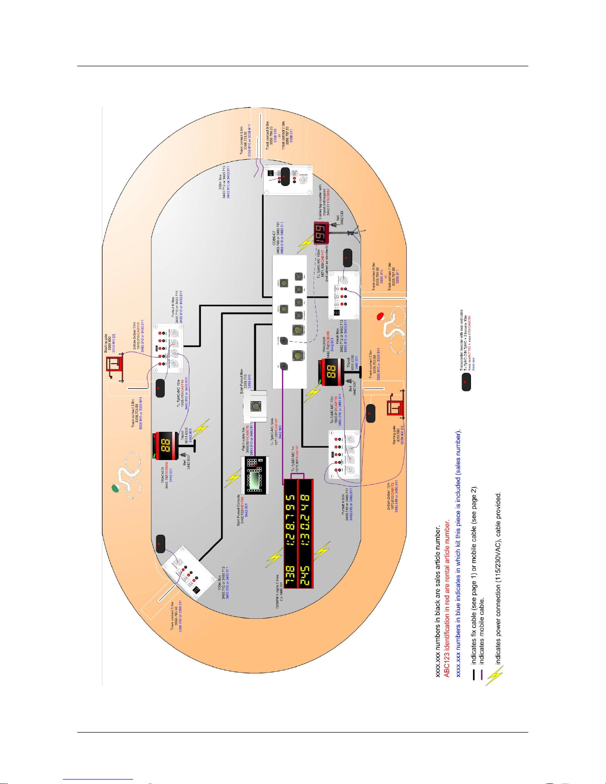
2.2 Fix cabling
Please refer to document 3493.504 (Track cycling fix cabling).
Page 4 Version 2.1 3442.500.02
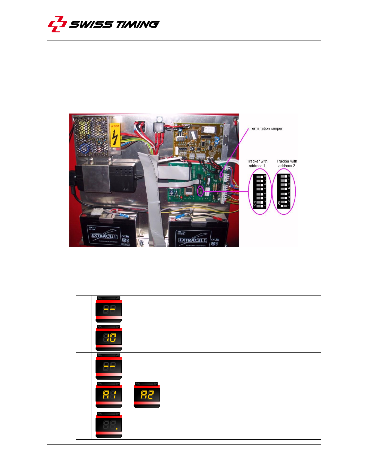
2.3 TRACKER DIL switch
Each TRACKER must have its own unique address: one must have the address 1, the
other the address 2. To select the TRACKER address, proceed as follows:
Switch off the TRACKER and unplug the power cable.
Open the rear of the TRACKER with the provided key.
Select the TRACKER address with the DIL switch (use a small screwdriver to move
them):
On some specific cabling (long cables), a termination load may be requested to
ensure correct data transmission between the main judge controller and the
TRACKER; in this case, place a jumper on the pins designated in the above picture.
Close the TRACKER.
Connect the power cable and switch on the TRACKER; during boot, the TRACKER
shows a sequence:
1.
2.
Internal software version.
3.
4.
or
Address of the tracker (1 or 2)
5.
Tracker ready to be detected and controlled by
the main judge controller.
TRACKER
3442.500.02 Version 2.1 Page 5
2.4 Power on
You must switch on both TRACKERS before switching on the main judge controller.
Turn the volume control and switch to choose the volume of the sounds (beep). Please
refer to chapter 5.1 to see where these switches are located.
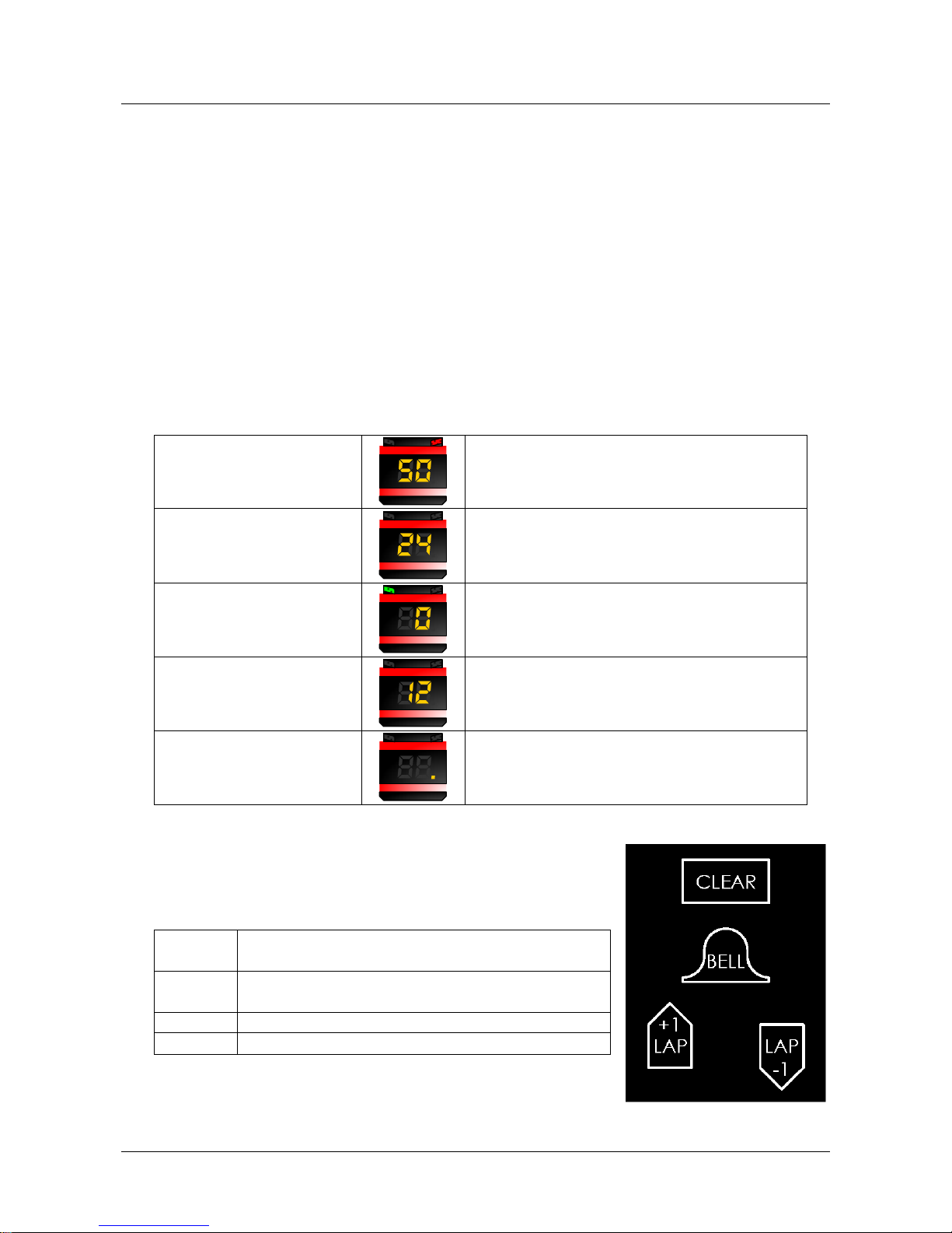
2.5 TRACKER display
When the Tracker is switched on, the right digit must display something or the point (at the
bottom right of the right digit) must be lit; this way you always know the Tracker is powered
(by main power supply or internal battery). If the Tracker’s switch is on the “I” (ON position)
and no LED is switched on on the Tracker’s front face, it indicates that the main power is
not connected and the internal battery is discharged.
Count down running
(Start/Stop switch on start position)
The red semaphore is ON
Count down stopped
(Start/Stop switch on stop position)
The red semaphore is OFF
Count down reaches 0
The green semaphore is ON
Lap counter displayed
Semaphores depend on the external
command
Lap counter cleared
Semaphores depend on the external
command
2.6 TRACKER keyboard
The TRACKER keyboard can only be used when the main
judge controller is in lap counter mode.
CLEAR
Clear the TRACKER display as long as the
key is pressed.
BELL
Play the Bell sound as long as the key is
pressed.
LAP +1
Increase the remaining lap counter.
LAP -1
Decrease the remaining lap counter.
Page 6 Version 2.1 3442.500.02
3 SOFTWARE
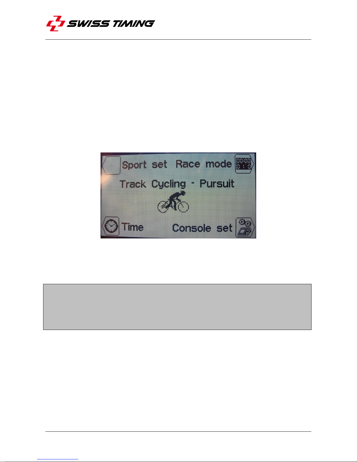
3.1 Main menu
After the TRACKER have been connected and switched on, switch on the main judge
controller with the switch on the rear side.
If the messages “Tracker 1 missing” and/or “Tracker 2 missing” are displayed, verify the
cabling and make sure the Tracker are powered and switched on; then you need to restart
the main judge controller by switching it off and on again.
After a few seconds the main menu screen should appear:
From this screen, you can go, by pressing the corresponding key, to:
Sport set(ting), see chapter 3.2.
Race mode, see chapter 3.3.
Time (& date) selection, see chapter 3.4.
Console set(ting), see chapter 3.5.
In this software, when you need to enter or modify a number, you have two possibilities:
by using the “up arrow” key to increase the value and the “down arrow” key to
decrease the value, or
by typing the number with the numeric keypad.
With both solutions, you then need to press the “Enter” key to validate the entry or the
“ESC” key to cancel your modification and return to the previous value.
Table of contents


