4. Front Panel Connections & Control Knobs/Switches
The USB Studio D Mk. II has a multitude of audio connections and controls on the front
panel. Please read the following information to understand these connections.
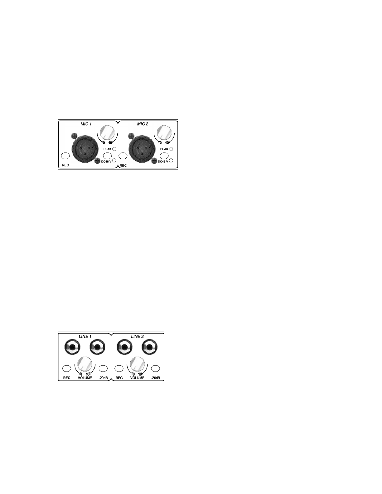
4.1 XLR Microphone Input Controls (2 x)
Independent (2 x) rotary gain controls, switchable Phantom power, peak lights, and a
record/monitor enable switch.
This is where you can connect up to two microphones, control their input gain, and choose
either to monitor the signal directly to your main outputs for monitoring, or to send the source
to the REC outputs and subsequently to your computer via USB.
Connect a microphone using a standard XLR type microphone cable and turn up the volume
knob to an acceptable level. If your microphone is a condenser microphone that requires
phantom power, depress the DC48V switch to enable power to your mic.
The REC switch directs the microphone source signal to the USB interface and allows you to
record the signal with your computer when in the drepessed position. In that case, the signal
also will be sent to the REC output on the rear panel. When in the non-depressed position the
signal is routed to the main outputs on the rear panel for live input monitoring.
The peak light illuminates to indicate when the mic pre-amp is over-driven with excessive
input signal. If illuminated, reduce the volume to avoid distortion of your microphone signal.
4.2 Stereo Line Input Controls (2 x)
Independent (2 x) rotary volume controls, -20dB pad, and a record/monitor enable switch.
This is where you can connect up to two stereo (L&R) line level devices (keyboards, sound
modules, etc.), control their input gain, and choose either to monitor the signal directly to
your main outputs for monitoring, or to send the source to the REC outputs and subsequently
to your computer via USB.
Connect your stereo (L&R) line level device with a standard 1/4” audio cables and turn up the
volume knob to an acceptable level.
9