SwitchDoc Labs SolarMax Lead Acid User manual

SolarMax Lead Acid Assembly and Testing Guide
December 2019
Version 1.4
For powering solar systems such as systems based on the
Raspberry Pi, Arduino and ESP32/ESP8266
and the SwitchDoc Labs System
Version 1.4 December 2019

Table of Contents
Errata 1.............................................................................................................................
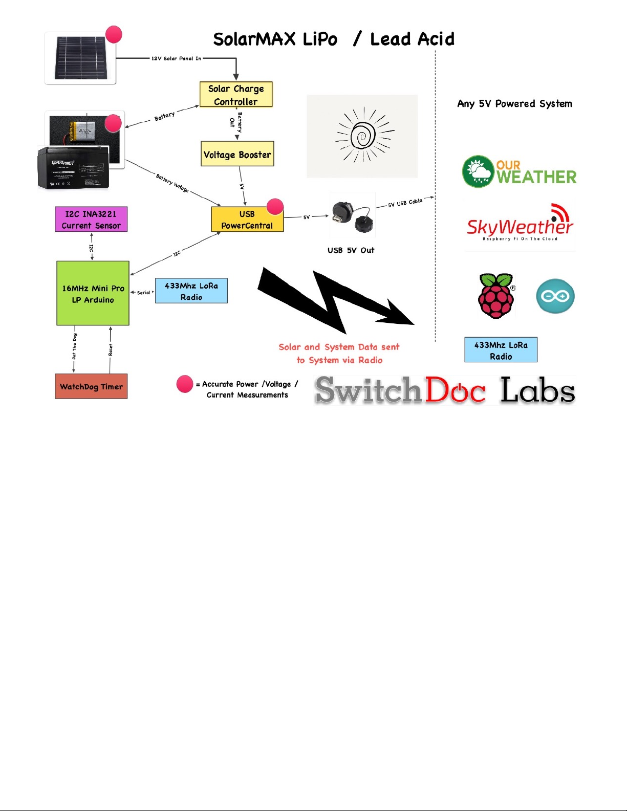
What is SolarMAX Lead Acid? 2........................................................................................
SolarMAX Specifications 3...............................................................................................
What is in the SolarMax Lead Acid Kit? 4.........................................................................
What Else is Required for the SolarMax Lead Acid Kit? 4.................................................
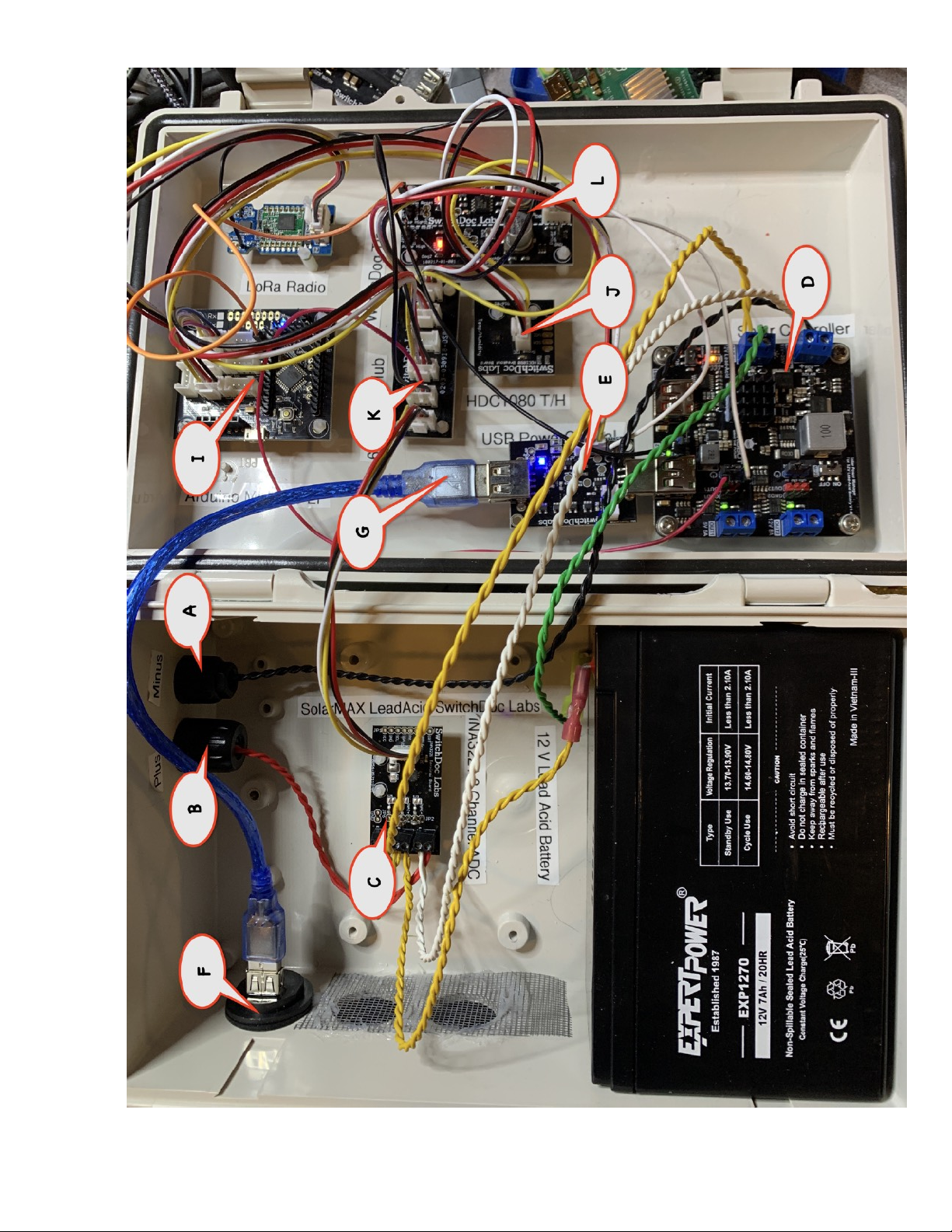
SolarMax Lead Part Identification 6.................................................................................
Step by Step Assembly 8...................................................................................................
Wiring the SolarMax Lead Acid 13....................................................................................
Solar Panel Wiring 13.................................................................................................................
Grove Wiring Table 16................................................................................................................
Jumper Wiring 21......................................................................................................................
USB Cable Wiring 23..................................................................................................................
Lead Acid Battery Wiring 24......................................................................................................
Connect your 12 V Lead Acid Battery 27.....................................................................................
Finally 29...................................................................................................................................
Testing Your SolarMAX Lead Acid System 30...................................................................
Testing With SkyWeather 30......................................................................................................
Testing with a Raspberry Pi (without SkyWeather) 31................................................................
Installing Your SolarMAX Lead Acid System 32................................................................
The Science and Education Goals Behind SolarMax 33.....................................................
Support 33........................................................................................................................
Disclaimer 34...................................................................................................................
Version 1.4 December 2019

Errata
Version 1.3 - Removed single jumper pin from LIPOBATIN to 5V. Added Grove cable from Arduino Mini Pro
LP to USB PowerCentral Enable/Control port to implement hysteresis during low power conditions. See
article on www.switchdoc.com
Version 1.4 - Removed step W8 - Not needed
Page 1
Version 1.4 December 2019

What is SolarMAX Lead Acid?
SolarMAX Lead Acid is a SwitchDoc Labs designed system to charge Lead Acid batteries from 18V Solar
panels in order to provide more power to small computer systems. SolarMAX is designed to collect and return
data about the solar panel system to the powered (or other) computer via a LoRa link. SolarMAX collects and
transmits the following data every 30 seconds:
• Battery Voltage
• Battery Current
• Solar Panel Voltage
• Solar Panel Current
• Load Voltage
• Load Current
It also supplies the following about inside the SolarMAX box:
• Inbox Temperature
• Inbox Humidity
Page 2
Version 1.4 December 2019

SolarMAX uses a 433MHz LoRa module which can transmit up to 2 kilometers or further with larger antennas
and uses very little power.
This is a perfect system for powering SkyWeather and other small computer systems.
SolarMAX Specifications
Page 3
Version 1.4 December 2019
Table 1-1
Solar Max
LeadAcid
Solar Max
LeadAcid
Minimum
Nominal
Maximum
Solar Panel
Voltage
15V
18V
18V
Solar Panel Voltage
Solar Panel VOC
25V
Solar Panel VOC
5V Load Current
5A
5V Load Current
Solar Charging
Current
4A
Solar Charging
Current
Battery Type
12V Lead Acid
Battery Type
Size of Battery
Large
Size of Battery
Cost of Battery
Low
Cost of Battery
Available Output
Voltages
5V, 12V
Available Output
Voltages

What is in the SolarMax Lead Acid Kit?
• High Current INA3221 with Terminals
• Solar Charger for 12V Lead Acid Batteries
• USB PowerCentral
• Dual WatchDog Timer
• 16MHz Mini Pro LP
• 6 Port I2C Hub
• HDC1080 Temp Hum
• LoRa 433MHz Radio
• LoRa 433MHz Radio
• MC4 Plus Female (and Pin)
• MC4 Minus Male (and Pin)
• USB Weatherproof Plug
• Short USB Cable Type A - Type A
• 20cm Grove Cables - 7 Cables
• Grove Connector to Female Pin Headers - 1 Cable
• Single Wire Female to Female Jumper - 2 Wires
What Else is Required for the SolarMax Lead Acid Kit?
12 V Lead Acid battery - We recommend >= 20000mAh - https://amzn.to/2qGCVd8 (This battery fits
PERFECTLY in the Bud Enclosure below)
M2 Nylon Hex Thread Assortment - https://shop.switchdoc.com/products/140pcs-box-m2-nylon-hex-
thread-assortment-kit
Solid Core Hookup Wire 22 Gauge - https://amzn.to/3202Ppa
Bud Enclosure NBB-22241 Style B - 6-25/32” x 10-23/32” x 6-25/32” - https://amzn.to/2zk8B8R
Spade Quick Connect Crimp Cold-Pressed Terminals (for 12V Battery) - https://amzn.to/2OgxqLm
You can buy all the above from SwitchDoc Labs as the SolarMAX Weather Proofing Kit.
100W 12V Solar Panel with MC4 Connectors - https://amzn.to/2rjjmYi (VOC 21.6V Max Power 17.4V)
Optional
Page 4
Version 1.4 December 2019

SolarMax Lead Part Identification
•Part A - MC4 Minus Male (and Pin)
• Part B -MC4 Plus Female (and Pin)
• Part C -High Current INA3221 with Terminals
• Part D -Solar Charger for 12V Lead Acid Batteries
• Part E - USB PowerCentral
• Part F - USB Weatherproof Plug
• Part G - Short USB Cable Type A - Type A
• Part H - Identical LoRa 433MHz Radio (one for SolarMax)
• Part H - Identical LoRa 433MHz Radio (one for receiving Computer)
• Part I - 16MHz Mini Pro LP
• Part J - HDC1080 Temp Hum
• Part K - 6 Port I2C Hub
• Part L - Dual WatchDog Timer
Cables
• 20cm Grove Cables - 6 Cables
• Grove Connector to Female Pin Headers - 1 Cable
• Single Wire Female to Female Jumper - 2 Wires
Page 6
Version 1.4 December 2019

Page 7
Version 1.4 December 2019

Note: Part C (High Current INA3221) will look like the picture below:
Step by Step Assembly
Step 1) Drill two 2/3” holes in the upper left side of the lower part of the Bud Box. (See Part A and Part B
location on pictures above)
Step 2) Drill 3 1” holes in the front of the lower part of the box. Separate the holes by at least 2 inches, center
to center. (Two vent holes and one hole for the Part F- USB Weatherproof Plug.
Page 8
Version 1.4 December 2019

Step 3) Insert Part F - USB Weatherproof Plug into the BUD Box, with the cap on the outside in the rightmost
1” hole. Screw down.
Page 9
Version 1.4 December 2019

Step 4) Place the large heat sink on the back of Part D, the Solar Controller. Place the smaller heat sink on the
top of Part D, the Solar Controller. If the heat sinks don’t want to stay on, us a small amount of superglue under
the heat sinks.
Page 10
Version 1.4 December 2019

Step 5) Set the slide switch on the Solar Charger (Part D) to MPPT for the most efficient charging. Then set
the Battery Gauge slide switch to Off also on the Solar Charger (Part D).
Step 6) Attach Nylon Headers (with screws or nuts) to all the boards (Parts C, D, H, I, J, K and L). Note: Part
E (USB PowerCentral) will hang off the Solar Control by itself without supports. Feel free to add them if you
wish! Note that the Solar Charger has screws and headers included in the package with the heatsink.
Step 7) Glue an additional nylon spacer on Part J (HDC1080 Temp/Humidity Sensor) and two on Part C
(INA3221) the same height of the spacers from Step 5) to provide a stable base.
Step 8) Removed
Step 9) Removed
Page 11
Version 1.4 December 2019

Step 10) Using the super glue, attach all the boards to the locations shown in the two two part identification
pictures above. Let dry. The plug in the USB PowerCentral board (Part E) into the Solar Charger Board (Part
D). Note you won’t have the battery in the box yet. But it’s OK if you do.
Step 11) Label all parts - optional - but you will be happy you did.
Step 12) Using some Silicon Caulking, attach some door screen over the center and left 1” hole to keep the
bugs out of the box.
Now we move on to the wiring of the SolarMAX Lead Acid.
Page 12
Version 1.4 December 2019

Wiring the SolarMax Lead Acid
As you wire this unit, remember you are dealing with lots of current and voltages. Triple check your wiring!
Wiring things backwards or incorrectly can result in destruction of the electronics and possible over heating.
BE CAREFUL!
Solar Panel Wiring
Step 1) Take the male Part A - MC4 Minus Male (and Pin) and two 33cm lengths of black wire. Strip the ends,
twist them together (here’s a fast way of doing that - https://www.switchdoc.com/2015/07/handy-tip-building-
braided-cables-for-projects/ ). NOTE: We have now determined that if you are using 22 AWG wire you
do not need to to double the wires. One wire is sufficient for all the currents used inside the box.
Now insert one end of the braided wire (with then ends stripped of the insulation) into the pin (the male pin has
the larger hole in the end) and crimp it down. We recommend you buy the crimper tool for MC4 plugs as
mentioned above. Slide the Male MC5 Plug into the Minus Hole in the box and put on the other parts and
screw it down.
Page 13
Version 1.4 December 2019

Step 2) Place the other end of the black wire into the “-“ terminal of the Solar Charger SOLAR IN terminal.
Page 14
Version 1.4 December 2019

Step 3) Using red 10cm long wires, braid them together, strip, crimp then and assemble the female MC4 and
install it in the Plus Hole in the box. Run the end of this wire to the 3 Channel INA3221 ADC (Part C) and
secure them in the IN2+ screw terminal.
Page 15
Version 1.4 December 2019

Step 4) Using Red 38cm long wires (We used White in the pictures above), braid them together and strip the
ends. Run this wire from the 3 Channel INA3221 ADC (Part C) IN2- screw terminal to the “+ terminal on the
Solar Charger (Part D) in the SOLAR IN block.
This completes the Solar Panel Wiring. CHECK YOUR WORK! You will destroy the electronics if you mess
up with this wiring.
Now we move on the Grove Wiring table.
Grove Wiring Table
Note - again, make sure you are connecting things to the right places. It all matters. Optional: We find the
plastic clips on the Grove cable plugs annoying and often cut them off with wire clippers.
Page 16
Version 1.4 December 2019

Select the proper grove cables and connect them as shown in the table.
SolarMAX Lead Acid Grove Wiring Table
Step #
Cable Type
From
To
Notes
Step W1
20cm Grove
Grove
Connector on
INA3221 Part
C
Any Port
on the 6
Port I2C
Hub (Part
K)
Step W2
20cm Grove
Grove
Connector
Marked I2C on
USB
PowerCentral
(Part E)
Any Port
on the 6
Port I2C
Hub (Part
K)
Step W3
20cm Grove
Grove
Connector on
HDC1080
Temp/
Humidity (Part
J)
Any Port
on the 6
Port I2C
Hub (Part
K)
Step W4
20cm Grove
Grove
Connector
Marked Grove
I2C on Mini
Pro LP (Part I)
Any Port
on the 6
Port I2C
Hub (Part
K)
Step W5
20cm Grove
Grove
Connector
Marked D6/D7
on Mini Pro LP
(Part I)
Grove
Connector
on LoRa
TX (Part
H)
SolarMAX Lead Acid Grove Wiring Table
Step #
Page 17
Version 1.4 December 2019

Step W6
20cm Grove
Grove
Connector
Marked D8/D9
on Mini Pro LP
(Part I)
Grove
Connector
on
WatchDog
Timer
(Part L)
Step W7
20cm Grove
With Female
Headers
Any Port on
the 6 Port I2C
Hub (Part K)
Red Wire
to OUT1
Pin (red
header) -
Black Wire
to GND1
(black
header
LABLED
ON1 - See
picture
below) on
Solar
Charger
(Part D)
Clip the
Yellow and
White wires
near the
Grove Plug
Step W8
Removed
Step W9
20cm Grove
Grove
Connector
Marked D3/D4
on Mini Pro LP
(Part I)
USB
PowerCent
ral
Control/
Enable
Grove
Connector
SolarMAX Lead Acid Grove Wiring Table
Cable Type
From
To
Notes
SolarMAX Lead Acid Grove Wiring Table
Step #
Page 18
Version 1.4 December 2019
Table of contents