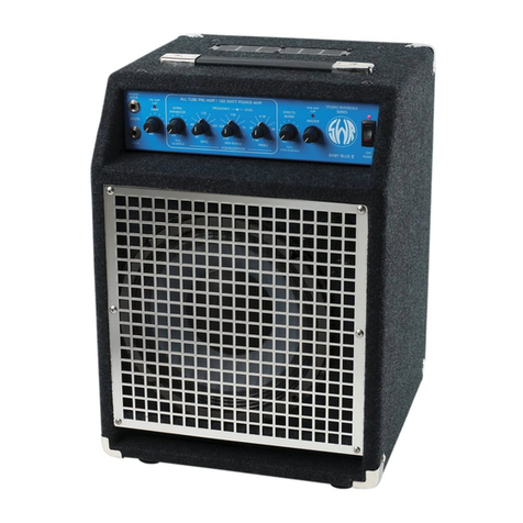
SWR Baby Blue Head User manual

Baby Blue Head
GENERAL DESCRIPTION AND DATA
The Baby Blue (head only) was designed and developed for the discerning professional bass player in need of a superior
small bass head for studio and small venues.
The precision electronic section is entirely hand-built and employs everything from vacuum tubes for the preamp section to
discreet solid state components for the power amplifier. Each individual component was selected for reliability and accurate
reproduction of the signals from both electric and acoustic instruments. The features were selected with an emphasis on
studio applications and for use in live settings where a very true signal is needed. By using just the power switch and
volume controls, we believe you will experience the cleanest and most transparent sound you have heard out of your
instrument. The Aural Enhancer and Tone sections are designed to bring out the "character" of the individual musician and
their instrument without altering or masking their inherent qualities and/or techniques.
We truly hope that this "instrument" helps bring out the best in your playing and adds to the enjoyment of your profession.
We would like to sincerely thank all the musicians and engineers that helped us with this project and especially Walter
Becker, Neil Stubenhaus, Phil Chen, Keith Jones, Jimmy Haslip, Michael Rhodes, Phil Lesh, Dan Schwartz, Dann Glenn and
Dwayne "Smitty" Smith.
SPECIFICATIONS -ELECTRONICS
Note: All measurements were taken with a line voltage of 120VAC.
Maximum power at 1KHz under clipping: 120 Watts RMS @ 8 ohms, 160 Watts RMS @ 4 ohms
Power Amp Distortion (1KHz)
0.02% THD, 100 Watts RMS @ 8 ohms
0.03% THD, 100 Watts RMS @ 4 ohms
Intermodulation Distortion @ 8 ohms, 100 Watts RMS, 60/7KHz, 4:1, =0.05%
Frequency Response (power amp): -3db at 10 Hz and 22KHz
System Distortion
(Gain and Master Volume full, enhancer and tone controls set flat,
1KHz): 0.5% THD
Sensitivity (for full output @ 8 ohms, 1 KHz)
Passive/Active Input Jack = 10 millivolts
Active Input Jack = 50 millivolts
Input Impedance
Passive/Active Input Jack = 800K ohms
Active Input Jack = 60K ohms
Effects Return Jack = 27K ohms
Output Impedance
Effects Send Jack = 100 ohms
Line Out Jack = 100 ohms
Tuner Out Jack = 100 ohms
Headphone Jack = 100 ohms
Signal to Noise Ratio
unweighted -72db
(7 millivolts typical, mostly hum)
Equivalent Input Noise: 2.5 micro-volts
FRONT PANEL FEATURES
PASSIVE/ACTIVE
This input can and should be used if your instrument has passive electronics (no built-in preamp). Some pickups such as
EMG, etc. employ batteries for operation and will work perfectly using the Passive/Active input. Technically speaking, this
input should be used if your instrument has an output voltage of 1 volt RMS or LESS. Consult your owners manual or ask
the manufacturer if you are unsure.
NOTE: If you hear a small amount of distortion and neither the Preamp Clip LED or Power Amp clip LED are activated, try
using the Active Input Jack. Some built-in preamps such as those made by Bartolini can be used in the Passive/Active
input.
If you would like to overdrive the first TUBE stage, this can be accomplished by using a preamp between your instrument
and the Passive/Active input. To obtain optimum sound when trying this, make sure the Preamp clip LED is not activated.
If this occurs, turn down your Gain Control. The first preamp stage is NOT monitored by the Preamp clip circuit for this
reason.
ACTIVE INPUT
The Active input jack should be used with instruments having a built-in (on board) preamp that will produce signals over 1
Volt RMS. Known basses that should use the Active input only are Kubicki X-Factor and some Ovation Electrics. Some
really "hot" pickups installed in your instrument may find the Active input more compatible. The best judge is your own
ears. If you are using KEYBOARDS (such as a Roland D-50, etc.) with the Baby Blue, we have found the best input to be

the Active input.
NOTE: Using the Active input with passive basses (active instruments will always employ a battery) may result in a loss in
high end transients. Players who roll off their high end starting at about 2K to 3KHz may find this input more to their liking.
If you hear some distortion on your active bass and are using the Active input jack, CHECK YOUR BATTERY!! Also, make
sure none of the overload indicators are lit.
PREAMP CLIP LED
The preamp clip LED will become lit whenever the preamp, tone section or output buffer reach clipping (run out of
headroom). This function does NOT monitor the first tube stage of the Passive/Active input jack (see that section for more
info). In the event the preamp clip indicator lights, turn down the Gain control. Since the preamp clip LED also monitors
the tone section, boosting any one of the tone controls can cause the LED to activate. In any case, turning down the Gain
control will correct the
situation.
NOTE: Constant clipping of the preamp will not harm the electronics in your Baby Blue, however, damage can occur to
some speakers due to near-DC content present in a clipped waveform. Overdriving the first tube stage as described in the
Active/Passive input jack section, does not apply to the above note.
GAIN CONTROL
The Gain control adjusts the volume of the preamp section. After the tone controls, Aural Enhancer and any effects you
may be using have been set to your liking, the Gain control should be set to where the Preamp clip LED barely flashes
upon striking your loudest note. After that has been accomplished, use the Master Volume to set the desired volume level.
Utilizing these controls in this manner assures the user of maximum signal to noise ratio with no distortion caused by the
preamp circuits clipping. Since the Gain control is similar to a "pad," a small amount of signal will get through with the
Gain control rotated fully counter-clockwise.
AURAL ENHANCER
The Aural Enhancer was developed to bring out the fundamental low notes of the bass guitar, reduce certain frequencies
that help "mask" the fundamentals and enhance the high-end transients. This effect becomes more pronounced as the
control is turned to maximum. the result is a more transparent sound and is especially noticeable with a slap style
technique of playing.
EQ DEFEAT
By pulling out on the Aural Enhancer knob until you hear a click, you can defeat the tone control section (return to a flat
response). This feature can be very useful in studio situations ("let's hear your eq, now let's hear it without it.") or in
simply analyzing how you have set your tone controls with respect to a flat response.
TONE CONTROL SECTION
The tone control section is a semi-parametric type with both level (cut and boost) controls and frequency controls. The
INSIDE knob is the LEVEL control and the OUTSIDE knob is the center FREQUENCY control. The level control boosts or cuts
(raises or lowers) the tone set by the frequency control. If the level control is in the flat (center click) position, the
frequency control will have no affect to the sound.
To assure the user of the flat (out) position of any one tone control, a center click position has been provided. A twenty
four stepped frequency control has been provided for the user so that they may always re-find a desired tone. As you find
different settings that are desirable, you may want to make a note of them.
The easiest way to get acquainted with the semi parametric is to raise the level control close to +15, then rotate the
frequency control from one end to the other noting the change in sound. Do this with each section (bass, midrange and
treble) one at a time. Chances are that with each section you will find a couple of positions that are especially pleasing or
unpleasing to your ear. As these are found, adjust the LEVEL control to the desired amount of cut or boost that is desired.
After finding a position on each control, activate the EQ DEFEAT switch to compare. The more you do this, the more you
will relate frequency "numbers" to their respective sounds. The goal that can be reached is to be able to easily find
adjustments with the tone section that are needed. For example:
Not enough solid low end...................boost the 40-60Hz range
Midrange is honky or hollow sounding......cut the 600-1000Hz range
Treble is harsh and hurts the ear.....cut the 1.5K to 2.5KHz range
Having trouble cutting through the band.........boost around 200Hz
Not enough presence, lackluster..........boost from 5KHz to 7.5KHz
Too much pick or finger noise.........cut the 5KHz to 7.5KHz range
Need a more dynamic, "piano" sound......cut 800Hz, boost 40 & 6KHz
Want to sound like Marcus Miller....................practice a lot
We suggest you try all of the above examples. Then try doing just the opposite to realize both ends of the spectrum. Keep
in mind that the amount of cut or boost is something only you can decide.
EFFECTS BLEND
The Effects Blend control "blends" the signal coming from your instrument with the sound coming from your effect. With
the Blend control full counter-clockwise, no signal from your effect will be heard. As you turn this control clockwise, more
of the effect can be heard in the overall sound. When the Blend control is full clockwise, no true or unaffected signal is
heard other than what your effects unit provides.
This type of control and arrangement is very effective in reducing noise caused by effects units and in maintaining a more
natural sound. Please read the "Effects Loop" section for more information.
EFFECTS BYPASS SWITCH
Pulling out the Effects Blend control will bypass the signal coming from the effects unit and will return you to the sound of
your instrument only. This feature will function regardless of the position of the Effects Blend control. Always check the
position of this control if you are having trouble with your effects unit.
MASTER VOLUME
The Master Volume adjusts the signal level going to the power amplifier and HEADPHONES when they are used. It DOES
NOT control the output of the effects send jack, line out jack or line position of the XLR balanced output. If the power amp
clip LED lights more than occasionally, turn down the Master Volume to correct this condition.
POWER AMP CLIP LED
The Power Amp Clip LED will light when the internal power amp reaches clipping (runs out of headroom). Although no
harm will come to the electronics due to the power amp clipping, continual clipping of the power amp will shorten the life of
the internal (or any) speakers and could cause them to fail. SPEAKERS THAT HAVE FAILED DUE TO CONTINUOUS
CLIPPING OF THE POWER AMP WILL NOT BE COVERED UNDER WARRANTY! Occasional clipping of the power amp (no more
than every fourth or fifth note) will not harm the internal speakers. Turning down the Master Volume will correct this
situation.
POWER SWITCH
Pressing the Power Switch to the ON position activates the Baby Blue's electronics as indicated by the red LED lighting.
BACK PANEL FEATURES
BALANCED XLR OUT
The Balanced XLR Out is a true balanced output whose level is set by the XLR Pad directly to the left. The signal appearing
at the XLR jack is governed by the position of the Line/Direct switch directly below the jack. In the LINE position, all front
panel controls are functional and the signal is essentially the same that is being sent to the internal power amplifier. If you
are using an effect, this will also
appear mixed in the signal when you are in the LINE mode. In the DIRECT position, the Balanced out becomes an active
TUBE direct box. No front panel controls are functional and once again, the level is adjusted by the XLR Pad.
When using the Balanced Out for recording, optimum results can be achieved by DRIVING THE TAPE DECK DIRECT. Of
course, if this is not possible, the Baby Blue will work in any other situation. Whenever possible, use the XLR Pad to adjust
working levels. The use of input pads on consoles can deteriorate sound quality.
A ground lift is built into the XLR Pad control. To lift (remove) the ground connection, pull the knob outward until it clicks.
If a persistent hum exists after trying both positions of the ground lift function, there is probably a problem with the AC
wiring or just a dirty AC line. If this is the case, we suggest using an isolation transformer between the Baby Blue and the
wall socket.
Wiring for the XLR connector is as follows: Pin 1 = ground, Pin 2 = +, Pin 3 = -(American Standard)
XLR PAD
The XLR Pad adjusts the level (volume) appearing at the XLR connector. Volume increases as the control is turned
clockwise. The XLR Pad has a built in ground lift for the balanced out. Pulling the knob outward disconnects the ground (pin
1).
If you are in the LINE position and change the Gain control on the front panel, the level will also change at the balanced
output. You may readjust the record level if necessary with the XLR Pad without affecting any other function.
NO PHANTOM POWER (48V SUPPLY) SHOULD BE APPLIED TO THIS OUTPUT. DOING SO MAY DAMAGE THE INTERNAL
CIRCUITRY.
LINE/DIRECT SWITCH
In the Line position, the signal going to the power amp also appears at the Balanced out jack and all front panel controls
are functional. In the Direct position, a direct signal from the input jacks appears at the XLR connector. For further
information, see "Balanced XLR Out" above. When using this switch, make sure it is all the way to the left or right and not
in a "half way" position.
NOTE: Turn off transients appear at the record outs when the amplifier is turned off. It is recommended that equipment
that is being used in conjunction with the record outs be turned down, off, or disconnected BEFORE the Baby Blue is turned

off.
LINE OUT
The Line Out jack is located POST EQ and PRE Master Volume in the block diagram. This function will allow you to drive an
additional (slave) power amplifier or can be used as an unbalanced record out. Any effects used in the effects loop will
appear at the Line Out jack as well. The overall level is set by the GAIN control on the front panel.
TO TUNER INPUT
The Tuner Input jack allows the user to plug their instrument tuner into this jack and "tune up" without having to unplug
and go back and forth from amp to tuner. This feature is totally isolated from the rest of the preamp and will function
regardless of the settings of the controls on the front panel. Being on a side chain (isolated) also avoids loading down of
the instrument causing a loss in the dynamic range
of your instrument.
To use this feature, plug in a shielded patch cord from the Tuner Input to the INPUT on your tuner. Turn the amplifier on
and you're ready to go. If you do not wish to monitor your sound while tuning, you may turn the Master Volume down. If
you are in the studio and sending a feed to the "house," you may want to turn down the XLR Pad so you won't disturb the
drummer who has been trying to get his sound for the last 6 hours!
EFFECTS LOOP
The Effects Loop is located POST EQ and PRE Master Volume in the block diagram. The signal level appearing at the Send
jack is controlled by the Gain control on the front panel. If you are getting too hot a signal to the input of your effect,
reduce the level of the gain control and raise the level of your Master Volume to retain similar overall volume levels. By
using the Gain, Master Volume and Effects Blend control in conjunction with each other, optimum results should be
obtainable with any effects unit.
The Effects Loop is designed as a "side chain" (parallel) function similar to those found on studio consoles. Use of the
effects loop should greatly reduce the noise generated by effects devices (as compared to in-line effects loops). Additional
features of this type of loop can be found below under the Receive jack section.
SEND JACK
Run a shielded patch cord from the Send jack to the INPUT of your effects unit. This jack may be used as an additional line
level output.
RECEIVE JACK
Run a shielded patch cord from the RECEIVE jack to the OUTPUT of your effects unit.
One unique feature of the receive jack is the ability to practice along with pre-recorded music. Insert a tape recorder or
other sound source into the Receive jack (make sure it is a mono source). Using the Blend control, adjust the level of
recorded music from the Receive jack to the "live" sound of your instrument. The mixed sound will be heard through the
internal speakers and/or your headphones. This feature appears on our Redhead and musicians receiving audition tapes, or
practice tapes from bands they are soon to join have found this to be invaluable.
Bass players generally complain that they are not loud enough in the studio mix. To solve this problem, run a feed from
the headphone mix or console mix to the Receive jack. Using the headphone jack on the Baby Blue, adjust the Blend
control to the desired level you want to be in the mix! This can only be done if the Line/Direct switch is in the DIRECT
position and your speakers are not being miked. If you are in this position, you can also make your own private tape of the
session by inserting a cassette deck in the
Line out jack.
NOTE: Inserting a plug into the Receive jack activates the Effects Blend control. The Effects Blend control "receives" this
command through the ground created by insertion of the plug in the jack. Therefore, best results can only be obtained by
using a mono phone plug. If you have a stereo plug only, tie the ring and the ground together.
If you are not getting any "effect" through your speakers, etc., check the position of the Blend control and the Effects
Bypass switch located on the front panel.
HEADPHONE JACK
The headphone feature allows the user to monitor their sound via the use of stereo headphones. "Silent" practicing can be
achieved by removing the speaker cable from the back of the Baby Blue electronics. Do not remove the cable from the
cabinet jack only as there is a chance the cable could hit a "ground" and momentarily short out the power amp. NO HARM
will be done to your amplifier by not having any
speakers plugged in.
WARNING: Stereo headphones must be used in this jack as mono headphones will short out one side.
Since the headphone "amp" is actually a reduced signal from the power amp, the Headphone volume is controlled by the
Master Volume.
SPEAKER JACK
The Speaker jack should be used to connect the amplifier to a set of speakers. Make sure that the impedance of the

cabinet that you are plugging in is NOT LESS THAN FOUR (4) OHMS. Use a good quality speaker cable that is at least 18
gauge or heavier (the lower the gauge, the heavier the wire). DO NOT USE INSTRUMENT CABLE FOR HOOKING UP
SPEAKERS!!
EXTENSION SPEAKER JACK
The Extension Speaker jack can be used to plug in a second set of speakers. If you use this feature, make sure that the
impedance of the cabinet that you are plugging in is NOT LESS THAN FOUR (4) OHMS. Use a good quality speaker cable
that is at least 18 gauge or heavier (the lower the gauge, the heavier the wire). DO NOT USE INSTRUMENT CABLE FOR
HOOKING UP SPEAKERS!!
SPEAKER FUSE
This feature is provided to protect your speakers in the unlikely event of a power amp failure or your power amp from bad
speakers or their respective cables. This fuse can open (blow) if your amp is on and you are playing while plugging in the
internal speakers or an extension speaker cabinet. This is because the power amp is momentarily shorted out to ground.
Always check this fuse first if no sound is coming from your cabinet(s). Correct size and rating of the speaker fuse is: 3AG,
6 amp, fast blow.
A/C LINE FUSE
The line fuse can open (blow) due to power surges or high powerline transients. This fuse will also open in the event of an
electronics failure inside your amplifier.
Correct size and rating of the Line (Mains) fuse is 3AG, 3 amp slo blo for 120V operation and 1 1/2 amp slo blo for 240V
operation.
DO NOT DEFEAT THE PURPOSE OF THIS FEATURE BY USING A FUSE WITH A HIGHER RATING. IT CAN FURTHER DAMAGE
YOUR AMP AND VOID YOUR WARRANTY.
!
Table of contents
Other SWR Amplifier manuals

SWR
SWR WORKINGMAN'S 2004 User manual

SWR
SWR 350x User manual

SWR
SWR Super Redhead User manual

SWR
SWR California Blonde User manual

SWR
SWR LA 15 User manual

SWR
SWR Workingman's 8004 O User manual

SWR
SWR WorkingPro WorkingPro 12 User manual

SWR
SWR California Blonde II User manual

SWR
SWR Super Redhead User manual

SWR
SWR Mo' Bass User manual