SwyxDECT 500 System Configuration of a SwyxDECT 500 base station 5
14. Please enter in the field "Secondary Registrar-Address:" the IP-
addres of the Standby Server.
15. Activate "SIP Session Timers."
16. Enter the value "90" in the "SessionTimer Value" field.
17. In the field "DTMF signaling", select "SIP-INFO".
18. Click on "Save."
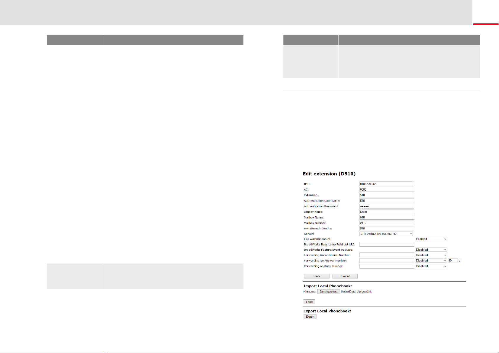
19. Add a new user.Weitere Informationen entnehmen Sie bitte dem
Abschnitt How to add a new user, Seite 8.
1.5.2 Configuration of a multi-cell system
A multi-cell system is an aligned and synchronized system of base sta-
tions, covering larger radio ranges. Up to 254 base stations can be used.
They can be set up in chains (up to 24 base stations per chain).
Before installing a multi-cell system, all requirements regarding radio
coverage, number of DECT users, their movements, as well as the instal-
lation site (building information) have to be met. Verify if any interfe-
rence factors are present that may have a negative impact on the DECT
installation.
Please adhere to the following sequence of steps to configure a multi-
cell system.
Setup first base station (step (1) to (9))
Add server (Step (10) to (18))
Add at least one user (step (19))
Set first base station to "multi-cell" (step (20))
Add second base station (repeat step (1) to (9) followed by (20) to
(22))
In order to support Codec G.729, an optional module for the base station
is required (one module per base station). The codec G.729 should be pla-
ced after codec G.711U in the priority list.
In general: You can save configuration changes by clicking on "save." If
there is no "Save" button available on the respective site, changes have to
be confirmed by restarting the base station.
How to configure a multi-cell system
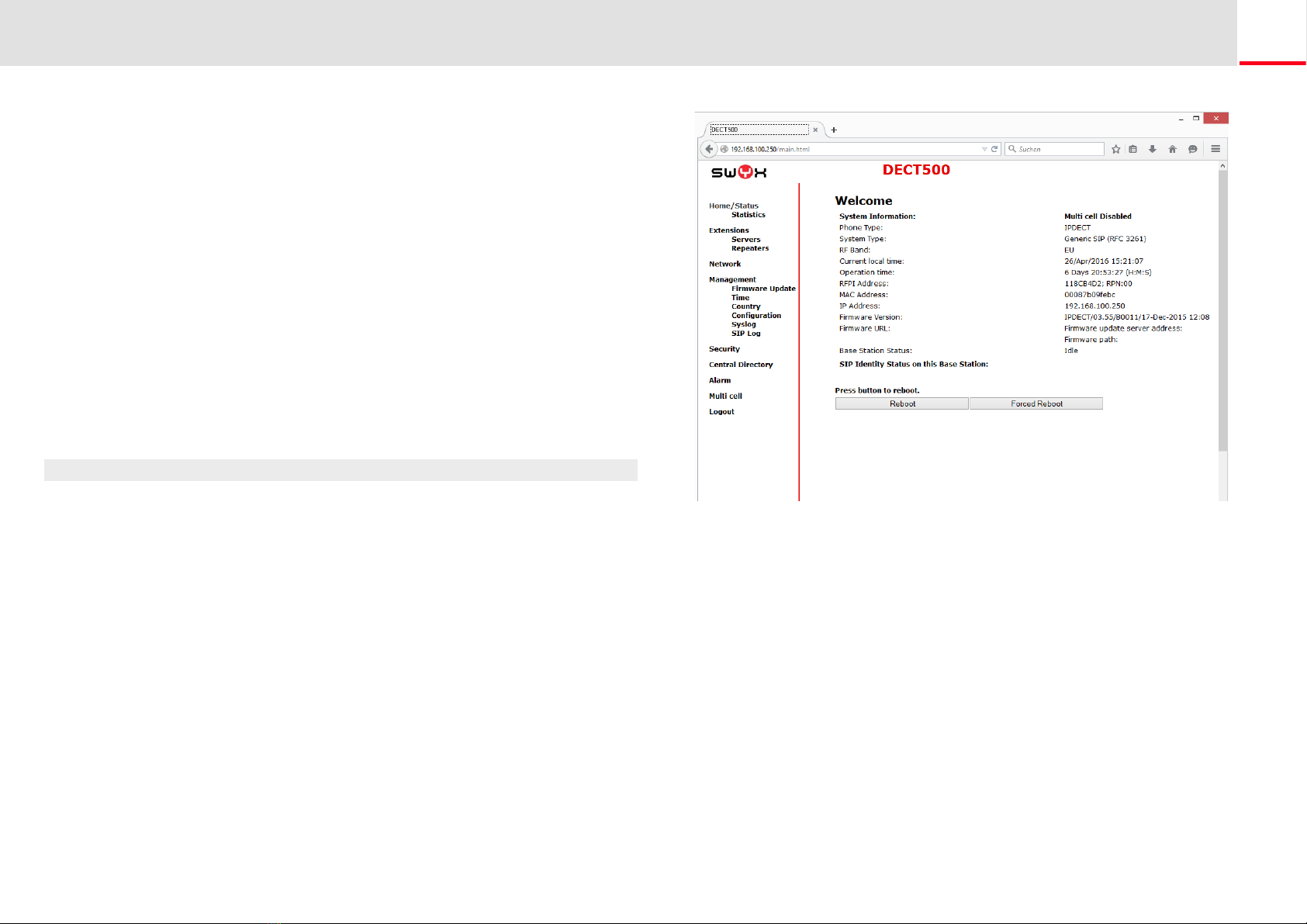
1. Enter the IP address of the base station in the address bar of a
browser.
A login window will open.
2. Enter the user name and password. By default the user name and
password is "admin" and "admin".
3. The home page of the web interface to configure the SwyxDECT 500
base station opens.
4. Go to the menu bar and click on "Management | Country setting"
and select the country and the desired language. Confirm your
selection by clicking on "Save and Reboot".
The system restarts.
5. Select the "Management | Time settings" option, and enter the IP
address of your Windows server or a public time server (e.g.
ptbtime1.ptb.de) in the field "Time Server". This synchronizes the
time being displayed on the DECT handsets.
6. Click on "Save and Reboot".
The system restarts.
7. Select the "Management" option.
8. Give the base station a name.
9. Confirm the entry by clicking on "save".
10. Select the "Extensions | Server" option.
11. Click on "Add server".
12. Deactivate the NAT adaption.
13. Enter the SwyxServer's IP address in the "Registrar" field.
14. Please enter in the field "Secondary Registrar-Address:" the IP-
addres of the Standby Server.
15. Activate "SIP Session Timers."
16. Enter the value "90" into the "Session Timer Value" field.
17. In the field "DTMF signaling", select "SIP-INFO".
18. Click on "Save."
In order to support Codec G.729, an optional module for the base station
is required (one module per base station). The codec G.729 should be pla-
ced after codec G.711U in the priority list.