sy.uk 4V1.0
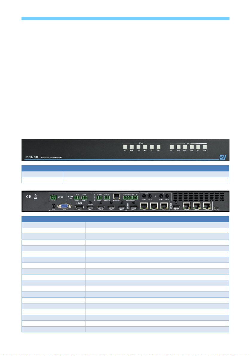
An LED can be used in parallel with each switch, mirroring the input selection status as per front
panel (FP). Any input selection (from FP, external PB switches, RS232) is accordingly reflected
on all FP LEDs, External PB switches/LEDs, and the RS232.
The output that is controlled by the external switch can be set using an RS232 command. The
available settings are: Zone 1 only; Zone 2 only or both Zone 1 and Zone 2 together.
An additional feature provided by this external keypad is that each time the DP and VG buttons
are pressed simultaneously, the controlled output Zone toggles between controlling Zone 1 only,
controlling Zone 2 only, or controlling both Zones together. The controlled output Zone setting is
indicated by all the button LEDs of the Zone lighting up briefly when the VG and DP buttons are
released.
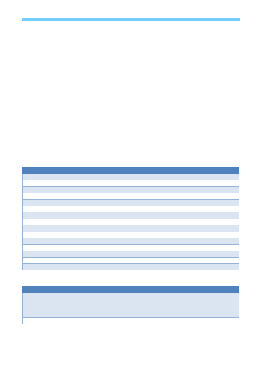
RS232-CTL Commands
All RS232 commands are sent with the following settings:
57600 baud, 8 data bits, no parity and one stop bit.
Commands are not case sensitive, but must always be followed by a carriage-return (0x0d). All
spaces are optional, but are shown in the command tables for clarification.
All response messages are in uppercase and provide an acknowledgement of the command or
reply with the requested data. All responses are terminated with a carriage-return & line-feed
sequence (0x0d 0x0a).
System Settings
Get a list of all available commands
Get a verbose list of all current system settings
Get a short list of the current system settings
Set the system address to xx
Set a new Host IP address
Get the current Host IP address (default: 192.168.1.239)
Set a new router IP address
Get the current Router IP address (default: 192.168.1.239)
Get the current network mask (default: 255.255.255.0)
Set a new TCP port number
Get the current TCP port number (default: 23)
Set the DHCP status, where x is 0 = OFF (Static IP) and 1 = ON
Get the current DHCP status
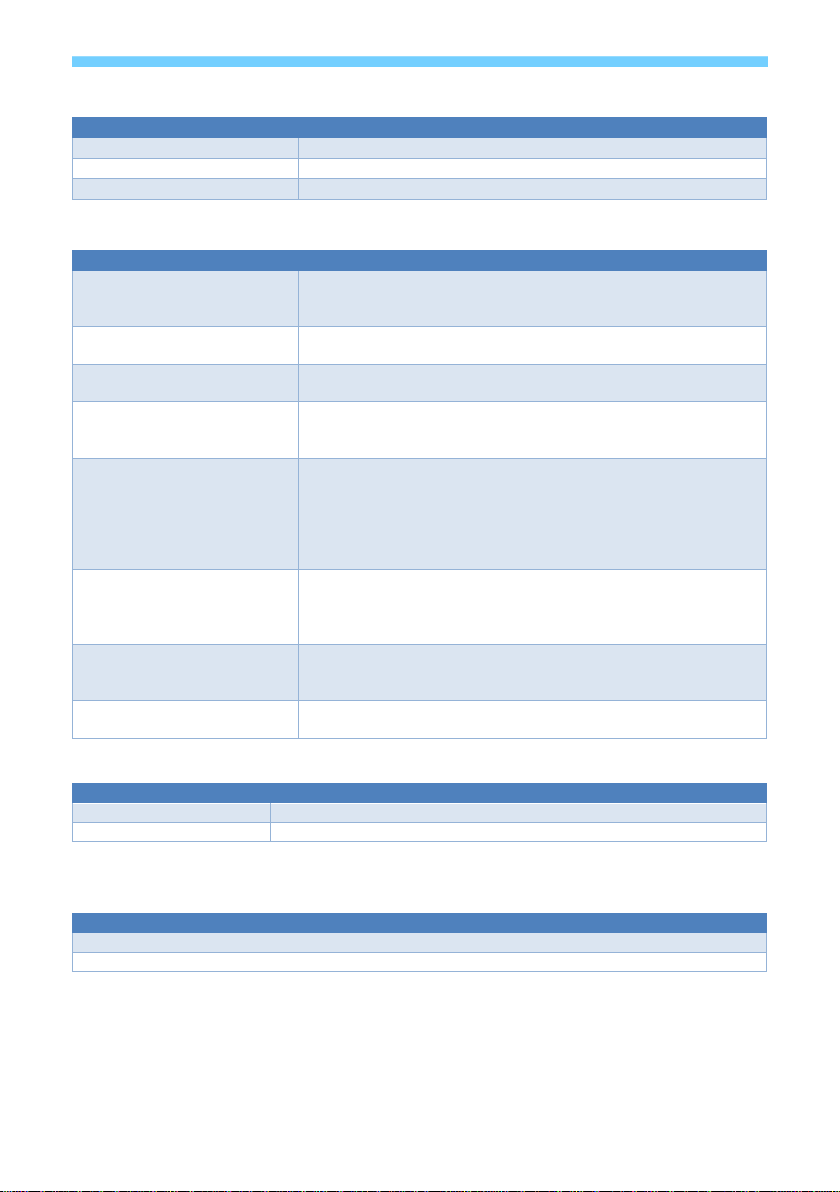
Video Settings
Set the output x to input y.
Where x is: 0 input y is selected to both output zones
1 for zone outputs, or 2 for Zone 2 outputs
Where y is: 1 – 4 (HDMI 1 – 4), 5, (DisplayPort), or 6 (VGA)
Get the currently selected input for output zone x (1 or 2)