98
8
24. TAPE INPUT
It is allowed the tape recorder.
7
19. " PRIORITY" TERMINAL
When short-circuiting these terminals (i. e. by means of using an electrical switch). The audio
signals coming from "AUX IN" are muted.
20. "INPUT 2" AND "INPUT 3" INPUTS SENSITIVITY AND XLR PHANTOM 48V SWITCH
INPUT VOLUME CONTROL
By turning these switch onto the "LINE" position the"IN2", "In3" input can be connected
to an audio source with high level signal output. By turning these switches onto the "MIC"
position the "IN2","IN3" input can be connected to a dynamic microphone with low imped-
ance. By turning these switch onto the "48V" opsition connects "the 48V" phantom supply
on XLR of pin2 and pin3 of inputs "IN2","IN3", necessary to operate condenser type micr-
ophone which require this type of external supply. It is recommended to use this switch
with the general volume set on minimum.
23. SOURCE SELECT SWITCH
Music source input select switch, this switch select the CD,AUX or TAPE.
25. CD INPUT
It is allowed the CD signal to input.
27. "INPUT 2" AND "INPUT 3" INPUTS
These three balanced/unbalanced combination type jack (XLR and 6.3mm) inputs, meant for the
connection of condenser type microphone that accepts 48V phantom power, dynamic microphone
(30- 600 ohms) or a high level sound source (e.g. AM/FM tuner, cassette desk, CD player, etc.).
In case you are using, it is necessary to use the switch (22). "Input 1" has a "Voice Priority"
function that excludes all the other inputs as soon as a message is transmitted with a
microphone.
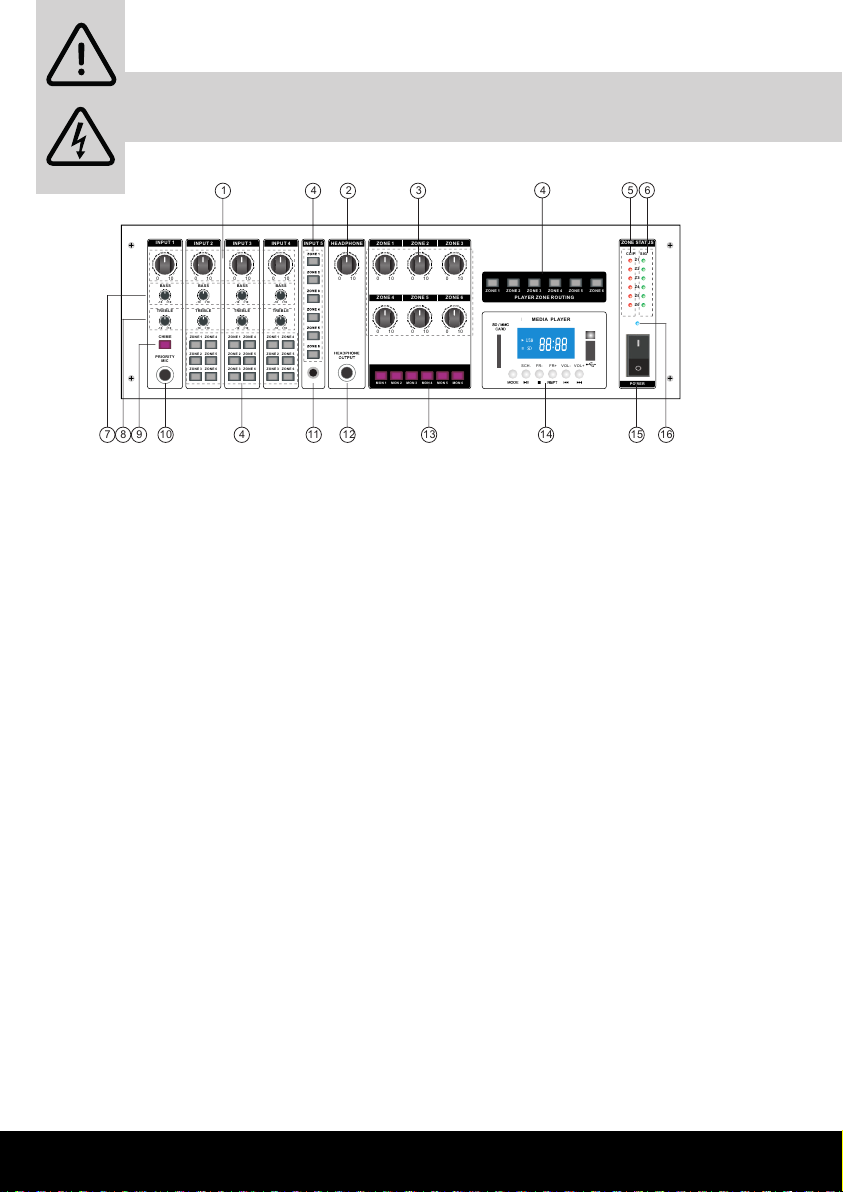
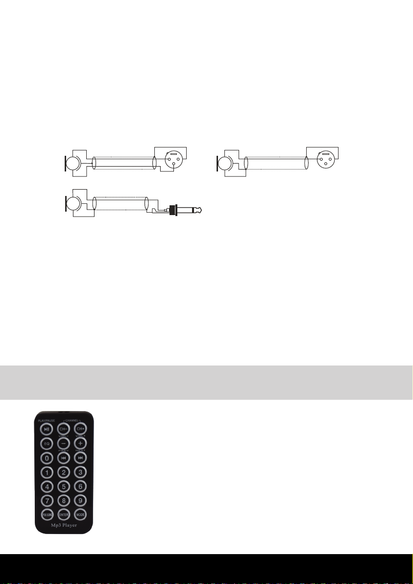
Balanced microphone 3-pin XLR plug
(seen from welded side) Unbalanced microphone 3-pin XLR plug
(seen from welded side)
Unbalanced microphone
Unbalanced signal (channel L or R)
Earth
RCA plug
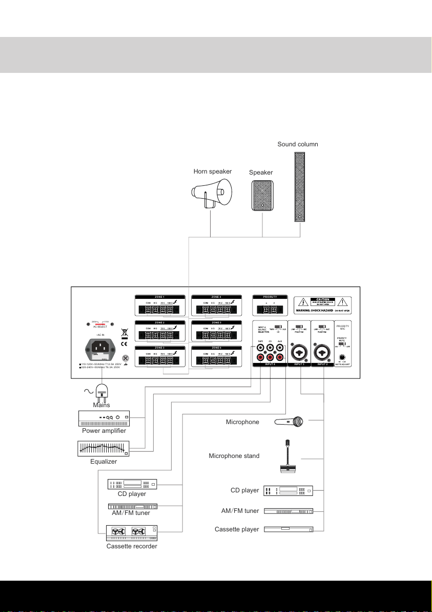
26. AUX INPUTS
The "R" and "L" sockets permit input of the right ("R")and left ("L") channels of an audio source
with a high-level output signal , such as an AM/FM tuner, a cassette deck, a CD player, etc. Use
input sensitivity switch (21),suitable for difference appliances. They are able to take RCA-type
coaxial connectors, and unbalanced signals.
Auxiliary conctat
This switch is used to select voltage (115V / 230V) as requirement.
21. VOLTAGE SWITCH
22. AC CONNECTOR AND AC FUSE
This connector is meant for the connection of the spplied mains cord, The fuse protects
the alternating currents supply circuit of the equipment. The fuse can only be changed in
the event of a fault.
28. PRIORITY CONTROL
This knob can control the signals that be muted output level.
29. PRIORITY MUTE
The ability of input 1 to mute the other inputs can be enabled or disabled using this switch.
TECHNICAL SPECIFICATION
OUTPUT POWER CAPACITY
RMS: 6*100W
AC: 115V/ 230V 60Hz / 50Hz select abl e
FREQUENCY RESPONSE
MI C: - 48dBV LI NE: - 15dB AUX: - 14dBV
CD: - 10dBV TAPE: - 8dBV
INPUT SENSITIVITY
<0.5%
MIC≥65dB
AUX ≥75dB
MIC LEVEL CONTROL TONE CONTROL
AUX LEVEL CONTROL
MASTER CONTROL
AC SWITCH
ZONE LEVEL CONTROL
8Ω
70V, 100V
YES
YES
NO
YES
420X320X133mm
OUTPUT IMPECANCE
LINE OUTPUT
CHIME FUNCTION
VU-METER (LED)
TELPHONE PAGING LELECT FUNCTION
INPUT 1 PRIORITY
MP3 PLAYER
ECHO FUNCTION
DIMENSION
SIGNNAL /NOISE RATIO
TOTAL HARMONIC DISTORTION
POWER SUPPLY
CONTROLS
YES
NO
MIC/LINE:80Hz-18KHz(±3dB) INPUT4/PHONE: 50Hz-20KHz(±3dB)
Istruzioni di funzionamento / Operating instructions
Pannello posteriore / Back panel
18. Connettore Priority
19. Selettori di ingresso
Questo selettore permette di scegliere quale
segnale assegnare agli ingressi n.2 e 3 Le
scelte sono LINE / PHANTOM / MIC
20. Selettore di voltaggio ingresso
(115V/230V)
21. Presa di alimentazione con fusibile
Questo connettore serve per collegare
il cavo di alimentazione in dotazione. Il
fusibile protegge il circuito di alimentazione
a corrente alternata dell’apparecchio. Il
fusibile va sostituito solo in caso di guasto.
22. Selettori di ingresso
Questo selettore permette di scegliere quale
segnale assegnare all’ingresso n. 4. Le
scelte sono TAPE / CD / AUX
23. Ingresso per segnale TAPE
24. Ingresso per segnale CD
25. Ingressi per segnale AUX
Le prese “R” e “L” consentono l’ingresso nei
canali destro (“R”) e sinistro (“L”) di una
sorgente audio con un segnale di uscita
di alto livello, come una radio AM/FM, un
lettore CD ecc... Per le diverse applicazioni
utilizzate l’apposito selettore d’ingresso.
Possono gestire segnali di tipo RCA e
connettori coassiali.
8
24. TAPE INPUT
It is allowed the tape recorder.
7
19. " PRIORITY" TERMINAL
When short-circuiting these terminals (i. e. by means of using an electrical switch). The audio
signals coming from "AUX IN" are muted.
20. "INPUT 2" AND "INPUT 3" INPUTS SENSITIVITY AND XLR PHANTOM 48V SWITCH
INPUT VOLUME CONTROL
By turning these switch onto the "LINE" position the"IN2", "In3" input can be connected
to an audio source with high level signal output. By turning these switches onto the "MIC"
position the "IN2","IN3" input can be connected to a dynamic microphone with low imped-
ance. By turning these switch onto the "48V" opsition connects "the 48V" phantom supply
on XLR of pin2 and pin3 of inputs "IN2","IN3", necessary to operate condenser type micr-
ophone which require this type of external supply. It is recommended to use this switch
with the general volume set on minimum.
23. SOURCE SELECT SWITCH
Music source input select switch, this switch select the CD,AUX or TAPE.
25. CD INPUT
It is allowed the CD signal to input.
27. "INPUT 2" AND "INPUT 3" INPUTS
These three balanced/unbalanced combination type jack (XLR and 6.3mm) inputs, meant for the
connection of condenser type microphone that accepts 48V phantom power, dynamic microphone
(30- 600 ohms) or a high level sound source (e.g. AM/FM tuner, cassette desk, CD player, etc.).
In case you are using, it is necessary to use the switch (22). "Input 1" has a "Voice Priority"
function that excludes all the other inputs as soon as a message is transmitted with a
microphone.
Balanced microphone 3-pin XLR plug
(seen from welded side) Unbalanced microphone 3-pin XLR plug
(seen from welded side)
Unbalanced microphone
Unbalanced signal (channel L or R)
Earth
RCA plug
26. AUX INPUTS
The "R" and "L" sockets permit input of the right ("R")and left ("L") channels of an audio source
with a high-level output signal , such as an AM/FM tuner, a cassette deck, a CD player, etc. Use
input sensitivity switch (21),suitable for difference appliances. They are able to take RCA-type
coaxial connectors, and unbalanced signals.
Auxiliary conctat
This switch is used to select voltage (115V / 230V) as requirement.
21. VOLTAGE SWITCH
22. AC CONNECTOR AND AC FUSE
This connector is meant for the connection of the spplied mains cord, The fuse protects
the alternating currents supply circuit of the equipment. The fuse can only be changed in
the event of a fault.
28. PRIORITY CONTROL
This knob can control the signals that be muted output level.
29. PRIORITY MUTE
The ability of input 1 to mute the other inputs can be enabled or disabled using this switch.
TECHNICAL SPECIFICATION
OUTPUT POWER CAPACITY
RMS: 6*100W
AC: 115V/ 230V 60Hz / 50Hz select abl e
FREQUENCY RESPONSE
MI C: - 48dBV LI NE: - 15dB AUX: - 14dBV
CD: - 10dBV TAPE: - 8dBV
INPUT SENSITIVITY
<0.5%
MIC≥65dB
AUX ≥75dB
MIC LEVEL CONTROL TONE CONTROL
AUX LEVEL CONTROL
MASTER CONTROL
AC SWITCH
ZONE LEVEL CONTROL
8Ω
70V, 100V
YES
YES
NO
YES
420X320X133mm
OUTPUT IMPECANCE
LINE OUTPUT
CHIME FUNCTION
VU-METER (LED)
TELPHONE PAGING LELECT FUNCTION
INPUT 1 PRIORITY
MP3 PLAYER
ECHO FUNCTION
DIMENSION
SIGNNAL /NOISE RATIO
TOTAL HARMONIC DISTORTION
POWER SUPPLY
CONTROLS
YES
NO
MIC/LINE:80Hz-18KHz(±3dB) INPUT4/PHONE: 50Hz-20KHz(±3dB)
18. Priority connector
19. Input selectors
Thanks to this selector you can choose the
signal to be assigned to inputs n.2 and 3. The
options are LINE / PHANTOM / MIC
20. Input voltage selector (115V/230V)
21. Power supply socket with fuse
Connect here the supplied power cable.The
fuse protects the alternating current power
supply circuit of the xture. The fuse has to
be replaced if it is damaged.
22. Input selectors
Thanks to this selector you can choose
the signal to be assigned to input n. 4. The
options are TAPE / CD / AUX
23. Input for TAPE signal
24. Input for CD signal
25. AUX signal inputs
The “R” and “L” sockets can be used for
input on right (“R”) and left channel (“L”)
of an audio source with an high level output
signal, such as a AM/FM radio,a CD player
etc.... For each kind of xture use the
specic input selector. They are compatible
with RCA signals and coaxial connectors.