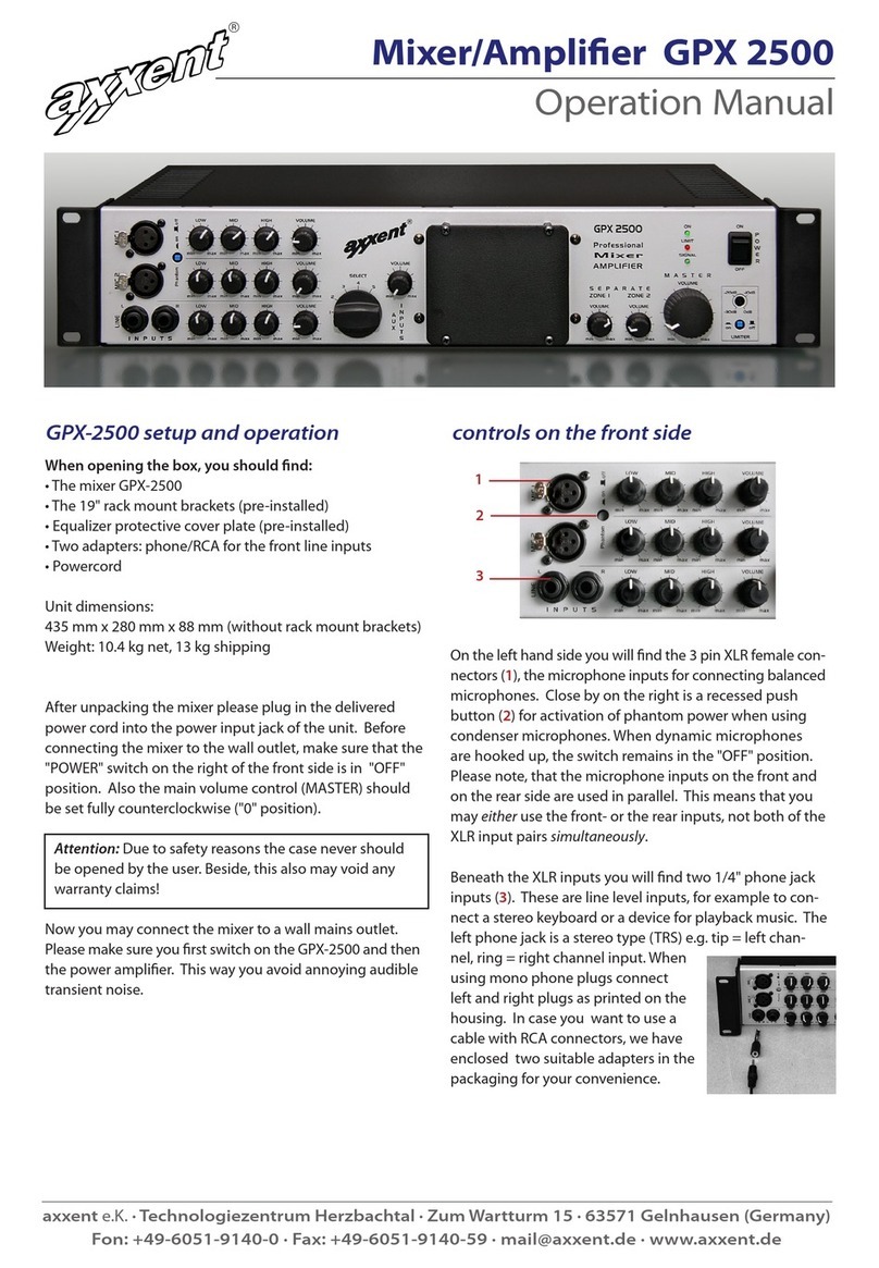
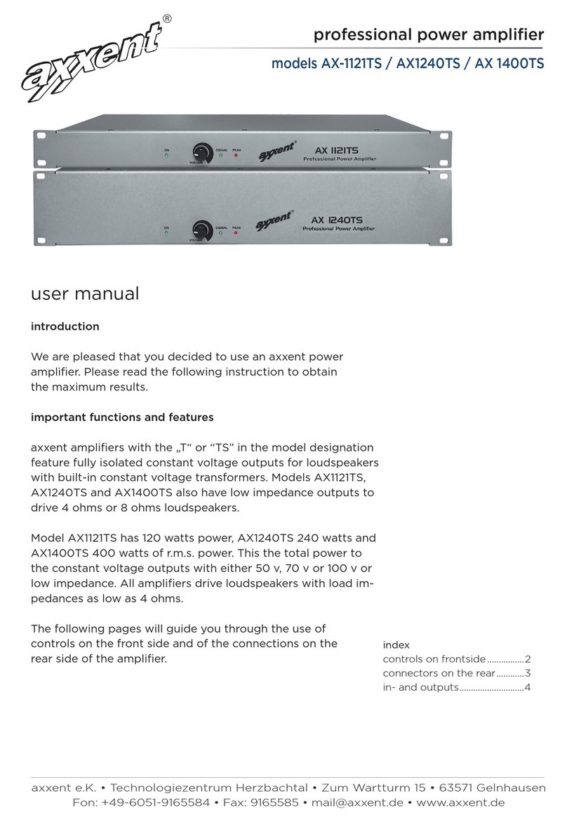
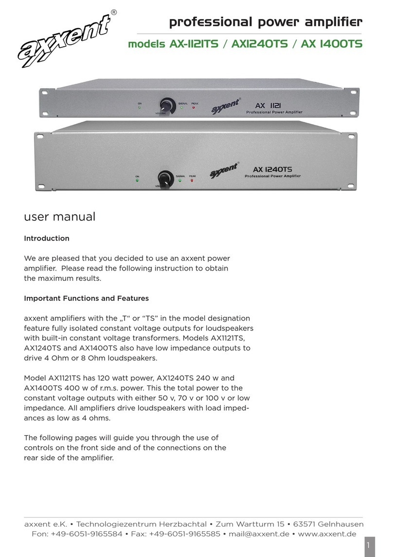
Axxent ISV 1090 User manual

axxent e.K. · Technologiezentrum Herzbachtal · Zum Wartturm 15 · 63571 Gelnhausen
fon: +49-6051-9165584 · fax: 9165585 · mail@axxent.de · www.axxent.de
User Manual
®
ISV 1090 Universal Induction Loop Amplifier
Withyourchoiceofthisaxxentinductionloopamplifieryouhavedecidedonahighqualityreliableandrugged
partofyoursoundsystemInordertogainthemaximumperformancewerecommendtocarefullyreadthis
manual
IMPORTANT!
Becauseofpotentialdangeroushazardtheusermay
operateonlythecontrolsonthefrontsideoftheunit
Allinternalsettingsdescribedonthefollowingpages
shouldbeadjustedbyqualifiedservicepersonnelonly
–thesameappliestoopeningthemetalcase(riskof
electricshock)
!
NOTE
The induction loop amplifier ISV1090 is contained in a
standard 19” rack case with mounted rack ears. It may
also be used as a table top unit with its rubber feet.
Rack mounting: when the unit is intended for rack
mounting, you should make sure whether the factory
pre-selected power setting for a coverage of up to 200
square meters would be sucient for your application
– if not, you will have to remove the housing top first.
Internal jumpers on the PCB (printed circuit board)
allow to alter these settings. On page 3 you will find the
instructions for changing the jumper setting.
Surface mounted unit: Please unscrew the rack ears
with the four screws each side. Changing the settings,
of course, is the same as described in the previous para-
graph.

axxent e.K. · Technologiezentrum Herzbachtal · Zum Wartturm 15 · 63571 Gelnhausen
fon: +49-6051-9165584 · fax: 9165585 · mail@axxent.de · www.axxent.de
User Manual
®
ISV 1090 Universal Induction Loop Amplifier
SETTINGS AND ADJUSTMENTS
First, the output power:
Since the Universal Induction Loop Amplifier ISV1090 not only is appropriate as a stand-alone amplifier, but also in
combination with one or more amplifiers connected, you are able to set the output power plus the operation modes.
Please keep in mind that the induction loop amplifier
ISV1090 can drive induction loops for venue surfaces
of up to 1000 square meters. In the maximum power
position the current reaches valued up to 8.8 A rms,
equivalent to approximately 12.7 A peak.
The ISV1090 provides adjustments for 4 dierent
power levels:
Up to 100 sqm, or 3 A rms
Up to 200 sqm, or 4.3 A (factory pre-set)
Up to 500 sqm, or 6.7 A rms
Up to 1000 sqm, 8.8 A rms
The factory setting is the second level for up to 200
sqm, 4.3 A. Other settings for power/coverage are ea-
sily made by changing the internal jumper position (see
schematic on next page)
Obviously, changes of factory settings can only be
made when you remove the steel cover. Important:
before you remove the cover, unplug the power cord.
All changes may be made only by qualified technicians
and not by consumers/endusers!
The following instruction explains the setting of the
two xlr microphone inputs sensivity. Factory setting
is at 1.5 mV, which is an average sensitivity of dynamic
microphones. Using a small screwdriver, the sensitivity
may be reduced down to 150 mV. This a typical auxiliary
leve, for example for MP3 players.
Cable cross-section finding the right gauge (single conduc-
tor, insulated) for an impedance between .5 and 1 ohm.
Cable
Length
300
1 Ohm
250
200
175
150
125
100
75
50
25
0
0
0.5 1 1.5 2 2.5 3 3.5 4 4.5
5
Cable
CSA
(mm
2
)
0.5 Ohm
Alittleguidetoselect
cablediameter,
considringlooplength,
toachieve
recommended
impedancebetween0,5
to1Ohm.
Selection guide for correct wire
gauge: Wire should be single
conductor, stranded and the load
impedance between 0.5 to 1 Ohm.

axxent e.K. · Technologiezentrum Herzbachtal · Zum Wartturm 15 · 63571 Gelnhausen
fon: +49-6051-9165584 · fax: 9165585 · mail@axxent.de · www.axxent.de
User Manual
®
ISV 1090 Universal Induction Loop Amplifier
Internal settings
Input sensitivity for mic inputs 1 and 2
gain current limiting
Adjustment of the basis configurations via internal jumpers
power level gain jumper current limit jumper
up to 1000 sqm, 8.8 Arms no High: yes Mid: no Low: no
up to 500 sqm, 6.7 Arms no High: no Mid: yes Low: yes
up to 200 sqm, 4.3 Arms yes High: no Mid: no Low: yes
up to 100 sqm, 3.0 Arms yes High: no Mid: no Low: no
screwdriver adjustable in the range 1.5 to 150 mV
default value is 1.5 mV (input sensitivity line 1 & 2 = 150 mV)
Input LINE 2
Pin A+, A– balanced input
Pin V+ output 22 V DC, max. 1 A Pin
Pin GND ground
*22 VDC output serves as power supply for external microphone to line pre-amplifiers.

axxent e.K. · Technologiezentrum Herzbachtal · Zum Wartturm 15 · 63571 Gelnhausen
fon: +49-6051-9165584 · fax: 9165585 · mail@axxent.de · www.axxent.de
User Manual
®
ISV 1090 Universal Induction Loop Amplifier
Second, operation modes:
The ISV1090 has been developed to drive not only
single perimeter or figure-of-eight and similar loops,
but, with additional units and in combination with a 90°
phase shifter module (PSM90) complex low spill-over
loops.
Standard perimeter wire loops stray the induction signal
outside their borders by far. Therefore, multi-segment
induction loops are required to reduce this eect. Typi-
cally, adjacent rooms such as conference rooms, mul-
tiplex cinemas, and similar require such. Low spill-over
loops require careful lay-out that can be performed
only by experienced consultants/audio contractors.
Therefore, the operation mode has to be selected by jumper connectors inside. Modes are ...
The ISV1090 also may be connected with another one in parallel for more induction loops.
In this mode the Master settings should be used. All the inputs of the connected amplifiers may be mixed together.
Wiring diagram for the connection cable between two ISV1090, 3 pin 6.3 mm phone plug.
SINGLE
induction loop amplifier acting as
a stand-alone unit (Jumper setting
combinations A or B)
MASTER
induction loop amplifer with another
unit as SLAVE and inserted 90° pha-
se shifter module into the master
unit (jumper setting combinations
C, D or E)
SLAVE
amplifier connected to the master
(jumper settings F or G)
IMPORTANT!
In master/slave mode, ampli-
fication/gain settings of both
amplifiers should be identical.

axxent e.K. · Technologiezentrum Herzbachtal · Zum Wartturm 15 · 63571 Gelnhausen
fon: +49-6051-9165584 · fax: 9165585 · mail@axxent.de · www.axxent.de
User Manual
®
ISV 1090 Universal Induction Loop Amplifier
SINGLE mode
In SINGLE mode the device works as an independent induction amplifier. Here are schematic diagrams of possible
configurations A and B. The dierence is in using metal loss correction function:
When joining 2 SINGLE devices through MASTER/SLAVE Jack 6.3 connector we can mix the inputs of both devices.

axxent e.K. · Technologiezentrum Herzbachtal · Zum Wartturm 15 · 63571 Gelnhausen
fon: +49-6051-9165584 · fax: 9165585 · mail@axxent.de · www.axxent.de
User Manual
®
ISV 1090 Universal Induction Loop Amplifier
MASTER and SLAVE modes
This operation mode, using a master amplifier with plugged in phase shifter module and a second amplifer in slave
mode minimises overspill of the induction loop signal to adjacent rooms.
Then devices are connected through MASTER/SLAVE Jack 6.3 connector. One device works as MASTER (configura-
tion C, D or E) and has Phase-shifter-module put into its mainboard. Another device is SLAVE (configurations F or G)
and has no Phase-Shifter module. Induction loops connected to these two devices are laid out in a special overlapping
pattern.
Here are MASTER mode configurations C, D, E :

axxent e.K. · Technologiezentrum Herzbachtal · Zum Wartturm 15 · 63571 Gelnhausen
fon: +49-6051-9165584 · fax: 9165585 · mail@axxent.de · www.axxent.de
User Manual
®
ISV 1090 Universal Induction Loop Amplifier
Here are SLAVE mode configurations F, G:
Recommended MASTER-SLAVE connection is E-F type as follows:

axxent e.K. · Technologiezentrum Herzbachtal · Zum Wartturm 15 · 63571 Gelnhausen
fon: +49-6051-9165584 · fax: 9165585 · mail@axxent.de · www.axxent.de
User Manual
®
ISV 1090 Universal Induction Loop Amplifier
Here a photograph of the ISV1090 inside, showing on the left side the jumper bank for the operation mode setting, to
the right the 90° phase shifter module socket, and far right the jumpers for adjusting output power of the ISV1090.
This is a PSM90, 90° phase shifter module for operation master/slave, to be inserted into the master unit:
As already described on the previous pages, the universal induction loop amplifier ISV1090 allows you to choose from
four dierent power levels. So practically all power requirements for various venue sizes and auditoriums can be met
with one model – a really unique feature.
PHASE SHIFTER MODULE PSM90

axxent e.K. · Technologiezentrum Herzbachtal · Zum Wartturm 15 · 63571 Gelnhausen
fon: +49-6051-9165584 · fax: 9165585 · mail@axxent.de · www.axxent.de
User Manual
®
ISV 1090 Universal Induction Loop Amplifier
THE CONTROLS (Front)
MIC 1, MIC 2
Left on the front side you will note four control knobs. The
two left ones control the microphone input level. On the rear
you will find the two corresponding 3pin XLR connectors. As
already described on the previous pages, the input sensitivity
of these inputs may be altered via small internal potentiome-
ters, located on the printed circuitry board. Phantom power
(48 V) for condenser microphones can be activated separate-
ly for each input via DIP switches labelled „PHAN 2 1“ (lower
ON position).
DRIVE, DRIVE CURRENT
The DRIVE control sets the output power (output current) of
the amplifier indicated by the LED chain. The “normal” safe
level is represented by the green LEDs, while the red LEDs
should only be lit at absolute level peaks.
COMPRESSION
In the centre of the front side you see an LED chain, label-
led COMPRESSION. The bargraph indicates the amount of
compression, e.g. how much the dynamic range between the
lowest audible signal and the maximum peak levels are com-
pressed. This compression facilitates intelligibility especially
for the “quiet” low level signals, highly appreciated by hearing
impaired persons.
TEMP
The red TEMP LED lights when the maximum operating tem-
perature is exceeded. If it lights up continuously, the induction
loop is probably not properly sized or the amplifier is overdri-
ven. Please check out these potential trouble causing sources.
LINE 1, LINE 2
Right from the MIC potentiometers you will note two control
knobs for the line signals. The corresponding connectors are
also located on the rear side. Line 1 is a balanced 3pin XLR
connector (female), while LINE2 is equipped with a 4 pole
Phoenix connector. A+/A- and GND is the balanced line input,
while V+ with GND represents the 22 v DC output, intended
as power supply for external microphone preamplifiers.
HEADPHONE SYMBOL
This is the input connector for any type of headphones with
standard phone plug 3.5 mm in order to check the audio
signal for distortion or other anomalies.
METAL
This potentiometer allows compensation of frequency ano-
malies, caused by metal parts or tubes located in vicinity of
the induction loop. In order to determine these frequency
response anomalies, we recommend the use of an induction
loop measurement instrument.
POWER
Green LED indicator confirms activated POWER switch on
the right (ON).
axxent e.K. · Technologiezentrum Herzbachtal · Zum Wartturm 15 · 63571 Gelnhausen
fon: +49-6051-9165584 · fax: 9165585 · mail@axxent.de · www.axxent.de
User Manual
®
ISV 1090 Universal Induction Loop Amplifier
REAR SIDE
FUSE
This is the fuse holder for glass fuses 5 x 20 mm, 2 A with
“slow blow” characteristic. In case this fuse fails, please have
it replaced with the same type of fuse (by qualified service
personnel). In case this fuse blows again, please return the
device for repair to your dealer or the manufacturer
axxent e.K.
MASTER/SLAVE
6.3 mm phone jack,
3 pin
PHAN
48 V phantom voltage
singly switchable for
Mic 1 and Mic 2
LOOP
2 pin Phoenix connector
for the induction loop
connection
MIC 1 AND MIC 2
Identical 3-pin xlr female
connectors
LINE 1
3-pin xlr female connector
for line level input
LINE 2
4 pin Phoenix connector
with additional 22 VDC
output for remote mic/line
preamp voltage support
Declaration of ConformityCE
PRODUKT: Low Frequency Power Amplifier for Hearing Im-
paired Persons
MODEL:axxent ISV1090, professional induction loop amplifier
Product is designed for amplifying acoustic frequency signals,
to be used in systems for hearing impaired persons.
Producer of electronic devices in subject this declaration of
conformity hereby declares in sole responsibility that the
equipment specified above is in compliance with mentioned
directives and standards and conforms to the requirements of
the harmonized product standards.
Used directives and standards:
EMC regulation 2014/30/EU and the low voltage directive
2014/35/EU.Electro-magnetic susceptibility 2004/108/EG is
based on EN55032:2015, Class B; EN61000-3-2, -3. Further
EN55024:2010+A1:2015; EN61000-4-2, 3,4,5,6,8,11.Low voltage
directive EN60950-1 of 2006 +A11+A12+A2
Further, the product fulfills the requirements of the regulation
2011/65/EU of the European parliament and the council for
reduction of potential hazardous product in electrical and
electronic appliances.
The product emits a magnetic induction according to its
primary use according to standard EN 60118-4
PRODUCER:axxent e.K.
PLACE:63571 Gelnhausen, Germany, Zum Wartturm 15
NAME:Josef Becker
POSITION:Owner
DATE:June 25, 2018
Table of contents
Other Axxent Amplifier manuals

Axxent
Axxent AMV-7240 MKII User manual

Axxent
Axxent CLP2090 User manual

Axxent
Axxent AMV-7240 User manual

Axxent
Axxent AX-1121TS User manual

Axxent
Axxent AX2120TS User manual

Axxent
Axxent AX4120TS User manual

Axxent
Axxent AX-4120TS-D User manual

Axxent
Axxent GPX 2500 User manual

Axxent
Axxent AX1121TS User manual

Axxent
Axxent AX2150S User manual