Page : 3
________________________________________________________________________________________________
HYDRO’pH®, HYDR’ORP®, HYDRO’pH Duo®and HYDRO’pH/ORP®instructions
SUMMARY
1. General information ............................................................................................................................... 5
1.1. Using this document....................................................................................................................................................... 6
1.2. Warranty ........................................................................................................................................................................ 6
2. Safety Instructions .................................................................................................................................. 7
2.1. Controllers use ............................................................................................................................................................... 7
2.2. User’s obligations........................................................................................................................................................... 7
2.3. Risk prevention .............................................................................................................................................................. 7
3. Specifications........................................................................................................................................... 9
3-1 Execution of standard HYDRO range equipments..................................................................................................... 9
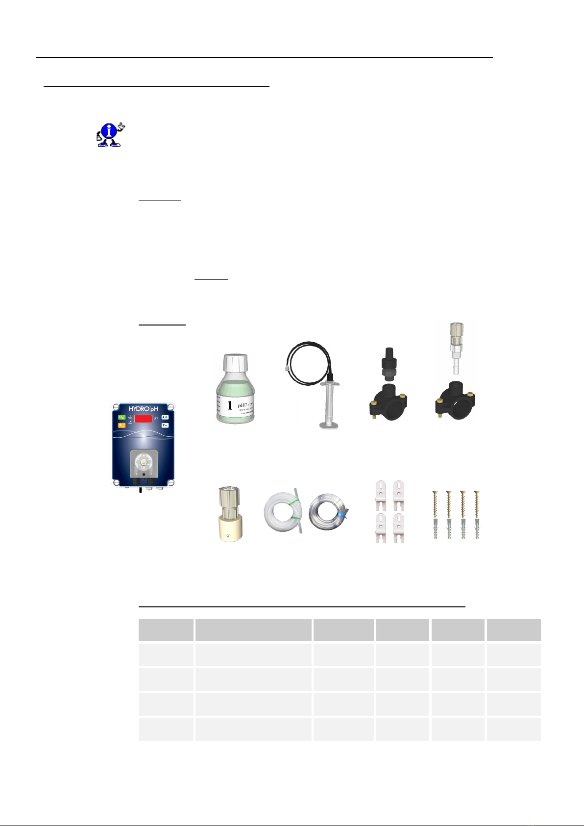
a) HYDRO’pH®............................................................................................................................................................... 9
b) HYDR’ORP®............................................................................................................................................................. 10
c) HYDR’ORP®with power socket 2P+E ................................................................................................................... 11
d) HYDRO’pH Duo®..................................................................................................................................................... 11
3-2 General specifications of HYDRO controllers …...................................................................................................... 14
3-3 Electronical features and functions ........................................................................................................................... 14
a) Electronic part........................................................................................................................................................... 14
b) General functions ...................................................................................................................................................... 14
c) General functions of control..................................................................................................................................... 14
d) Measurement scales of analysers ............................................................................................................................. 14
3-4 General dimensions of boxes and wall mounting dimensions .................................................................................. 15
4Installation and connections ................................................................................................................ 16
4-1 Transport and storage of HYDRO’pH®, HYDR’ORP®and HYDRO’pH/ORP®................................................... 16
4-2 Wall mounting terms ................................................................................................................................................... 16
4-3 Wall installation of control device .............................................................................................................................. 16
4-4 Installation of pipe saddles for sensors and products injection ............................................................................... 17
a) Mounting procedure of pipe saddles ....................................................................................................................... 19
b) Mounting procedure for the sensors connection kit............................................................................................... 19
c) Mounting procedure for pipes connection kit ........................................................................................................ 20
d) Mounting procedure of flexible sunction pipe ........................................................................................................ 21
f) Connecting the pH and/or ORP sensors on the Hydro’ box ................................................................................. 22
4-5 Commissioning /Electrical connections...................................................................................................................... 23
a) General connections.................................................................................................................................................. 23
b) Position of the pH control direction (HYDRO’pH®and HYDRO’pH/ORP®)..................................................... 24
c) Internal connections of the tank bottom detector .................................................................................................. 24
d) Changing the internal protection fuse..................................................................................................................... 25
4-6 Filling the tanks of chemicals...................................................................................................................................... 25
5HYDRO controllers presentation........................................................................................................ 26
5-1 General operation ........................................................................................................................................................ 26
5-2 Commands of keyboards and displays....................................................................................................................... 27
5-3 On/Off switch ............................................................................................................................................................... 28
5-4 Safety breaker circuit uses in the HYDR’ORP with socket ..................................................................................... 28
5-5 Sensor(s) input(s) ......................................................................................................................................................... 28
6HYDRO’ controllers programming.................................................................................................... 29
6-1 Opening remarks ......................................................................................................................................................... 29
6-2 Procedures .................................................................................................................................................................... 29
a) « Hidden mode » Only used by technicians ............................................................................................................ 29
A. Maximum operating time of the pH dosing pump per cycle ........................................................................... 29
C. pH and/or ORP controllers proportional bands............................................................................................... 31
D. Changing the minimum terminal of the pH control range .............................................................................. 33
E. Changing the maximum terminal of the pH control range.............................................................................. 34
F. Polarity of the input « CAD »............................................................................................................................. 35
G. Record of the last reported error ....................................................................................................................... 35
b) « Normal mode » Used by the customer.................................................................................................................. 36