7
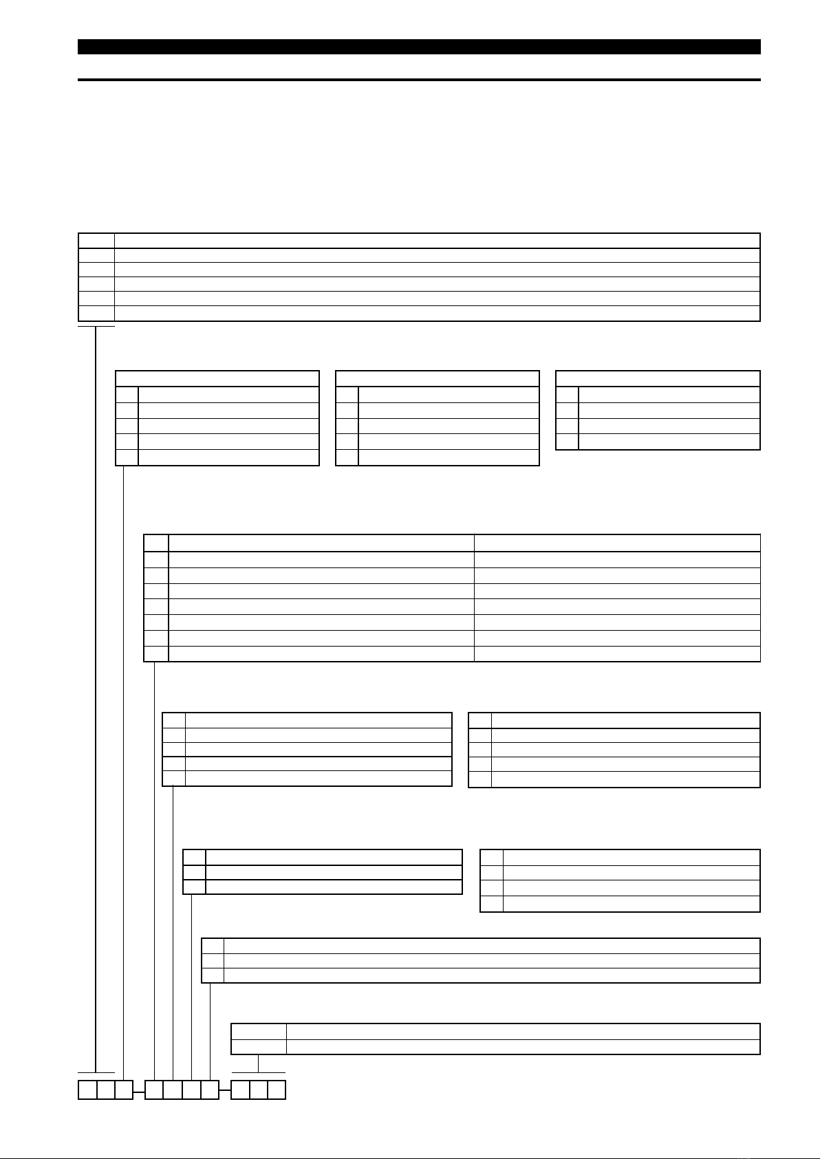
MODEL IDENTIFICATION
Acomplete measuring system consists of:
1 Code for Vizual®MLI cage (for modified models or adders, put an “X” in front of the closest matching order code and
specify the modifications separately. E.g. XGSD-H23F-120 X = with material certification EN 10204-3.1
2. Always specify operating temperature/ pressure/ S.G. and viscosity if > 80 cP
3. Code for options:
-Reed chain transmitter / Micro-switches / Bi-stable (reed type) switches: consult factory
- Scale: standard 304 stainless steel
Code: 032-3930-xxx: scale in cm. Consult factory for tailor made scales
3-last digits represent the measuring range in cm increments (e.g. 120 = 120 cm)
Gcomplete code for Vizual®Magnetic Level Indicator
PROCESS CONNECTION: SIZE
0 1/2"
13/4"
21"
31 1/2"
4 2" ➀
PROCESS CONNECTION: STYLE
NNPT-F coupling (size: max 1")
SSocket weld coupling (size: max 1")
FFlanged (all sizes)
Z DN 15
A DN 20
B DN 25
CDN 40
D DN 50 ➀
3 150 lbs - RF flange
4 300 lbs - RF flange
5 600 lbs - RF flange
APN 16 EN 1092-1 B1 flange
BPN 25/40 EN 1092-1 B1 flange
DPN 63 EN 1092-1 B2 flange
E PN 100 EN 1092-1 B2 flange
BASIC MODEL NUMBER - ANSI CLASS CAGES IN 316/316L (1.4401/1.4404) - FLANGES AND CAGE
MATERIALS OF CONSTRUCTION
CAGE & FLANGES: 316/316L (1.4401/1.4404) – FLOAT: 316 Ti (1.4571) except code A: Titanium
SPECIFIC GRAVITY RANGE AND FLOAT HYDROTEST PRESSURE➀
ALWAYS SPECIFY EXACT OPERATING S.G, max temp & pressure when ordering Vizual
PRESSURE RATING - FLANGE TYPE (if applicable)
030 minimum 30 cm (12")
5 7 0 maximum 570 cm (224")
GA Side/bottom process connection with sealed top cap
G B Side/bottom process connection with flanged top
G S Side/Side process connection with sealed top cap
G R Side/Side process connection with flanged top
GT Top/bottom process connection with sealed top cap
G U Top/bottom process connection with flanged top
Hydrotest 36 bar @ +40 °C
A0,56 to 0,60
B0,61 to 0,70
C0,71 to 0,80
D0,81 to 0,90
E0,91 to 1,50
Hydrotest 52 bar @ +40 °C
F0,58 to 0,61
G0,62 to 0,70
H0,71 to 0,80
J0,81 to 0,90
K0,91 to 1,50
Hydrotest 85 bar @ +40 °C
M0,62 to 0,70
N0,71 to 0,80
O0,81 to 0,90
P0,91 to 1,50
Indication rail without scale ➀Temperature range
HAluminium rail / SST flappers / Polycarbonate window -20 °C upto +160 °C (-5 °F upto +320 °F)
JAluminium rail / SST flappers / Polycarbonate window -50 °C upto +125 °C (-60 °F upto +260 °F)
KAluminium rail / SST flappers / Polycarbonate window -20 °C upto +200 °C (-5 °F upto +390 °F)
LAluminium rail / SST flappers / Polycarbonate window -20 °C upto +250 °C (-5 °F upto +480 °F)
MAluminium rail / SST flappers / Glass window -20 °C upto +300 °C (-5 °F upto +570 °F)
NAluminium rail / SST flappers / Glass window -20 °C upto +350 °C (-5 °F upto +660 °F)
PAluminium rail / SST flappers / Glass window -20 °C upto +400 °C (-5 °F upto +750 °F)
ANSI EN/DIN
➀See options for scales
➀Consult factory for low S.G, interface applications or high pressure floats
➀2"/DN 50 process flanges are machined to 1" size
Note: segmented cage for lengths > 570 cm (224"), consult factory
MEASURING RANGE (as per drawings at left page) – per 1 cm (0.39") increments