562E
1
IntroductionChapter 1
Typical gate setups, such as drum miking or
cleaning up multitrack recordings, all face the
same difficulty: how to apply a precise trigger to
imprecise, organic signal sources. Much to the
frustration of audio engineers, instruments and
vocalists produce natural audio waveforms, and
nature is rarely consistent. When nature meets
machine in audio processing, the results can
sound like the snap, crackle and pop you’d prefer
in your cereal, not your audio. Most gates offer
only one solution to this problem: open faster.
While they measure performance in microsec-
onds of "how fast", Symetrix is rewriting the rules
on how to open. The dual channel 562E
WindowingExpander/Gateexploitsournewly-
developed, proprietary technology to enhance
gatingandexpandercontrol. Ultimatelythe562E
delivers unparalleled fidelity to any audio signal.
GATING:Gatesmaybeusedtocleanup
virtually any type of musical instrument or audio
sound effect, but perhaps their most common use
is on drum and percussion tracks. The 562E
employs two unique tools for detecting and
controlling these audio events.
WindowAdvanceisaproprietarysystemfor
recognizing the signal to be gated. In simple
terms, it virtually creates the impossible: a gate
that opens just ahead of the audio signal. It
creates this impression by moving the statistical
energy center of the gated signal forward in time.
WindowAdvancepermitstheusertosubtlydelay
the signal energy, centering it within the enve-
lope. Through this function, the 562E’s gate
passes the entire leading edge of the audio
waveform. It accomplishes this because the gate
opens before the signal passes through the VCA.
WindowAdvanceeliminatesthenoisesand
chopped-off waveforms created by traditional
gates that struggle to open as quickly as possible
after the signal arrives.
AutoWindowing is a processing technique that
allows the user to maintain better control of the
gate envelope parameters. Its dynamic smooth-
ing process reduces “pops” and “clicks” that can
occur at fast attack settings. These nasty noises
are typically produced by envelope edges,
overshoot and instabilities. Even gates that claim
to open within microseconds fail to recognize the
reality underlying these problems: naturally
occurring waveforms do not have consistent
leadingedges. Incontrast,AutoWindowing
derives its trigger signal from the “time center” of
the leading edge of the audio waveform. This
reduces trigger uncertainty, jitters, and attack
distortion. AutoWindowingyieldsanenvelope
that is consistent and natural-sounding. It also
increases envelope consistency by eliminating
the artificial “drop off” that occurs in most gates
at the end of the release cycle. In the 562E the
signal smoothly and continuously decreases at
the end of the release cycle, creating a much more
pleasing sound.
EXPANSION: The562Ealsopermitsusersto
have a distinctive choice between gating and
expansion. A downward expander is similar to a
gate, but the expander substitutes RATIO control
for the gate’s RANGE control. The expander is
ideal for tasks requiring more subtle control. To
all possible uses for an expander, the 562E
delivers superior performance through unique
technology. Even the 562E’s ratio circuitry is
special. The ratio automatically reverts to 1:1
when the signal approaches 25dB below the
threshold. This prevents any low level modula-
tion of the expanded signal.
For the first time, open your ears to all the clear
audio you wanted without any revenge from the
processor. Experience a quantum leap forward in
gatetechnologywiththeSymetrix562EWindow-
ingExpander/Gate.
0
TIME RELEASE
TIME
1 Sec 500ms
EXPANDER RATIO
GATE RANGE
1:380
2.5 Sec4 Sec 30ms
CHANNEL 2CH2 SIDECHAIN PROCESSING
TIME(dB) ATTACK
0 60ms
GAIN (dB)
REDUCTI0N
ABOVE
BELOW
30
MAX 12
3
THRESHOLD
300ms+20 AUTO
60
OFF -40
MIN
HIGH CUT
20K
200Hz1K
50Hz 4K
OUTPUT
15Hz
KEY LISTEN
ASSIGN 20Hz
LOW CUT
40K
1K 400Hz
IN GATE/EXP. 10Hz
W/FILTER
WINDOW
ADVANCE
50ms
HOLD
CHANNEL 1
TIME GATE RANGE
EXPANDER RATIO
500ms 0
HOLD
TIME
ATTACK
TIME
60ms 1 Sec
RELEASE
1:3
2.5 Sec 80dB
4 Sec300ms 50ms 30ms
(dB)
THRESHOLD
ABOVE
BELOW
0
HIGH CUT
WINDOW
30
MAX 12
20K
4K ADVANCE 3
REDUCTI0N
GAIN (dB)
-40 +20
60
OFF
40K
400Hz MIN AUTO
LOW CUT
OUTPUT
200Hz15Hz
ASSIGN 20Hz 50Hz
EXT.KEY
E
KEY LISTEN
1K10Hz
IN GATE/EXP.
BYPASS W/FILTER
562
WINDOWING
EXPANDER/GATE
CH1 SIDECHAIN PROCESSING
1K
BYPASS
EXT.KEY
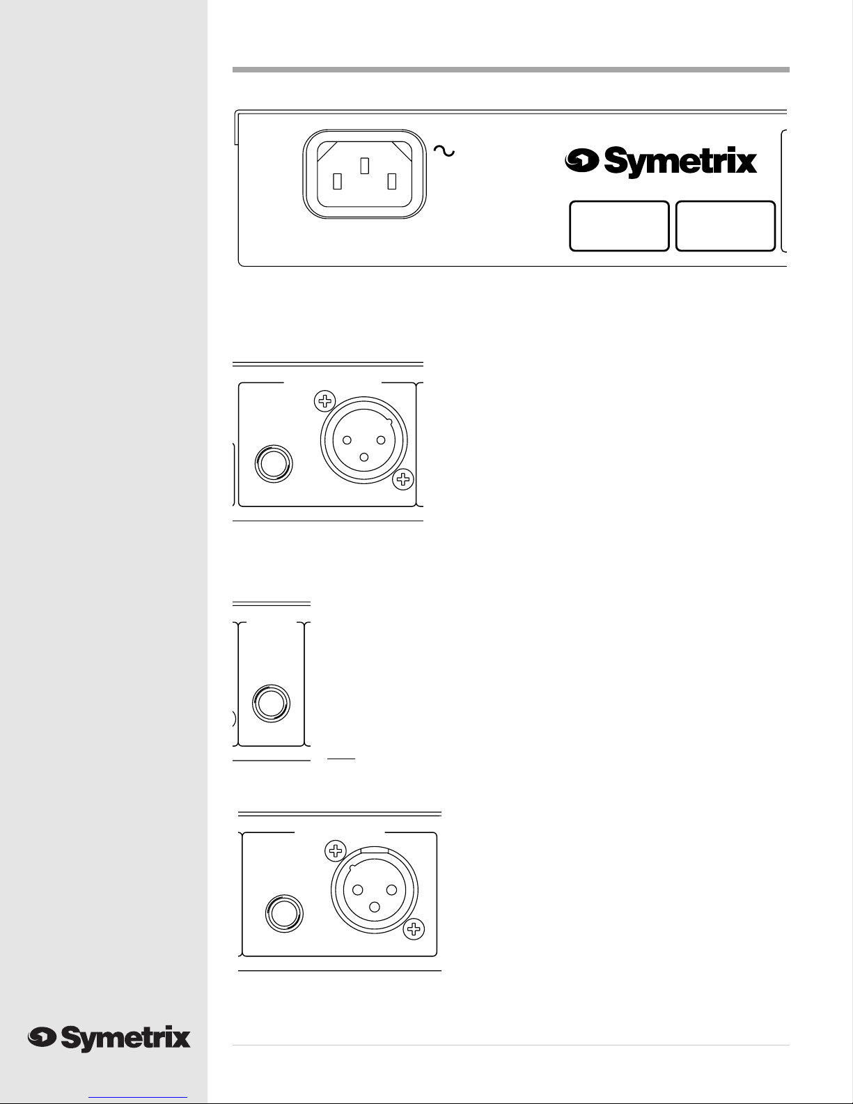
CHANNEL 1 INPUT
UNBALANCED
BALANCED/
BALANCED
KEY
INPUT
BALANCED/
BALANCED
OUTPUTS
UNBALANCED
CHANNEL 1 OUTPUT
BALANCED
TYPICAL CONNECTIONS
13
SIDECHAIN
1
3
2
LOW(-)=PIN 3
HIGH(+)=PIN 2
GROUND=PIN 1
1/4"BALANCED
BALANCED
INPUTS
TIP=HIGH(+)
RING=LOW(-)
BALANCED
SLEEVE=GROUND GROUND
SIDECHAIN OUT
KEY INPUT
2
SIDECHAINSIDECHAIN
UNBALANCED
BALANCED/KEY
INPUT
CHANNEL 2 OUTPUT
BALANCED
E
562
WINDOWING EXPANDER/GATE
MANUFACTURED IN LYNNWOOD, WASHINGTON USA
UNBALANCED
BALANCED/
AC INPUT
18 WATTS
MAXIMUM
FABRIQUÉ AUX E.-U. PAR SYMETRIX INC., LYNNWOOD, WA USA.
RÉFÉREZ TOUTE RÉPARATION À UN TECHNICIEN QUALIFIÉ.
CHANNEL 2 INPUT
Front panel
Rear panel