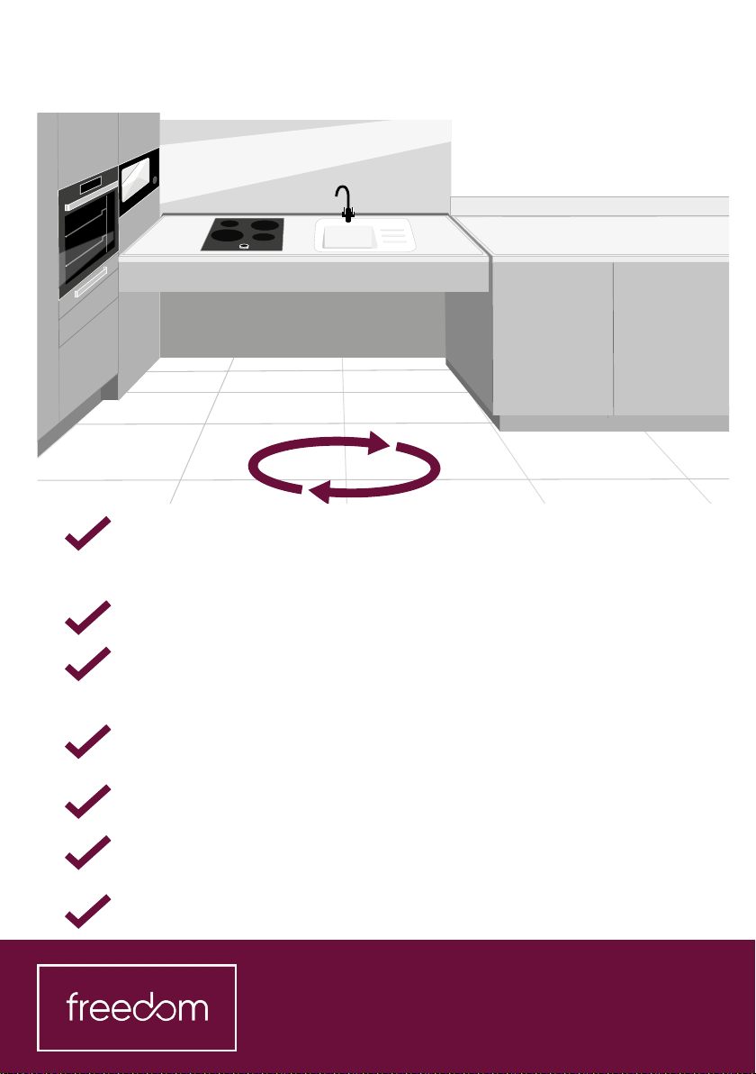
Symphony freedom User manual

2
Contents Page
Preparation and Setting out Page 4-5
Wall Reinforcement Page 6-8
The Ropox Frame Installation Page 10-50
Starting the Installation Page 10-19
Building Ropox Frame (including Spindle and motor) Page 20-37
Fixing L-shape frame Page 38-43
Aligning frame Page 44-45
Packers Page 46-48
L-shape frame packers Page 47
Manual Rise and Fall packers Page 48
Front Fascia Fixings Page 49-50
Worktop Installation Page 51-55
Maia Waterfall worktop Page 51
Fixing worktop to Ropox frame Page 52-55
Fascias Page 56-59
Manual Rise and fall Page 60-64
Installing the Handle Page 60-64
Electric Rise and Fall Page 65-78
Wiring the Control Box Page 69
Safety Strip Page 70-72
Control Switch Page 74-75
Sink Installation Page 76
Testing Page 77-78
Kitchen Installation Page 79-92
Unit Installation Page 79-80
Concealment Panel Page 81-89
Extractor Page 90
Handles Page 91
Splash back Page 92

4
Check walls are suciently reinforced behind electric and manual
rise and fall worktops, worktops on fixed brackets, and electric wall
units (see page 102).
Floor should be fully tiled before fitting.
For rise and fall worktops, do not tile any area of the kitchen wall
prior to fitting. When fitting worktops on fixed brackets, finish the
wall behind with a suitable material before fitting.
Plasterboard is not suitable for worktops on fixed brackets. Ensure
the wall is covered with a suitable material.
Drainage height should be below 400mm.
Flexible hoses are required for hot, cold, and waste water on rise
and fall and fixed worktops.
Ensure suitable fixings are used.
Preparation

5
<400mm
Setting Out
Start with the sink and hob worktop area when setting out and fitting.
Check that a turning circle of 1.5m x 1.5m can be achieved once all units
are in place.
The angle of the tall units can be adjusted in relation to the wall, after
the sink and hob worktop is set out. This ensures the sink and hob work-
top section is at right angles to the rest of the units.
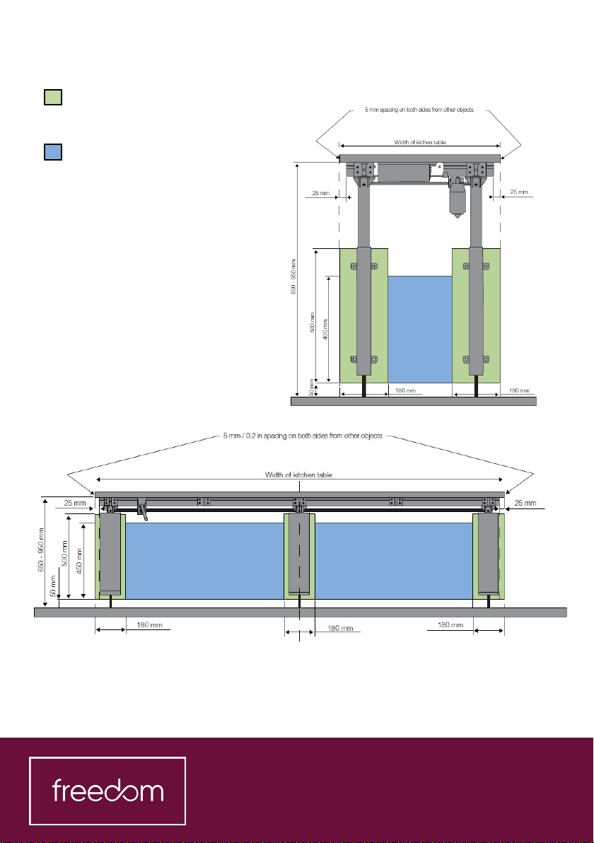
5mm gap required at either end of rise and fall worktops. Ensure this is
allowed for when setting out.
5mm gap required behind rise and fall worktops, once wall covering is
fitted. Allow 13mm gap behind when setting out.
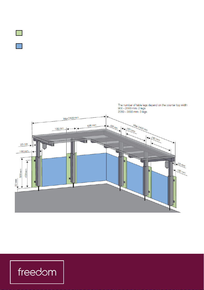
Base units will be shown on the plan as battened o the wall by 50mm,
with 650mm worktops. Ensure this is accounted for when setting out. The
rise and fall worktops will be 637mm, to allow for a 13mm gap behind. The
front of the rise and fall and fixed worktops will be flush with each other.
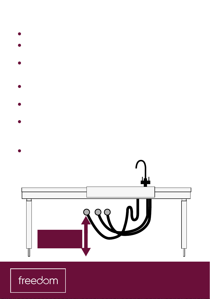
Fixed worktop brackets should be set at an appropriate height for the
user, or as advised by the site manager. Height from the floor can be
779mm, 819mm, 859mm, 899mm, or 939mm.

6
Minimum area for reinforcement of wall. Wall material must be suitable
for screw mounting
Area for electric and plumbing installations
Max. load 150kg evenly distributed over the worktop up to 300cm in width,
according to DS/EN 12182.
Minimum load Capacity per screw/bolt:
40kg (straight run), 200kg (right angle)
The fitter should always consider the material, condition and strength of
the wall and use screws and plugs suitable for the specific wall type.
Please note: the frame should not be fixed directly to the wall. Use the
distance brackets supplied to space the legs from the wall by 70mm. See
page 22 for more detail.
Wall reinforcement

7
Minimum area for reinforcement
of wall. Wall material must be
suitable for screw mounting
Area for electric and plumbing
installations
Max. load 150kg evenly distributed
over the worktop up to 300cm in
width, according to DS/EN 12182.
Minimum load Capacity per screw/
bolt:
40kg (straight run), 200kg (right
angle)
The fitter should always consider
the material, condition and
strength of the wall and use screws
and plugs suitable for the specific
wall type.
Wall reinforcement
Please note: the frame should not be fixed directly to the wall. Use the
distance brackets supplied to space the legs from the wall by 70mm. See
page 22 for more detail.

11
If the client is a
wheelchair user, then
the underside of the pull
out shelf should finish
1cm above the client’s
knees. The height of
the shelf should have
been calculated by the
designer and added to
the plan.
2.
For generic kitchens or displays, set the
plinth at standard height.
When plinths are at standard height,
the distance to the underside of the pull
out worktop frontal is 704mm. Reduce
or increase plinth height to adjust shelf
height.
Check the required height of pull out shelf under oven.
1cm
704mm

13
If the design includes a microwave in the corner above the adjacent rise
and fall worktop, and a housing is not provided, fit at 993.5mm from floor.
When at its highest position, the top of the rise and fall worktop will exceed
the bottom of microwave - this is ok if microwave with flat control panel
(i.e. Ne) is fitted.
4.
993.5mm

18
Using the plan, the minimum distances below, and the diagrams shown,
calculate the position of the hob and sink.
Cut outs must be 100mm minimum from ends.
Minimum distance between sink bowl and hob = 300mm.
Minimum prep space on other side of hob = 540mm.
8.
300mmMin.540mm 100mm
If these distances cannot be achieved, contact the designer for advice.
left to right or right to left
Worktop end Worktop end
Hob Sink bowl Drainer

20
Based on the hob and sink cut out positions, calculate the position of the
support arms. This will then dictate the position of the legs.
On straight runs, one arm will sit on top of each leg at each end of the
worktop.
Two arms should be positioned either side of the hob, as close as
possible to the cut out.
One arm should be positioned under the drainer, as close to the sink
bowl as possible.
9.
The legs should be positioned so that an arm can sit above each one. Use
the calculated positions of the support arms to mark out where to fit the
legs on the back wall.
Other Symphony Indoor Furnishing manuals
Popular Indoor Furnishing manuals by other brands

YOTRIO
YOTRIO Target Martti FRS60725 Assembly instructions

CONFORAMA
CONFORAMA LIT COZY Assembling Instruction

Walker Edison
Walker Edison OW60VINDT Assembly instructions

Sanus Systems
Sanus Systems T20/20 Assembly instructions

Core Products
Core Products Nairn NR218 Assembly instructions

comfortel
comfortel Comet owner's manual