Synergic PowerMig 400-4 User manual

73502
-
1212
11
-
V1
P
: 10
-
16
/
28
-
36
P
: 17
-
22 / 28
-
36
P
: 23
-
27
/
28
-
36
P
: 3
-
9
/
28
-
36

2
I
II
100
kg
Tube capillaire
/
capillary tube
Tube capillaire
/ capillary tube
Gaine té
lon
/ Liner or alu
Gaine acier
/ liner or steel
①
①①
①
⑮
⑮⑮
⑮
⑯
⑯⑯
⑯
②
②②
②
③
③③
③
④
④④
④
⑤
⑤⑤
⑤
⑥
⑥⑥
⑥
⑬
⑬⑬
⑬
⑦
⑦⑦
⑦
⑧
⑧⑧
⑧
⑨
⑨⑨
⑨
⑪
⑪⑪
⑪
⑩
⑩⑩
⑩
⑫
⑫⑫
⑫
PowerMig 400
PowerMig 400PowerMig 400
PowerMig 400-
--
-4
44
4
⑭
⑭⑭
⑭
⑫
⑫⑫
⑫
PowerMig Twin 400
PowerMig Twin 400PowerMig Twin 400
PowerMig Twin 400-
--
-4
44
4
⑭
⑭⑭
⑭
⑫
⑫⑫
⑫
PowerMig Generator 400W
PowerMig Generator 400WPowerMig Generator 400W
PowerMig Generator 400W
PowerMig 400
-
4
PowerMig Twin 400-4
PowerMig Generator 400W

3
DESCRIPTION
Merci de votre choix ! Afin de tirer le maximum de satisfaction de votre oste, veuillez lire avec attention ce qui suit :
Les PowerMig 400-4, PowerMig Twin 400-4 et PowerMig Generator 400W sont des ostes de soudure semi-
automatique « synergic » sur roues, ventilés our le soudage (MIG ou MAG). Ils sont recommandés our le soudage
des aciers, des inox, des aluminums. Leur réglage est sim le et ra ide grâce à leur fonction « vitesse de fil
synergique ». Ils fonctionnent sur une alimentation 400V tri hasée. Le PowerMig Twin 400-4 eut accueillir le
dévidoir sé aré SATELLITE 4R (ref. 034150) ; Pour fonctionner, le générateur PowerMig Generator 400W doit être
utilisé avec le dévidoir sé aré SATELLITE 4W uniquement. (ref. 034167)
ALIMENTATION ÉLECTRIQUE
Le courant effectif absorbé (I1eff) our les conditions d'utilisation maximales est indiqué sur l'a areil. Vérifier que
l'alimentation et ses rotections (fusible et/ou disjoncteur) sont com atibles avec le courant nécessaire en utilisation.
L'a areil doit être lacé de façon telle que la fiche de rise de courant soit accessible.
Ne as utiliser de rallonge ayant une section inférieure à 4 mm². Ces a areils sont livrés avec une rise 32A de
ty e CEE 7/7. Ils doivent être reliés à une rise 400V 3Ph. AVEC terre rotégée ar un disjoncteur 32A et un
différentiel 30mA.
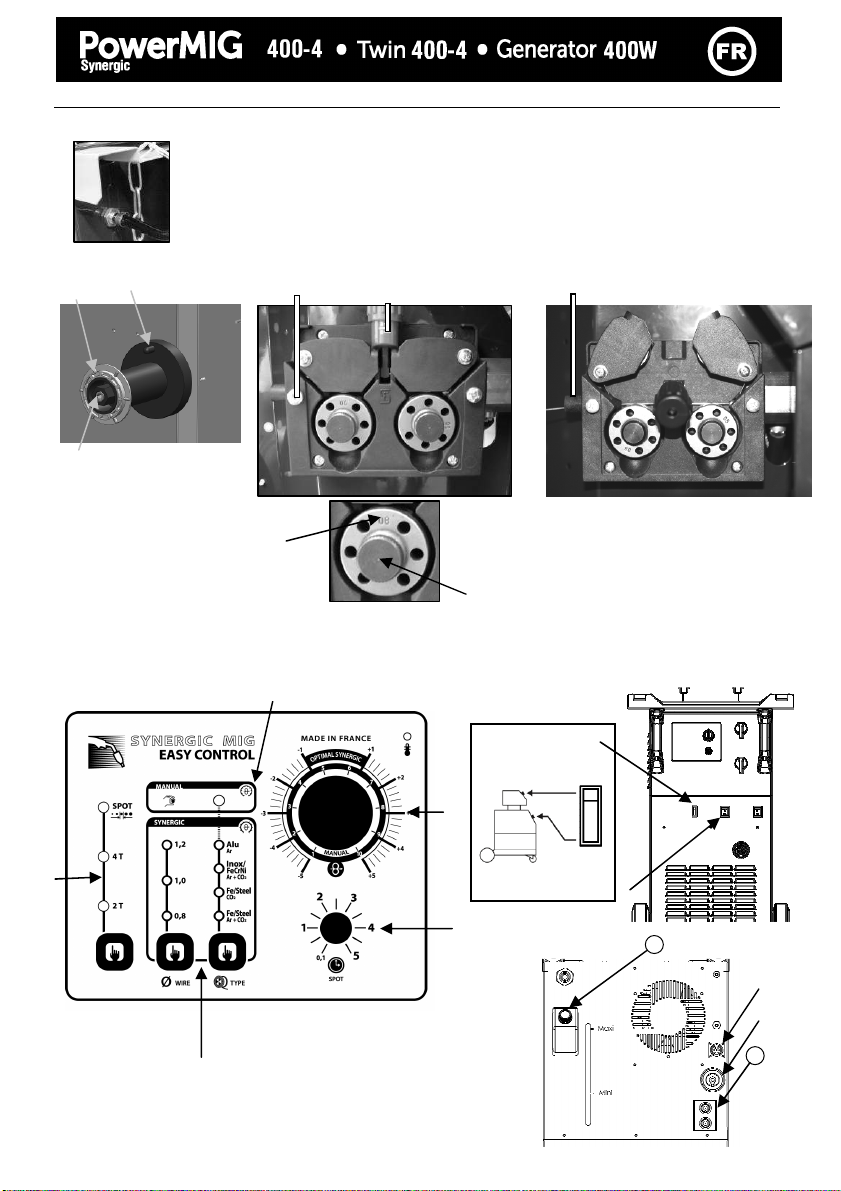
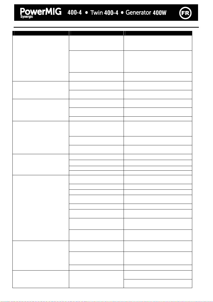
DESCRIPTION DU POSTE
① Interru teur marche – arrêt
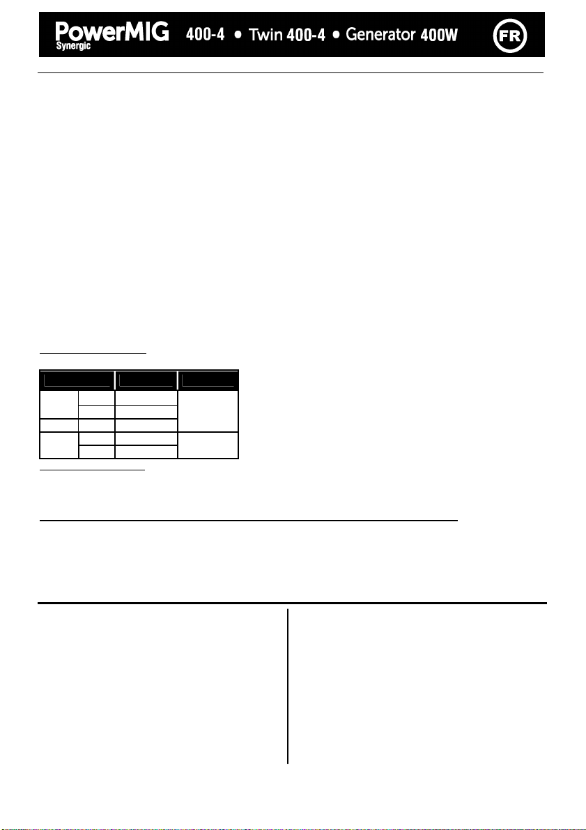
② Réglage de uissance ar 2 commutateurs (2 et 7
ositions) ermet d’ajuster la tension de soudage en
sortie de générateur. Le réglage de tension de sortie
est ro ortionnel à l’é aisseur du matériau à souder.
(cf age 6)
③ Clavier de réglages des aramètres de soudage
(mode manuel ou automatique).
④ Raccords torche au standard euro éen.
⑤ Voyant de rotection thermique sur le clavier de
commande : signale une cou ure thermique lorsque
l’a areil est utilisé de façon intensive (cou ure de
lusieurs minutes).
⑥ Su ort torches avant
⑦ Câble d’alimentation (5m)
⑧ Sortie ince de masse.
⑨ Su ort bouteilles
(maxi une bouteille de 10m
3
).
⑩ Chaine de fixation our bouteilles.
Attention : bien ixer la bouteille
⑪ Su ort bobine Ø 200/300 mm.
⑫ Entrée gaz
⑬ Su ort cables arrière.
⑭Panneau arrière de connexion our dévidoir
sé aré (PowerMig Twin 400-4 et PowerMig
Generator 400W)
SOUDAGE SEMI-AUTOMATIQUE EN ACIER / INOX (MODE MAG)
Cet a areil eut souder du fil acier et inox de 0,8/1/1,2 et du 1,6mm occasionellement. (figure
⑮
)
Il est livré d’origine our fonctionner avec du fil Ø 1 mm en acier( galets Ø 0,8/1 acier/inox)
Lorsque vous utilisez du fil de diamètre 1 mm ; il convient d’utiliser une torche avec un tube contact de 1. Le galet
du moto-dévidoir est un galet réversible 0,8 / 1mm. Dans ce cas, le ositionner de telle façon à lire 1 mm sur le flanc
visible du galet.
L’utilisation en acier ou inox nécessite un gaz s écifique au soudage argon + CO
2
(Ar + CO
2
).La ro ortion de CO
2
varie selon l’utilisation. Pour le choix du gaz, demander conseil à un distributeur de gaz. Le débit de gaz en acier se
situe entre 10 et 20 L/min selon l’environnement et l’ex érience du soudeur.
Pour souder en 1,6mm, se munir de galets et d’une torche ada tés.
SOUDAGE SEMI-AUTOMATIQUE ALUMINIUM
Cet a areil eut souder du fil aluminium de 1 mm et 1,2 mm. (figure
⑯
)
Pour souder l’aluminium, il faut utiliser un gaz neutre: argon ur (Ar). Pour le choix du gaz, demander conseil à un
distributeur de gaz. Le débit du gaz se situe entre 15 et 25 L/min selon l’environnement et l’ex érience du soudeur.
Ci-dessous les différences entre l’utilisation soudage acier et soudage aluminium :
-La ression des galets resseurs du moto-dévidoir sur le fil : mettre un minimum de ression afin de ne as
écraser le fil.
-Tube ca illaire : retirer le tube ca illaire avant de connecter la torche aluminium avec une gaine en téflon.
-Torche : utiliser une torche s éciale alumimium. Cette torche ossède une gaine téflon afin de réduire les
frottements.
- NE PAS couper la gaine au bord du raccord ! cette gaine sert à guider le fil à artir des galets.
(cf schéma ⑯)
Tube contact : utiliser un tube contact SPECIAL aluminium corres ondant au diamètre du fil.

4
IV
V
①
①①
①
②
②②
②
③
③③
③
④
④④
④
⑤
⑤⑤
⑤
⑨
⑨⑨
⑨
⑩
⑩⑩
⑩
⑪
⑪⑪
⑪
⑫
⑫⑫
⑫
⑬
⑬⑬
⑬
⑭
⑭⑭
⑭
⑥
⑥⑥
⑥
⑦
⑦⑦
⑦
⑧
⑧⑧
⑧
⑨
⑨⑨
⑨
16
15
⑰
⑱
⑲
⑲⑲
⑲
⑳
⑳⑳
⑳

5
PROCÉDURE DE MONTAGE DES BOBINES ET DES TORCHES :
• Ouvrir la tra e du oste.
• Positionner la bobine en tenant com te de l’ergot d’entrainement
③
du su ort bobine. Pour monter une
bobine de 200mm, installer au réalable un ada tateur sur le su ort (ref. 042889).
• Régler le frein de la bobine
④
our éviter lors de l’arrêt de la soudure que l’inertie de la bobine n’emmêle le fil.
Serrer ensuite fermement la vis de maintien ②. (ne as serrer tro fort)
• Les galets moteur
⑧
sont des galets double gorge (Ø 0,8/ Ø 1 ou Ø 1/ Ø 1,2). L’indication qu’on lit sur le galet
est celle que l’on utilise. Pour un fil de Ø 1 mm, utiliser la gorge de Ø 1.
• Pour la remière mise en service :
odésserrer la vis de fixation du guide fil ⑤
olacer les galets, bien serrer leur vis de maintien ⑨.
ouis ositionner le guide fil ⑦ au lus rès du galet mais sans contact avec ce dernier, uis resserrer la
vis de fixation.
• Pour régler la molette des galets resseurs ⑥, rocéder comme suit : desserrer au maximum, actionner le moteur
en a uyant sur la gâchette de la torche, serrer la molette tout en restant a uyé sur la gâchette. Plier le fil en
sortie de la buse. Mettre un doigt sur le fil lié our l’em écher d’avancer. Le réglage du serrage est bon lorsque
les galets atinent sur le fil même si le fil est bloqué en bout de troche.
Réglage courant de la molette des galets ⑥ : graduation sur 3-4 our l’acier et graduation sur 2-3 our
l’aluminium.
CHOIX DES BOBINES:
Configurations ossibles :
Ty e fil Torche GAZ
Ø 300
X
Acier
Ø 200
X
INOX Ø 200
X
Argon +
CO2
Ø 300
X* Alu
AG5 Ø 200
X* Argon ur
RACCORDEMENT GAZ
Visser le mano-détendeur sur la bouteille de gaz si besoin est, uis connecter le tuyau fourni au raccord gaz (cf. .2-
3).
Pour éviter toute fuite de gaz, utiliser les colliers fournis dans la boîte d’accessoires.
MISE EN SERVICE DU REFROIDISSEMENT LIQUIDE (POWERMIG GENERATOR 400W)
Connecter les raccords bleus et rouge du faisceau au générateur ⑮ et au dévidoir sé aré (voir Notice du SATELLITE
4W)
Remplir le réservoir ⑯
⑯⑯
⑯ jusqu’à son niveau maximum (5,5L de contenance).
Activer l’interrupteur du poste ⑱
⑱⑱
⑱.
CLAVIER DE COMMANDE :
En osition 2T et 4T, 2 modes sont ro osés our faciliter le réglage du oste : MANUAL ou SYNERGIC.
Choix du mode de soudage
⑩
2T : soudage 2 tem s
4T : soudage 4 tem s
SPOT : fonction bouchonnage /s ot,
Avec réglage du diamètre du oint
Réglage de la vitesse il
⑪
Potentiomètre d’ajustage de la vitesse du fil.
La vitesse varie de 1 à 22 m/minute.
POWERMIG GENERATOR 400W : L’interru teur
⑰
emet de sélectionner le otentiomètre actif our le
réglage de la vitesse fil ( oste ou dévidoir).
Potentiomètre de réglage SPOT
⑫
Mode Manual
⑬
En mode manuel, la vitesse de dévidage du fil est
déterminée ar l’utilisateur en ajustant le
otentiomètre
⑪
.
Mode Synergic
⑭
Positionner le otentiomètre
⑪
au milieu de la zone
« OPTIMAL SYNERGIC »
Dans ce mode le oste détermine la vitesse de fil
o timale à artir de 3 aramètres :
Tension
Diamètre du fil
Nature du fil
Il est ossible d’ajuster la vitesse du fil + / -.
*Prévoir gaine téflon/tube contact s écial alu
Ôter le tube ca illaire

6
MODE « SYNERGIC » :

7
MODE «MANUAL »
Pour régler votre oste rocéder comme suit :
- Choisissez la tension de soudage à l’aide des 2 commutateurs 2/7 ositions
exem le : Pour souder de l’acier 1 mm
- commutateur du haut sur A
- commutateur du bas sur 1
Pour souder de l’acier 10 mm
- commutateur haut sur B
- commutateur bas sur 7
- Ajustez la vitesse du fil à l’aide du otentiomètre
.
Conseils
L’ajustement de la vitesse du fil se fait souvent « au bruit » : l’arc doit être stable et avoir très eu de
cré itement.
Si la vitesse est tro faible, l’arc n’est as continu.
Si la vitesse est tro élevée, l’arc cré ite et le fil a tendance à re ousser la torche.
MODE « SYNERGIC »
Grâce à cette fonction, lus besoin de régler la vitesse fil.
-Positionner le otentiomètre
vitesse fil au milieu de la zone « O timal synergic »
-Sélectionner :
La nature du fil
le diamètre du fil
La uissance (2 commutateurs 2 et 7 ositions en face avant)
Pour sélectionner la osition adéquate en fonction de l’é aisseur à souder se référer
au tableau « mode synergic » de la age en vis à vis.
A artir de cette combinaison de aramètres, cet a areil détermine la vitesse de fil o timale et le oste est
rêt à souder. Il est ensuite ossible d’ajuster la vitesse fil si nécessaire en + ou en – grâce au otentiomètre
. Une mémorisation des dernières configurations de soudage est effectuée et réactivée à chaque mise en
route du oste (diamètre fil, nature fil, mode).
CONSEILS ET PROTECTION THERMIQUE
(POWERMIG GENERATOR 400W) NE JAMAIS UTILISER VOTRE POSTE SANS LIQUIDE DE
REFROIDISSEMENT
lorsque la pompe est en onctionnement.
En cas de non res ect, vous risquez de détériorer de manière définitive la om e du système de refroidissement.
•L’a areil ne doit as être élingué ar ses oignées, ses su orts torches ou son lateau su érieur mais ar le
dessous du oste. La bouteille ne doit as être fixée sur le oste durant cette o ération.
•Res ecter les règles classiques du soudage.
•Laisser les ouïes de l'a areil libres our l’entrée et la sortie d’air.
•Laisser l’a areil branché a rès soudage our ermettre le refroidissement.
•Protection thermique : le voyant s’allume et la durée de refroidissement est de quelques minutes en fonction
de la tem érature ambiante.
FACTEURS DE MARCHE & ENVIRONNEMENT D’UTILSATION
•Le oste décrit a une caractéristique de sortie de ty e "tension constante". Son facteur de marche selon la norme
EN60974-1 est indiqué dans le tableau suivant :
X / 60974-1 @ 40°C
(T cycle = 10 min)
I max
60% (T cycle = 10 min)
100% (T cycle = 10 min)
PowerMig 400-4 / PowerMig Twin 400-4 / PowerMig
Generator 400W 25% @ 370 A 280 A 210 A
Note : les essais d’échauffement ont été effectués à tem érature ambiante et le facteur de marche à 40 °C a
été déterminé ar simulation.
•Ces a areils sont de Classe A. Ils sont conçus our un em loi dans un environnement industriel ou rofessionnel.
Dans un environnement différent, il eut être difficile d’assurer la com atibilité électromagnétique, à cause de
erturbations conduites aussi bien que rayonnées. Ne as utiliser dans un environnement com ortant des
oussières métalliques conductrices.

8
ENTRETIEN
•L'entretien ne doit être effectué que ar une ersonne qualifiée.
•Cou er l'alimentation en débranchant la rise, et attendre l’arrêt du ventilateur avant de travailler sur
l'a areil. A l’intérieur, les tensions et intensités sont élevées et dangereuses.
•Deux à trois fois ar an, enlever le flanc du oste et dé oussiérer à la soufflette. En rofiter our faire vérifier
la tenue des connexions électriques avec un outil isolé ar un ersonnel qualifié.
•Contrôler régulièrement l'état du cordon d'alimentation. Si le câble d'alimentation est endommagé, il doit être
rem lacé ar le fabricant, son service a rès vente ou une ersonne de qualification similaire, afin d'éviter un
danger.
•Contrôler avant chaque utilisation l’état des câbles de soudage de la torche et de la ince de masse (il ne doit
as y avoir de artie conductrice à nu).
SÉCURITÉ
Le soudage MIG/MAG peut être dangereux et causer des blessures graves voire mortelles. Protégez-
vous et protégez les autres.
Respectez les instructions de sécurité suivantes
:
Rayonnements Vous rotéger à l’aide d’un masque muni de filtres conformes EN 169 ou EN 379.
de l’arc :
Pluie, vapeur d’eau, Utiliser votre oste dans une atmos hère ro re (degré de ollution ≤ 3), à lat
humidité: et à lus d’un mètre de la ièce à souder. Ne as utiliser sous la luie ou la neige.
Choc électrique : Cet a areil ne doit être utilisé que sur une alimentation tri hasée avec terre. Ne as
toucher les ièces sous tension.
Vérifier que le réseau d'alimentation est ada té au oste.
Chutes : Ne as faire transiter le oste au-dessus de ersonnes ou d’objets.
Brûlures : Porter des vêtements de travail en tissu ignifugé (coton, bleu ou jeans).
Travailler avec des gants de rotection et un tablier ignifugé.
Protéger les autres en installant des aravents ininflammables, ou les révenir de ne as
regarder l'arc et garder des distances suffisantes.
Risques de eu : Su rimer tous les roduits inflammables de l'es ace de travail. Ne as travailler en
résence de gaz inflammable.
Fumées : Ne as inhaler les gaz et fumées de soudage. Utiliser dans un environnement
correctement ventilé, avec extraction artificielle si soudage en intérieur.
Précautions Toute o ération de soudage :
supplémentaires : - dans des lieux com ortant des risques accrus de choc électrique,
- dans des lieux fermés,
- en résence de matériau inflammable ou com ortant des risques d'ex losion,
doit toujours être soumise à l'a robation réalable d'un "res onsable ex ert", et
effectuée en résence de ersonnes formées our intervenir en cas d'urgence.
Les moyens techniques de rotections décrits dans la S écification Technique CEI/IEC
62081 doivent être a liqués.
Le soudage en osition surélevée est interdit, sauf en cas d'utilisation de lates-formes de
sécurité.
Les porteurs de stimulateurs cardiaques doivent consulter un médecin avant d'utiliser ces appareils.
Ne pas utiliser le poste pour dégeler des canalisations.
Manipuler la bouteille de gaz avec précaution, des risques existent si la bouteille ou la soupape de la bouteille
sont endommagées.

9
ANOMALIES, CAUSES, REMÈDES
SYMPTOMES CAUSES POSSIBLES REMEDES
Des grattons obstruent l’orifice. Nettoyer le tube contact ou le changer et
remettre du roduit anti-adhésion.
Le fil atine dans les galets. - Contrôler la ression des galets ou les
rem lacer.
- Diamètre du fil non conforme au galet.
-Gaine guide fil dans la torche non
conforme.
Le débit du fil de soudage n’est
as constant.
Un des galets atine Vérifier le serrage de la vis du galet.
Frein de la bobine ou galet tro
serré. Desserrer le frein et les galets
Le moteur de dévidage ne
fonctionne as. Problème d’alimentation Vérifier que le bouton de mise en service
est sur la osition marche.
Gaine guide fil sale ou
endommagée.
Nettoyer ou rem lacer.
Clavette de l’axe des galets
manquante
Re ositionner la clavette dans son
logement
Mauvais dévidage du fil.
Frein de la bobine tro serré. Desserrer le frein.
Mauvais branchement de la
rise secteur. Voir le branchement de la rise et
regarder si la rise est bien alimentée
avec 3 hases.
Mauvaise connexion de masse. Contrôler le câble de masse (connexion
et état de la ince).
Pas de courant de soudage.
Contacteur de uissance
ino érant.
Contrôler la gâchette de la torche.
Gaine guide fil écrasée. Vérifier la gaine et cor s de torche.
Blocage du fil dans la torche. Rem lacer ou nettoyer.
Pas de tube ca illaire. Vérifier la résence du tube ca illaire.
Le fil bouchonne a rès les galets.
Vitesse du fil tro im ortante. Réduire la vitesse de fil
Le débit de gaz est insuffisant.
Plage de réglage de 15 à 20 L / min.
Nettoyer le métal de base.
Bouteille de gaz vide. La rem lacer.
Qualité du gaz non satisfaisante.
Le rem lacer.
Circulation d’air ou influence du
vent.
Em êcher les courants d’air, rotéger la
zone de soudage.
Buse gaz tro encrassée. Nettoyer la buse gaz ou la rem lacer.
Mauvaise qualité du fil.
Utiliser un fil ada té au soudage MIG-
MAG.
État de la surface à souder de
mauvaise qualité (rouille, etc…) Nettoyer la ièce avant de souder
Le cordon de soudage est
oreux.
Le gaz n’est as connecté PowerMig Twin 400-4 : Vérifier que le
gaz est connecté à l’entrée générateur.
Tension d’arc tro basse ou tro
haute. Voir aramètres de soudage.
Mauvaise rise de masse. Contrôler et ositionner la ince de
masse au lus roche de la zone à
souder
Particules d’étincelage
très im ortantes.
Gaz de rotection insuffisant. Ajuster le débit de gaz.
Vérifier le branchement des entrées de
gaz
Pas de gaz en sortie de torche
Mauvaise connexion du gaz
Vérifier que les électrovannes
fonctionnent

10
DESCRIPTION
Thank you for choosing this roduct; lease read this instruction manual carefully before installing and using
the roduct, and kee in a safe lace for future reference.
The PowerMig 400-4, PowerMig Twin 400-4 and POWERMIG GENERATOR 400W are semi-automatic welding units;
they are ventilated for semi-automatic welding (MIG or MAG) and are ca able of welding steel, stainless steel and
aluminum. Adjustment is quick and easy with their « synergic wire s eed » function. They work on a 400V three-
hase ower su ly. The PowerMig Twin 400-4 is com atible with the se arate wire feeder SATELLITE 4R (ref.
034150). The POWERMIG GENERATOR 400W can only be used with the SATELLITE 4W external wire feeder (ref.
034167).
ELECTRICITY SUPPLY
The absorbed current (I1eff) is indicated on the device, for use at maximum settings. Check that the ower su ly
and its rotection (fuse and/or circuit breaker) are com atible with the current needed during use.
The device must be laced in such way that the ower socket is always accessible.
Do not use an extension cord which has a wire section smaller than 4 mm².
The PowerMig 400-4 is su lied with a 32A lug ty e EEC7/7. It should be lugged in to a 400 V (3PH) ower
socket WITH earth and rotected by a circuit breaker (32A and 1 differential 30mA. )
DEVICE PRESENTATION
On – Off switch
Power Settings - 2 switches with 7 ositions: allows adjustment of the welding voltage out ut. The adjustment of
the out ut voltage is ro ortional to the thickness of the material to weld. ( lease refer to age 14)
Control anel – Welding settings (manual or automatic mode).
Euro ean standard torch connection.
⑤Thermal Protection light:
Indicates when a short Cool-down eriod is necessary following intensive use.
⑥ Torch su ort.
⑦ Power Cable (5m).
⑧Earth cable.
⑨ Gas bottle su ort (max 1 bottle of 10m
3
).
⑩ Fastening chain for bottles. Warning: asten the chain correctly.
⑪ Reel su ort Ø 200 mm/ 300mm.
⑫ Gas connector
⑬ Torch Cable su ort
⑭ Rear anel for the connection of the se arate wire feeder (POWERMIG TWIN 400-4 and POWERMIG GENERATOR
400W)

11
SEMI-AUTOMATIC WELDING FOR STEEL / STAINLESS STEEL (MAG MODE)
This device can weld 0.8/1/1.2 mm steel and stainless steel wires, and occasionally 1.6mm wire. (fig. ⑮)
The device is ca able of working with Ø 1 mm steel wire (roller Ø 0.8/1.0)
If using Ø 1mm wire, you should use a torch with a 1mm contact tip, and ensure that the reversible rollers in
the wire feeder are osititioned correctly (so that the writing that states “1mm” is visible when in lace)
For Steel or Stainless Steel, you will need to use s ecific gas - Argon + CO2 (Ar + CO2). The ro ortion of CO2 will
vary de ending on usage. The gas flow for steel is between 8 and 12L / min de ending on the environment and
ex erience of the welder. For the s ecific requirements, seek advice from your gas distributor. To weld 1.6mm wire,
use the a ro riate rollers and torch.
SEMI-AUTOMATIC WELDING FOR ALUMINIUM (MIG MODE)
This device can weld 1 mm and 1.2 mm aluminium wires. (fig. ⑯)
To weld aluminium, neutral gas “ ure Argon” (AR) is required. When choosing gas, ask a gas distributor for advice.
The gas flow in aluminium should be between 15 and 25 L / min de ending on the environment and ex erience of
the welder.
Things to note when welding with Aluminium
- Set the ressure of the rollers to a minimum so as not to crush the wire
- Remove the ca illary tube before connecting the aluminium torch
- When welding aluminium use a s ecial aluminium torch with Teflon sheath to reduce friction.
Do not cut the sheath near the connector! It is used to guide the wire from the rollers. (See diagram ⑯ )
- Contact Ti : Use the s ecific Aluminium contact ti corres onding to the diameter of the wire.
REEL AND TORCH ASSEMBLY
• O en the door of the machine.
• Position the reel on to the su ort ③. To lace a 200mm wire reel, first install the ada ter (ref. 042889)
on the su ort.
• Adjust the reel break ④ to avoid the reel movement tangling the wire when welding sto s. Be care ul not to
tighten too much! Then tighten the lastic screw ② firmly.
• The wire feeder uses double groove rollers ⑧ (Ø 0.8/ Ø 1 or Ø 1/ Ø 1.2). The visible diameter on the roller when
fitted is the one currently in use. For Ø 1 mm wire, use the Ø 1 groove.
• For first use :
oRelease the fixing screw of the wire guide ⑤
oPlace the rollers, and tighten the screws ⑨.
oPlace the wire guide ⑦ as close as ossible to the roller but without touching it, then tighten the fixing
screw.
• To select the adjustment of the drive rollers ⑥, roceed as follows : loosen the knob fully, Start the motor by
ressing the trigger of the torch, tighten the knob whilst ressing the trigger until the wire starts to move.
Bend the wire where it comes out of the nozzle and hold it in lace to sto its rogress. The setting is correct
when the guide roller slides over the wire, even when it is blocked at the end of the torch.
Common adjustment of knob ⑥ : scale 3-4 for steel, and scale 2-3 for aluminium.

12
CHOICE OF REELS:
Possible settings:
Wire Torch GAS
Ø 300
X
Steel Ø 200
X
Argon +
CO2
Stainless
Steel Ø 200
X
Ø 300
X*
Alu AG5 Ø 200
X*
Pure Argon
GAS COUPLING
Fit the regulator/flowmeter to the gas bottle, and then fit the gas i e to the connector (see 2-3).
To avoid gas leaks, use the collars rovided in the accessories box.
SETTING UP THE COOLING SYSTEM
Connect the blue and red wires of the cable ⑮ from the generator to the se arate wire feeder (see SATELLITE 4W
User manual)
Fill the tank up to the maximum level (5.5L).
Push the pump button on the unit ⑱
⑱⑱
⑱.
CONTROL PANEL:
In 2T or 4T osition, 2 modes are available to sim lify the setting of the device: MANUAL or SYNERGIC.
Welding mode selection
2T : two-stage welding
4T: 4-stage welding
SPOT : S ot welding with adjustable s ot
diameter
Wire speed selection ⑪
Wire s eed regulator.
The s eed varies from 1 to 22 m/minute.
POWERMIG GENERATOR 400W: Button ⑰ allow to
the user to select the active otentiometer for the
wire s eed (on the unit or wire feeder)
SPOT potentiometer ⑫
Manual Mode ⑬
In manual mode, the wire s eed is determined by
the user by adjusting the otentiometer ⑪.
Synergic Mode ⑭
Position the otentiometer ⑪ in the middle of the
« OPTIMAL SYNERGIC » zone
In this mode, the device determines the o tium wire
s eed according to 3 arameters:
Voltage
Wire diameter
The ower mode
It is ossbile to adjust the s eed wire + / -.

13
«MANUAL» MODE
To set your device, roceed as follows:
- Choose the welding voltage using the 2 ower switches (2 & 7 ositions)
Exam le: For welding Steel - 1 mm
- Set the to switch to "A"
- Set the bottom switch to "1"
For welding Steel - 10 mm
- Set the to switch to "B"
- Set the bottom switch to "7"
- Adjust the wire s eed with otentiometer.
Advice
The wire s eed adjustment is often determined by « the noise »: the arc must be stable and emit low
crackling.
If the s eed is too low, the arc will not be continuous.
If the s eed is too high, the arc crackles and the wire will ush back the torch.
« SYNERGIC » MODE
This function automatically controls the wire s eed. There is no need to set the wire s eed manually.
Position the wire s eed otentiometer in the middle of the« O timal synergic » zone.
-Select:
Wire ty e
Wire diameter
Power mode (2 switches, 2 & 7 ositions)
To select the right osition in accordance with the thickness of the work- iece, lease refer to the
“synergic mode” table on the revious age.
From the settings chosen, the PowerMig 400-4 determines the o timum wire s eed and the device is ready to
weld. It is also ossible to adjust the wire s eed if necessary by adjusting otentiometer + or – manually.
The last welding configuration is saved in the memory automatically (wire diameter, wire ty e, mode).

14
ADVICE & THERMAL PROTECTION
(POWERMIG GENERATOR 400W) NEVER USE YOUR UNIT WITHOUT COOLING LIQUID
when the pump is working.
Failure to adhere to this may result in irre arable damage to the cooling system, and machine
•The PowerMig 400-4 should not be lifted by its handles, torch su ort, or the to of the machine. When lifting
the PowerMig, ensure the weight is ully supported at the bottom o the machine. There must be no
gas bottle connected during this o eration.
•Always res ect the basic rules of welding.
•Do not block/cover the ventilation holes of the machine.
•Leave the device lugged in after welding to allow ro er cooling down.
•Thermal rotection: If the machine becomes too hot, the warning light will illuminate and the machine will
sto . Cooling will take a few minutes, the length of time will also de end on the external tem erature.
DUTY CYCLE & WELDING ENVIRONMENT IN USE
•The welding unit describes an out ut characteristic of "constant current" ty e. The duty cycles following the
standard EN60974-1 (at 40°C on a 10mn cycle) are indicated in the table below:
X / 60974-1 @ 40°C
(T cycle = 10 min)
I max
60% (T cycle = 10 min)
100% (T cycle = 10 min)
PowerMig 400-4 / PowerMig Twin 400-4 /
PowerMig Generator 400W
25% @ 370 A 280 A 210 A
Note: The machines’ duty cycle has been tested at room tem erature (40°C) and has been determined
by simulation.
These are Class-A devices. They are designed to be used in an industrial or rofessional environment. In a
different environment, it can be difficult to ensure electromagnetic com atibility, due to conducted disturbances
as well as radiation.
MAINTENANCE / ADVICE
Maintenance should only be carried out by a qualified erson.
Ensure the machine is un lugged, and that the ventilator inside has sto ed before carrying out maintenance
work. (DANGER High Voltage and Currents).
We recommend removing the steel cover 2 or 3 times a year to remove any excess dust. Take this o ortunity to
have the electrical connections checked by a qualified erson with an insulated tool.
Regularly check the condition of the ower su ly cord. If damaged, it will need to be re laced by the
manufacturer, its’ after sales service or a qualified erson.
Ensure the ventilation holes of the device are not blocked to allow adequate air circulation.
Before each use, check the state of welding cables of the torch and earth clam (The conductive metal should not
be ex osed).

15
SAFETY
Arc welding can be dangerous and can cause serious and even atal injuries.
Protect yoursel and others. Ensure the ollowing sa ety precautions are taken:
Arc radiation Protect yourself with a helmet fitted with filters in com liance with EN169 or EN 379.
Rain, steam, damp Use your welding unit in a clean/dry environment ( ollution factor ≤ 3), on a flat surface,
and more than one meter from the welding work- iece. Do not use in rain or snow.
Electric shock This device must only be used with an earthed ower su ly. Do not touch the arts
under high voltage. Check that the ower su ly is suitable for this unit.
Falls Do not lace/carry the unit over eo le or objects.
Burns Wear rotective (fire- roof) clothing (cotton, overalls or jeans).
Wear rotective gloves and a fire- roof a ron.
Ensure other eo le kee a safe distance from the work area and do not look directly at
the welding arc.
Protect others by installing fire- roof rotection walls.
Fire risks Remove all flammable roducts from the work area. Do not work in resence of
flammable gases.
Fumes Do not inhale welding gases and fumes. Use the device in a well ventilated environment,
with artificial extraction if welding indoors.
Additional Any welding o eration undertaken in.....
Precautions - rooms where there is an increased risk of electric shocks,
- Poorly ventilated rooms,
- In the resence of flammable or ex losive material,
Use should always be a roved by a "res onsible ex ert", and made in resence of
eo le trained to intervene in case of emergency.
Technical rotection as described in the Technical S ecification CEI/IEC 62081 must be
im lemented. Welding in raised ositions should not be undertaken, exce t in case of
safety latforms use.
People wearing Pacemakers are advised to see their doctor be ore using this device.
Do not use the welding unit to un reeze pipes.
Handle gas bottles with care - there is increased danger i the bottle or its valve are damaged.

16
TROUBLESHOOTING
SYMPTOMS POSSIBLE CAUSES REMEDIES
Debris is blocking u the o ening. Clean out the contact ti or change it
and re lace the anti-adherence roduct.
Ref.041806
The wire skids in the rollers. -
Check the roller ressure or re lace it.
- Wire diameter incom atible with roller
-
Covering wire guide in the torch
incom atible.
The welding wire s eed is not
constant.
The rollers slide over the wire Check and tighten the roller’s screws.
Reel or roller brake too tight. Adjust the brake and rollers. The wire-feeder motor doesn’t
o erate.
Electrical su ly roblem. Check that the ower switch is in the
"On" osition.
Covering wire guide dirty or
damaged.
Clean or re lace
Roller axle key missing Re osition the key.
Bad wire feed.
Reel brake too tight Adjust the brake
Bad connection to the main su ly. Check the mains connection and ensure
the su ly is 400 V (3PH).
Bad earth connection. Check the earth cable (connection and
clam condition).
No welding current
Torch trigger ino erative. Check the torch trigger / re lace torch
Guide wire sheath crushed. Check the sheath and torch body.
Wire jammed in the torch Clean or re lace.
No ca illary tube. Check the resence of ca illary tube.
The wire jams (after the
rollers)
Wire s eed too fast Reduce the wire s eed
The gas flow rate is not sufficient.
Adjust flow range 15 to 20 L / min.
Clean the work- iece.
Gas bottle em ty. Re lace
Gas quality unsatisfactory. Re lace
Air flow or wind influence. Prevent drafts, rotect welding area.
Gas nozzle dirty. Clean or re lace the gas nozzle.
Poor quality wire. Use suitable WIRE for MIG-MAG welding.
The welding bead is orous
Work- iece in bad condtion. (rust,
etc…) Clean the metal before welding.
Arc voltage too low or too high. See welding settings.
Bad earth connection. Check the earth cable (connection and
clam condition)
The arc roduces a lot of
s arks
Insufficient gas flow. Adjust the gas flow.
No gas connection PowerMig Twin 400-4 : Check that the
gas i e is lugged to the correct
connector.
No gas flow at the end of the
torch.
Bad gas connection. Check the gas connection at the welding
machine. Check the flowmeter and the
solenoid valves.

17
BESCHREIBUNG
PowerMig 400-4, PowerMig Twin 400-4 und PowerMig Generator 400W sind synergisch geregelte
Schutzgasschweißgeräte, konzi iert um Schweißarbeiten an Stahl-, Edelstahl- und Aluminiumblechen durchzuführen.
Aufgrund der Funktion «synergische Drahtvorschubgeschwindigkeit» ist die Handhabung dieser Geräte schnell und
einfach. Netzanschluss: 400V drei hasig. PowerMig Twin 400-4 kann zusätzlich mit dem Drahtvorschubgerät
SATELLITE 4R ausgestattet werden (Ref. 034150). Die PowerMig Generator 400W muss mit dem se araten
Drahtvorschubkoffer SATELLITE 4W (wassergekühlt) benutzt werden. (Art.-Nr. 034167).
NETZANSCHLUSS
Für den Einsatz des Gerätes bei Maximaleinstellungen, ist der aufgenommene Strom (I1eff) am Gerät aufgedruckt.
Über rüfen Sie, ob die Stromversorgung und die Schutzeinrichtungen (Sicherungen und/oder Schutzschalter) mit
dem Strom, den Sie beim Schweißen benötigen, übereinstimmen.
Achten Sie beim Aufstellen des Gerätes darauf, dass der Netzstecker immer frei zugänglich ist. Benutzen Sie kein
Verlängerungskabel, dessen Querschnitt kleiner als 4mm² ist. Die PowerMig 400-4 wird mit einem 32A Netzstecker
(Ty RS-015 CEE 400V) geliefert und muss an eine drei hasige 400V Steckdose + Erde (abgesichert durch 32A
Kurve D oder Sicherung 30A Ty mA) angeschlossen werden.
BESCHREIBUNG
1 Ein/ Aus Schalter
2 Grob- und Feinstufenregler (2 und 7 Stufen) zur An assung der Schweißleistung adäquat zur zu verschweißenden
Blechstärke (für weitere Informationen: s. Seite 22)
3 Bedienfeld zur Einstellung der Schweiß arameter (Modus Manuell oder Automatisch)
4 Eurozentralanschluss zum Anschluss der
Schweißbrenner
5 Kontrollam e für Thermoüberwachung:
Meldet Überlastung bei Überschreiten der maximalen Einschaltdauer
6 Vorderer Brennerhalter
7 Netzsstromkabel (5m)
8 (-) Texasbuchse
⑨ Auflage latte für Gasflasche (max.
1 x 10m³ Gasflasche)
⑩ Sicherungskette für Gasflaschen.
Achtung : Gasflaschen stets gegen Rutschen und Ki en sichern!
⑪ Aufnahmedorn für Drahtrolle Ø 200mm oder 300mm.
⑫ Schutzgasanschluss (Magnetventil)
⑬ Hinterer Brennerhalter
⑭ Hinterer Steckeranschluss für ein se arates Drahtvorschubgerät (bei POWERMIG TWIN 400-4 und PowerMig
Generator 400W)
SYNERGISCHES STAHL-/ EDELSTAHL- SCHWEISSEN (MAG MODUS)
Mit diesem Gerät können 0,8/1/1,2mm und gelegentlich 1,6mm Stahl- und Edelstahl-Drähte verschweißt werden (s.
Abbilldung ⑮). Das Gerät ist für den Betrieb mit Ø 1mm Stahldraht werksseitig voreingestellt (Drahtrolle Ø
0.8/1.0mm). Bei Draht Ø 1mm, ist ein Brenner mit einem Ø 1mm Kontaktrohr erforderlich. Die Drahtförderrollen
weisen je zwei verschiedene Drahtaufnahmenuten auf (z.B. Ø 0.8/1.0mm). Die zu wählende Nutenbreite ist seitlich
auf der Rolle gekennzeichnet. Stahl- und Edelstahl-Schweißungen können die Verwendung s ezifischer Mischgase
z.B. Argon + CO2 (Ar + CO2) erfordern. Der Mengenanteil des CO2 variiert je nach Einsatzzweck. Em fehlung:
Fragen Sie den Gasfachhandel nach dem o timalen Gas bei außergewöhlichen Anwendungen. Die
Gasdurchflussmenge bei Stahlschweißarbeiten beträgt in der Regel 8 bis 12 L/min je nach Umgebungsverhältnissen
und indivduellen Bedürfnissen des Schweißers. Um Ø 1,6mm Draht zu verschweißen, verwenden Sie bitte
ents rechende Förderrolle und Brenner.

18
SYNERGISCHES ALUMINIUM - SCHWEISSEN (MIG MODUS)
Mit diesem Gerät können 1 mm und 1,2 mm Aluminiumdrähte verschweißt werden (s. Abbildung ⑯)
Um Aluminium zu schweißen, ist das neutrale Gas “Rein-Argon” (AR) zu em fehlen. Em fehlung: Fragen Sie den
Gasfachhandel nach dem o timalen Gas bei außergewöhlichen Anwendungen. Die Gasdurchflussmenge bei
Aluminiumschweißarbeiten beträgt in der Regel 15 bis 25 L/min je nach Umgebungsverhältnissen und indivduellen
Bedürfnissen des Schweißers.
Unterscheidung bei der Einrichtung der Maschine mit Stahl- oder Aluminiumdrähten:
-Der weiche Aluminiumdraht sollte mit möglichst geringem An ressdruck zwischen den Drahtförderrollen
trans ortiert werden, da er andernfalls deformiert und ungleichmäßig gefördert wird.
-Ka illarrohr: Bei dem Einsatz eines s eziellen Aluminiumbrenners sollte das im Zentralanschluss steckende Rohr
entfernt werden. Stattdessen wird hier die aus dem maschinenseitigen Brennerende herausragende
Kunststoffseele bis zum Antrieb geführt.
-Brenner: Verwenden Sie einen s eziellen Brenner für Aluminium. Dieser Brenner verfügt über eine
Kunststoffführungsseele, die die Reibung während der Drahtförderung im Schlauch aket reduziert.
Schneiden Sie die Kunssto seele unter keinen Umständen direkt am Zentralanschluss ab! Lassen Sie
sie min. 2-3cm herausragen. Die Seele dient dazu den Draht unmittelbar von den Rollen zu übernehmen
(siehe Abbildung ⑯).
-Kontaktrohr: Benutzen Sie ein Kontaktrohr SPEZIELL für Alu, das dem gewählten Drahtdurchmesser
ents richt.montage der drahtrollen und SCHWEISSBRENNER
• Entfernen Sie die linke Seitenverkleidung des Gerätes.
• Positionieren Sie die Drahtrolle auf dem Aufnahmedorn
③
des Has elträgers. Um eine 200mm Drahtrolle
zu verwenden, müssen Sie zuerst einen Ada tater (Art.-Nr. 042889) am Has elträger anbringen.
• Justieren Sie die Drahtrollenbremse
④
, um die Drahtrolle bei Schweißsto gegen Nachdrehen zu sichern. Ziehen
Sie die Drahtrollenbremse generall nicht zu fest! Ziehen Sie die Halterungsschraube ② fest.
• Die Antriebsrollen
⑧
sind mit 2 Führungsnuten versehen (Ø 0,8/ Ø 1 bzw. Ø 1/ Ø 1,2). Der seitlich sichtbare Wert
ents richt der aktuellen Nutbreite. Verwenden Sie für den jeweiligen Drahtdurchmesser ausschließlich die
assende Nut.
• Drahtrans ort-Montage:
oLockern Sie die Fixierungsschrauben ⑤ der Drahtführung.
oLegen Sie die Drahtrans ortrollen mit der assenden Nut ein und ziehen Sie die Halterungsschraube ⑨
fest.
oPositionieren Sie die Drahtführung ⑦ so nah wie möglich an der Trans ortrolle. Dir Drahtführung darf
keinen Kontakt mit der Trans ortrolle haben. Ziehen Sie nun die Fixierungsschrauben wieder an.
• Um den Trans ortdruck ⑥ korrekt einzustellen, betätigen Sie bei eingelegtem Draht den Brennertaster und
justieren die Andruckmutter so, dass der Draht konstant trans ortiert wird. Zu starker Andruck wirkt sich
negativ aus. Legen Sie zur Kontrolle den aus dem Kontaktrohr austretenden Draht zwischen Daumen und
Zeigefinger und lösen Sie den Brennertaster aus. Wird der Draht bei leichtem Fingerdruck noch konstant
gefördert, ist der Antrieb korrekt eingestellt.
Die übliche Andruckeinstellung des Drahttrans orts ⑥ befinden Sie bei 3-4 für Stahl und 2-3 für Aluminium.
DRAHTROLLENAUSWAHL
Mögliche Konfigurationen:
GAS-ANSCHLUSS
Montieren Sie zuerst den Druckminderer an die Gasflasche und schließen Sie danach den Gasschlauch ① an (siehe
S. 2-3).
Um Gasverlust zu vermeiden, verwenden Sie die in der Zubehörbox enthaltenen Schlauchklemmen.
Drahtty Brenner
GAS
Ø 300 X
Stahl
Ø 200 X
Edelstahl
Ø 200 X
Argon +
CO2
Ø 300 X
Alu AG5
Ø 200 X*
Rein-Argon
* zusätzlich em fohlen: Teflonseele und
Kontaktrohre s eziell für Alu

19
INBETRIEBNAHME DER WASSERKÜHLUNG (POWERMIG GENERATOR 400W) ABB.V, S.4
Schließen Sie die blauen und roten Wasserschlauchanschlüsse des Zwischenschauch aketes ents rechend an die
Rückseite des Gerätes ⑮ und das externe Drahtvorschubgerät SATELLITE 4W (s. Betriebsanleitung des SATELLITE
4W) an.
Schließen Sie das Stromkabel ⑲ und das Steuerkabel an ⑳ an.
Befüllen Sie den Kühltank ⑯ maximal (ents rechende Markierung der Füllstandanzeige) mit der em fohlenen
Kühlflüssigkeit CORAGARD CS330 und aktivieren Sie die Pum e mittels Ki schalter an der Frontseite des Gerätes ⑱
. ACHTUNG! PowerMig Generator 400W ist ohne das Drahtvorschubgerät SATELLITE 4W nicht
unktions ähig!
BEDIENEINHEIT
.
«MANUELL» MODUS
Geräteeinstellung:
Schweiß annung über 2 Stufenschalter (2/7 Stufen) ents rechend der Blechdicke wählen.
Beis iel:
Um 1mm Stahlbleche zu verschweißen:
- oberer Schweißs annungsregler auf A
- unterer Schweißs annungsregler auf 1
Um 10mm Stahlbleche zu verschweißen:
- oberer Schweißs annungsregler auf B
- unterer Schweißs annungsregler auf 7
Drahtvorschubgeschwindigkeit mittels Potentiometer an assen.
Ti :
Die korrekte Drahtvorschubgeschwindigkeit ist am Abbrandgeräusch zu erkennen: Der Lichtbogen sollte
stabil und ohne große S ritzerbildung brennen.
Wenn die Geschwindigkeit zu gering ist, brennt der Lichtbogen nicht kontinuierlich.
Wenn die Geschwindigkeit zu hoch ist, erzeugt der Lichtbogen S ritzer und drückt den Brenner weg.
Auswahl Brennertastermodus
NORMAL (2T) : Standard Schweißen 2 Takt
4T: Funktion : Schweißen 4 Takt
SPOT : Funktion “Schweißzeit”
(Intervallschaltung zum Heften)
Einstellung der Drahtvorschubgeschwindigkeit ⑪
Potentiometer regelt von 1 – 22m/min
POWERMIG GENERATOR 400W : der Schalter
⑰
dient zur Anwahl des aktiven
Drahtvorschub otentiometers für die Einstellung der
Drahtgeschwindigkeit (Stromquelle oder
Drahtvorschubkoffer).
Zeiteinstellung ür SPOT ⑫
Po
tentiometer regelt von 0,1
–
5 Sek
Manuell Modus ⑬
Im Manuell Modus wird die
Drahtvorschubgeschwindigkeit mit dem
Potentiometer vom Benutzter eingestellt ⑪.
Synergic Modus ⑭
Stellen Sie das Potentiometer ⑪ in der Mitte der
“OPTIMAL SYNERGIC” Zone ein.
In diesem Modus regelt das Gerät die richtige
Geschwindigkeit anhand von 3 Kriterien:
S annungsstufe
Drahtdurchmesser
Drahtty
Hier wird über das Drahtvorschub otentiometer eine
Feinregulierung ermöglicht.
Im Position 2
T oder 4T sind 2 Modi verfügbar
: MANUELL oder SYNERGIC

20
« SYNERGIC » MODUS :
In dieser Funktion muss die Drahtvorschubgeschwindigkeit nicht se arat eingestellt werden.
Geräteeinstellung:
-Stellen Sie das Potentiometer auf die Zone “O timal Synergic“.
-Wählen Sie aus :
Drahtty
Drahtdurchmesser 2
Leistung (Grob- (A-B) und Feinstufenschalter (1-7))
Wählen Sie die richtige Position je nach Blechstärke. Siehe Referenztabelle auf voriger Seite.
Anhand dieser Parameter stellt das Gerät automatisch die o timale Drahtvorschubgeschwindigkeit
schweißbereit ein. Eine Feinregulierung erfolgt hier im “O timal Synergic“- Bereich des
Drahtvorschubreglers . Für die jeweiligen Brenner wird die letzte Einstellung für Drahtdurchmesser,
Drahtty und Modus ges eichert.
HINWEISE
(POWERMIG GENERATOR 400W) DIE ANLAGE DARF BEI EINGESCHALTETER PUMPE NICHT OHNE
KÜHLMITTEL BENUTZT WERDEN !
Bei Nichtbeachtung beschädigen Sie die Pum e des Kühlsystems und die Schweißbrenner.
•Das Gerät darf nicht an den Handgriffen, den Brennerhaltern oder dem oberen Teil des Gerätes, sondern nur
von unten angehoben werden. Die Gasflasche darf nicht erst während des Schweißvorgangs aufgestellt
werden.
•Beachten Sie bitte die Grundregeln des Schweißens.
•Verschließen Sie nicht die Lüftungsöffnungen des Gerätes, um eine Luftzirkulation zu ermöglichen.
•Lassen Sie das Gerät nach Beendigung der Arbeit noch eine Zeit eingeschaltet, um die Abkühlung zu
ermöglichen.
•Thermoschutz: Nach Aufleuchten der Kontrollam e benötigt das Gerät je nach Umgebungstem aratur einige
Minuten zur Abkühlung.
EINSCHALTDAUER – UMGEBUNGSBEDINGUNGEN
•Das Gerät arbeitet mit einer „Konstantstrom-Kennlinie“. Die Angaben für die Einschaltdauer folgen der Norm
EN60974-1 und werden in nachfolgender Tabelle angezeigt:
X / 60974-1 @ 40°C (T Zyklus = 10 min) I max 60% (T Zyklus = 10
min) 100% (T Zyklus = 10 min)
PowerMig 400-4 / PowerMig Twin 400-4 / PowerMig
Generator 400W 25% @ 370 A 280 A 210 A
Bemerkung: Der Überhitzungstest wurde bei Raumtem eratur durchgeführt und die Einschaltdauer bei
40°C durch Simulation ermittelt.
•Das Gerät ist für den industriellen und/ oder rofessionellen Gebrauch geeignet und ents richt der Norm CISPR
11. In einem anderen Umfeld ist die elektromagnetische Verträglichkeit schwieriger zu gewährleisten.
Verwenden Sie das Gerät nicht in Räumen, in denen sich in der Luft metallische Staub artikel befinden, die
Elektrizität leiten können.
INSTANDHALTUNG
•Die Instandhaltung sollte nur von qualifiziertem Fach ersonal durchgeführt werden
•Trennen Sie die Stromversorgung des Gerätes und warten Sie bis der Ventilator sich nicht mehr dreht. Im
Gerät sind die S annungen sehr hoch und deshalb gefährlich.
•Nehmen Sie regelmäßig das Gehäuse ab und reinigen Sie das Innere des Gerätes mit Pressluft. Lassen Sie
regelmäßig Prüfungen des JBDC Gerätes auf seine elektrische Betriebssicherheit von qualifiziertem
Fach ersonal durchführen.
•Prüfen Sie regelmäßig den Zustand der Netzzuleitung. Wenn diese beschädigt ist, muss sie durch den
Hersteller, seinen Re araturservice oder eine qualifizierte Person ausgetauscht werden, um Gefahren zu
vermeiden.
•Vor jeder Anwendung, rüfen Sie den Zustand der Schweisskäbel des Brenners und der Masseklemme (Die
Isolierung der Kabel muss im einwanfreien Zustand sein).
This manual suits for next models
2
Table of contents
Languages:
Other Synergic Welding System manuals
Popular Welding System manuals by other brands

Lincoln Electric
Lincoln Electric POWER WAVE I400 Operator's manual

Lincoln Electric
Lincoln Electric 12667 Operator's manual

Lincoln Electric
Lincoln Electric SQUARE WAVE IM607 Operator's manual

Weco
Weco Cruiser 150TP instruction manual

Parkside
Parkside PPSK 40 A1 Operation and safety notes

TOP DC
TOP DC FC 125 Operator's manual

GÜDE
GÜDE SG 120 A Translation of the original instructions

Lincoln Electric
Lincoln Electric POWER FEED 10M Operator's manual

Comparc
Comparc DELTA MIG 455 owner's manual

Red-D-Arc
Red-D-Arc EXTREME 360 owner's manual

Kemppi
Kemppi Evo 150, 150VRD operating manual

Rothenberger
Rothenberger ROWELD P 110 Instructions for use