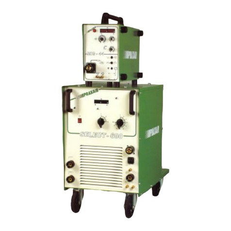
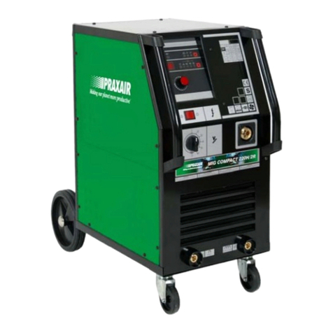
Praxair PHOENIX 401 BASIC PULS forceArc User manual

GB
Operating instructions
Machines for MIG/MAG and MMA welding
PHOENIX 401 BASIC PULS forceArc;
PHOENIX BASIC DRIVE 4 / 4L
N. B. These operating instructions must be read before commissioning.
Failure to do so may be dangerous.
Machines may only be operated by personnel who are familiar with the appropriate safety
regulations.
The machines bear the conformity mark and thus comply with the
• EC Low Voltage Directive (73/23/EEC)
• EC EMC Directive (89/336/EEC)
In compliance with IEC 60974, EN 60974, VDE 0544 the machines can be used in environments
with an increased electrical hazard.
© 2006 Subject to alteration. Item No.: 099-004838-PRA01 Dated: 10.04.06

Declaración de Conformidad CE
EU - Conformity declaration
Déclaration de Comformidité UE
Declaraçao de Conformidade CE
Nombre del Fabricante: PRAXAIR SOLDADURA, S.L.
Name of manufacturer: C/ Orense, 11 - 9ª planta
Nom du fabricant: 28020 MADRID
Nome do fabricante:
Dirección del Fabricante:
Address of manufacturer:
Adresse du fabricant:
Direcçao do fabricante:
Por la presente declaramos
que el diseño y la
construcción de la/s
máquina/s indicada/s
cumple/n las directivas funda-
mentales de seguridad para
bajo voltaje de la UE. Esta
declaración no tendrá validez,
en el caso de cambios no
autorizados, reparaciones ina
decuadas o modificaciones
que no hayan sido expresa
mente aprobadas por
PRAXAIR SOLDADURA, S.L.
We herewith declare that the
machine described below
meets the standard safety
regulations of the EU - low
voltage guideline in its
conception and construction,
as well as in the design put
into circulation by us, in case
of unauthorized changes
improper repairs and/or
modifications, which have not
been expressly allowed by
PRAXAIR SOLDADURA, S.L.
This declaration will lose its
validity.
Par la présente, nous déclarons
que la conception et la
construction ainsi que le modéle,
mis sur le marcha par bous, de
l'appareil decrit ci dessous
correspondent aux directives
fondamentales de securité de la
UE regissant les basses tensions.
En cas de chargements non
autorisés, de reparations
inadiquates et/ou de modifications
prohibeés, qui n'ont pas été
autorisés expressement par
PRAXAIR SOLDADURA, S.L.
cette declaration devient caduque.
Pela presente declaramos que
o desenho e a construçao
da(s) máquina(s) indicada(s),
cumprem as directivas
fundamentais de segurança
para vaisa voltagem da UE.
Esta declaraçao nâo terá
validade, no caso de trocas
nâo autorizadas, reparaçôes
inadequadas ou modificaçôes
que nâo tenham sido
aprovadas pela PRAXAIR
SOLDADURA, S.L.
Descripción de la máquina
:
Description of the machine:
Déscription de la machine:
Descriçao da máquina:
Tipo de máquina:
Type of machine
Type de machine
Tipo da máquina:
Número de Código:
Article number:
Numero d'article:
Número de Código:
Número de Serie:
Serial number:
Numéro de série:
Número de série:
Normas aplicadas:
Used co-ordinated norms:
Normes harmonisées appliquées:
Normas aplicadas:
EN 60974 - 1 / IEC 60974 – 1 / VDE 0544
73/23/CE
89/336/CE
Firma del Fabricante:
Signature of manufacturer:
Signature du fabricant:
Assinatura do fabricante:
Director de Producción
Production Manager
Directeur de Production
Director de Produçao

Estimado Cliente,
¡Enhorabuena! Usted acaba de elegir un producto de calidad de PRAXAIR
SOLDADURA.
Con los equipos de PRAXAIR se consiguen unos resultados de la máxima perfección,
gracias a su calidad SUPERIOR.
¡Nosotros desarrollamos y producimos calidad! Desde los componentes individuales
hasta el producto final, conservamos la exclusiva responsabilidad sobre nuestros
equipos.
Todos los componentes de nuestros equipos de soldar incorporan una tecnología
puntera del máximo nivel de calidad. Cada uno de nuestros productos es
cuidadosamente comprobado para poder garantizar unos materiales y productos libres
de defectos.
Estas instrucciones de funcionamiento contienen todo lo necesario para la puesta en
funcionamiento del equipo, notas de seguridad, mantenimiento y cuidado, datos
técnicos. Rogamos presten especial atención a las mismas para así asegurar unos
largos años de trabajo con el equipo en las mejores condiciones de seguridad.
Les agradecemos la confianza depositada en nosotros, y quisiéramos expresarles
nuestra gran ilusión de mantener con ustedes una relación a largo plazo en el espíritu
de “UNA VEZ PRAXAIR – SIEMPRE PRAXAIR”.
Un cordial saludo,
PRAXAIR SOLDADURA,S.L.

Datos del Equipo y de la Empresa
Rogamos introduzca los datos del equipo PRAXAIR así como los de su empresa en los campos
correspondientes
CE
TYP:
ART:
SNR:
PROJ:
GEPRÜFT/CONTROL:
Nombre de Cliente / Compañía
Dirección
Código postal / Ciudad
País
Sello / Firma distribuidor PRAXAIR
Fecha de compra
Nombre de Cliente / Compañía
Dirección
Código postal / Ciudad
País
Sello / Firma distribuidor PRAXAIR
Fecha de compra

Contents
PHOENIX 401 BASIC PULS forceArc
Item No.: 099-004838-PRA01 5
1Contents
1Contents..................................................................................................................................................5
2Safety instructions.................................................................................................................................7
3Technical data ......................................................................................................................................10
3.1 PHOENIX 401 BASIC PULS forceArc.........................................................................................10
3.2 PHOENIX BASIC DRIVE 4 / 4L...................................................................................................11
4Machine description ............................................................................................................................12
4.1 PHOENIX 401 BASIC PULS forceArc.........................................................................................12
4.1.1 Front view.....................................................................................................................12
4.1.2 Rear view......................................................................................................................14
4.2 PHOENIX BASIC DRIVE 4L........................................................................................................16
4.2.1 Front view.....................................................................................................................16
4.2.2 Rear view......................................................................................................................18
5Functional characteristics...................................................................................................................20
5.1 Machine control – Operating elements........................................................................................20
5.1.1 Wire feed machine control............................................................................................20
5.1.1.1 Covered operating elements.........................................................................22
5.1.1.2 JOB list..........................................................................................................24
5.1.2 Operating elements in the machine..............................................................................25
5.2 MIG/MAG welding........................................................................................................................26
5.2.1 Definition of MIG/MAG welding tasks...........................................................................26
5.2.2 Selecting MIG/MAG welding tasks...............................................................................26
5.2.2.1 Basic welding parameters.............................................................................26
5.2.2.2 Operating mode ............................................................................................26
5.2.2.3 Welding type .................................................................................................26
5.2.2.4 Choke effect / dynamics................................................................................27
5.2.2.5 Superpulses..................................................................................................27
5.2.2.6 Wire burn-back..............................................................................................27
5.2.3 MIG/MAG functional sequences / operating modes.....................................................28
5.2.3.1 Explanation of signs and functions ...............................................................28
5.2.3.2 Non-latched mode.........................................................................................29
5.2.3.3 Non-latched operation with superpulse.........................................................30
5.2.3.4 Special, non-latched......................................................................................31
5.2.3.5 Spots.............................................................................................................32
5.2.3.6 Special, non-latched with superpulse ...........................................................33
5.2.3.7 Latched mode ...............................................................................................34
5.2.3.8 Latched mode with superpulse.....................................................................35
5.2.3.9 Latched special.............................................................................................36
5.2.3.10 Special, latched with superpulse.................................................................37
5.2.4 MIG/MAG automatic cut-out.........................................................................................38
5.2.5 Standard MIG/MAG torch.............................................................................................38
5.2.6 Special parameter, “DRIVE 4 P wire feed units”..........................................................39
5.2.6.1 Special parameters list..................................................................................39
5.2.6.2 Selecting, changing and saving parameters.................................................39
5.2.6.3 Reset to factory settings ...............................................................................40
5.2.6.4 Ramp time for wire creep (P1)......................................................................40
5.2.6.5 Program "0", releasing the program block (P2) ............................................40
5.2.6.6 Display mode torch power control (P3).........................................................40
5.2.6.7 Program limit (P4).........................................................................................40
5.2.6.8 Special cycle in the operating modes special latched and non-latched
(P5).....................................................................................................................40
5.2.6.9 Enabling special JOBs SP1 to SP3 (P6).......................................................40
5.2.6.10 Correction operation, threshold value setting (P7) .....................................41
5.2.6.11 Program changeover with standard torch (P8)...........................................42
5.2.7 Interfaces......................................................................................................................43
5.2.7.1 PC interfaces.................................................................................................43

Contents
PHOENIX 401 BASIC PULS forceArc
6 Item No.: 099-004838-PRA01
5.3 TIG welding..................................................................................................................................43
5.3.1 TIG arc ignition .............................................................................................................43
5.3.1.1 Liftarc.............................................................................................................43
5.3.2 TIG function sequences / operating modes..................................................................44
5.3.2.1 Explanation of signs and functions................................................................44
5.3.2.2 Non-latched mode.........................................................................................45
5.3.2.3 Special, non-latched......................................................................................45
5.3.2.4 Latched mode................................................................................................46
5.3.2.5 Latched special .............................................................................................47
5.3.3 TIG automatic cut-out...................................................................................................47
5.4 MMA welding................................................................................................................................48
5.4.1 Arcforcing......................................................................................................................48
5.4.2 Hotstart .........................................................................................................................48
5.4.3 Antistick.........................................................................................................................48
5.5 Remote control.............................................................................................................................49
5.5.1 R10 manual remote control ..........................................................................................49
5.6 Resetting JOBs (welding tasks) to the factory settings................................................................50
5.6.1 Resetting a single JOB.................................................................................................50
5.6.2 Resetting all JOBs ........................................................................................................50
6Commissioning.....................................................................................................................................51
6.1 General.........................................................................................................................................51
6.2 Area of application – proper usage..............................................................................................51
6.3 Installation....................................................................................................................................51
6.4 Mains connection .........................................................................................................................51
6.5 Machine cooling ...........................................................................................................................51
6.6 Workpiece lead, general ..............................................................................................................51
7Maintenance and care..........................................................................................................................52
7.1 General.........................................................................................................................................52
7.2 Cleaning.......................................................................................................................................52
7.3 Repetition Test conforming to E VDE 0544-207, conforming to the German Ordinance on
Operational Safety .......................................................................................................................52
7.3.1 Test intervals and scope...............................................................................................53
7.3.2 Documentation of the test.............................................................................................53
7.3.3 Visual inspection...........................................................................................................53
7.3.4 Measurement of protective conductor resistance.........................................................53
7.3.5 Measurement of insulation resistance..........................................................................54
7.3.6 Measuring the leakage current (protective conductor and contact current).................54
7.3.7 Measuring the open circuit voltage...............................................................................54
7.3.8 Function test of the welding machine ...........................................................................54
7.4 Repair Work .................................................................................................................................55
8Operating problems, causes and remedies.......................................................................................56
8.1 Error messages (power source)...................................................................................................56
9Accessories, options ...........................................................................................................................57
9.1 General accessories ....................................................................................................................57
9.2 Remote control / connection cable...............................................................................................57
9.3 Options.........................................................................................................................................57
9.4 Computer communication............................................................................................................57
9.5 Welding data documentation........................................................................................................57
10 Circuit diagrams...................................................................................................................................58
10.1 PHOENIX 401 BASIC PULS forceArc .........................................................................................58
10.2 PHOENIX BASIC DRIVE 4 / 4L...................................................................................................60

Safety instructions
PHOENIX 401 BASIC PULS forceArc
Item No.: 099-004838-PRA01 7
2Safety instructions

Safety instructions
PHOENIX 401 BASIC PULS forceArc
8 Item No.: 099-004838-PRA01

Safety instructions
PHOENIX 401 BASIC PULS forceArc
Item No.: 099-004838-PRA01 9

Technical data
PHOENIX 401 BASIC PULS forceArc
10 Item No.: 099-004838-PRA01
3Technical data
3.1 PHOENIX 401 BASIC PULS forceArc
PHOENIX 401 PULSE forceArc
Setting range: Welding current / voltage
TIG 5 A / 10.2 V – 400 A / 26.0 V
MMA 5 A / 20.2 V – 400 A / 36.0 V
MIG/MAG 5 A / 14.3 V – 400 A / 34.0 V
Duty cycle at 20°C 40°C
60% DC - A 400 A
80% DC 400 A - A
100% DC 370 A 360 A
Load alternation 10 min (60% DC ∧6 min welding, 4 min break)
Open circuit voltage 92 V
Mains voltage (tolerances) 3 x 400 V (-25% to +20%)
Frequency 50/60 Hz
Mains fuse (slow-blow safety fuse) 3 x 35 A
Mains connection lead H07RN-F4G4
Max. connected power 21.5 kVA
Recommended generator rating 29.0 kVA
Cosϕ/ efficiency 0.99 / 89%
Insulation class / protection classification H / IP 23
Ambient temperature -10°C to +40°C
Machine / torch cooling Fan / gas or water
Cooling capacity at 1 l/min 1200 W
Max. flow rate 5 l/min
Max. initial coolant pressure 3.5 bar
Max. tank capacity 7 l
Coolant Ex works: KF 23E (-10°C to +40°C) or
KF 37E (-20°C to +10°C)
Workpiece lead 70 mm2
Dimensions L/W/H [mm] 1100 x 455 x 950
Weight 111.5 Kg
Constructed to standards IEC 60974 / EN 60974 / VDE 0544
EN 50199 / VDE 0544 Part 206 / /

Technical data
PHOENIX BASIC DRIVE 4 / 4L
Item No.: 099-004838-PRA01 11
3.2 PHOENIX BASIC DRIVE 4 / 4L
PHOENIX DRIVE 4 DRIVE 4L
Supply voltage 42 VAC / 60 VDC
Max. welding current at 60% DC 500 A
Wire feed speed 0.5 m/min to 24 m/min
Standard WF roller fitting 1.0 + 1.2 mm (for steel wire)
Drive 4-roller (37 mm)
Torch connection Euro-central or Dinse-central
Protection classification IP 23
Ambient temperature -10°C to +40°C
Dimensions (LxWxH) [mm] 680 x 460 x 265 690 x 300 x 410
Weight incl. intermediate tube package 1.5 m approx. 24 kg approx. 20.5 kg
Constructed to standards IEC 60974 / EN 60974 / VDE 0544
EN 50199 / VDE 0544 Part 206 /

Machine description
PHOENIX 401 BASIC PULS forceArc
12 Item No.: 099-004838-PRA01
4Machine description
4.1 PHOENIX 401 BASIC PULS forceArc
4.1.1 Front view
Figure 4-1

Machine description
PHOENIX 401 BASIC PULS forceArc
Item No.: 099-004838-PRA01 13
Item Symbol Description 0
1 Wire feed unit
2 Lifting lug
3 Carrying handle
4
Main switch, machine on/off
5 Cooling air inlet
6
“Automatic cut-out of coolant pump” key button
(press to reset a triggered fuse)
7 Conveyor rolls, guide castors
8 Coolant tank
9 Coolant tank cap
Connection socket, “-” welding current
• MIG/MAG welding: Workpiece connection
• MMA welding: Workpiece or electrode holder connection
10
• TIG welding: Welding current connection for welding torch
Connection socket, “+” welding current
• MMA welding: Workpiece or electrode holder connection
11 • TIG welding: Workpiece connection
12 Control / Operating elements (see chapter Function specification)

Machine description
PHOENIX 401 BASIC PULS forceArc
14 Item No.: 099-004838-PRA01
4.1.2 Rear view
The maximum possible machine configuration is given in the text description.
If necessary, the optional connection may need to be retrofitted (see "Accessories" chapter).
Figure 4-2

Machine description
PHOENIX 401 BASIC PULS forceArc
Item No.: 099-004838-PRA01 15
Item Symbol Description 0
1 Lifting lug
2
42V/4A
"Automatic cutout" key button
Wire feed motor supply voltage fuse
(press to reset a triggered fuse)
3
19-pole connection socket (analogue)
Wire feed unit control lead connection
4
PC INT
PC interface, serial (D-SUB connection socket, 9-pole)
5 Connector plug, welding current "+"
Welding current connection on wire feed unit
6
Connection socket, “-” welding current
• MIG/MAG welding: Workpiece connection
• MIG/MAG cored wire welding: Welding current connection on wire feed unit
7 Coolant return from the DV device (red rapid-action closure coupling)
8 Coolant water supply to the DV device (blue rapid-action closure coupling)
9 Conveyor rolls, fixed castors
10 Cooling air outlet
11
analog
Automation interface, 19-pole (analogue)
(see Function Specification chapter)
12 Safety chain
13 Strain relief with mains connection cable
14 Cylinder bracket

Machine description
PHOENIX BASIC DRIVE 4L
16 Item No.: 099-004838-PRA01
4.2 PHOENIX BASIC DRIVE 4L
4.2.1 Front view
Figure 4-3

Machine description
PHOENIX BASIC DRIVE 4L
Item No.: 099-004838-PRA01 17
Item Symbol Description 0
1 Slide latch, lock for the protective cap
2 Label "Wire feed parts subject to wear"
3 "JOB list" sticker
4 Cover for wire delivery unit and operating elements
5 Carrying handle with integrated lifting lug
6 Wire spool casing
7 Control / Operating elements (see chapter Function specification)
8 Spool holder
9 Wire delivery unit
10
Euro-central connector (welding torch connection)
Welding current, shielding gas and torch trigger included
11 Control / Operating elements (see chapter Function specification)
12
Changeover switch, remote control on/off
13 19-pole connection socket (analogue)
For connecting analogue remote controls
14 Rapid-action closure coupling, blue (coolant supply)
15 Rapid-action closure coupling, red (coolant return)

Machine description
PHOENIX BASIC DRIVE 4L
18 Item No.: 099-004838-PRA01
4.2.2 Rear view
Figure 4-4

Machine description
PHOENIX BASIC DRIVE 4L
Item No.: 099-004838-PRA01 19
Item Symbol Description 0
1 Intermediate tube package strain relief
2
19-pole connection socket (analogue)
Wire feed unit control lead connection
3
Connecting nipple G¼, shielding gas connection
4 Rapid-action closure coupling, red (coolant return)
5 Rapid-action closure coupling, blue (coolant supply)
6 Connector plug, welding current "+"
Welding current connection on wire feed unit

Functional characteristics
Machine control – Operating elements
20 Item No.: 099-004838-PRA01
5Functional characteristics
5.1 Machine control – Operating elements
5.1.1 Wire feed machine control
Figure 5-1
Item Symbol Description 0
“Parameter selection ” (left)
AMP
Welding current (nominal, actual and hold values)
Material thickness (nominal value)
Wire speed (actual, nominal and hold values)
1
HOLD
AMP
HOLD
After each completed welding process, the last parameter values
used for the welding process are shown on the display in the main
program; the signal light is on
2 LCD display, 3-digit (left)
Display of the parameters and values: Welding current, material thickness, wire speed,
hold values
3
m/min
"Wire speed / welding parameter setting" rotary dial
Infinitely adjustable setting of the wire speed from 0.5m/min to 24m/min
(welding performance, one-dial operation)
"Select operating mode" button
Non-latched
Latched
Non-latched special (LED green) / MIG spots (LED red)
4
Special latched
This manual suits for next models
2
Table of contents
Other Praxair Welding System manuals
Popular Welding System manuals by other brands

GÜDE
GÜDE GPS-E 40 A Translation of the original instructions

ESAB
ESAB Railtrac BV2000 instruction manual

Motor Guard
Motor Guard Magna-Spot JO1000 instruction manual

ASKAYNAK
ASKAYNAK Plasma 45 ULTRA user manual

Thermal Arc
Thermal Arc 400S Service manual

Ritmo
Ritmo MUSTANG 160 V1 Use and maintenance handbook

Top Gun
Top Gun 205 LCD Manual guide

Miller
Miller Gold SealTM Model 5000 owner's manual

SifWeld
SifWeld Evolution TS200DC Operation manual

Lincoln Electric
Lincoln Electric POWER WAVE 655/R Service manual

ADN
ADN WEIRO SUPERTIG315EX Operation instructions

Lincoln Electric
Lincoln Electric Square Wave TIG 200 Operator's manual