伺服產品/Servo Products
–
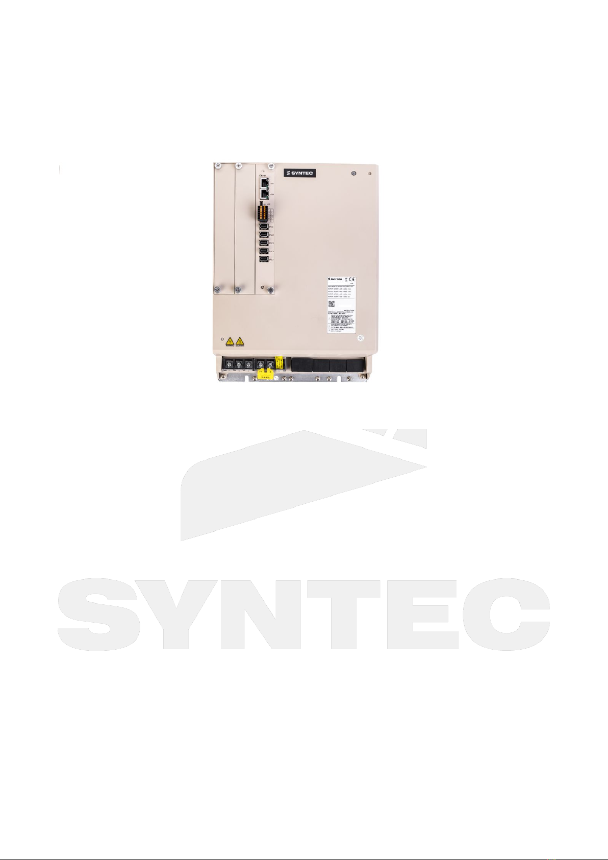
Hardware Manual of SMH-25/25/35-75-XL (Encoder : 5 Ports)
Handling and installation–10
•
•
•
•
•
•
•
•
•
•
•
•
•
•
•
•
•
•
•
4 Handling and installation
4.1 Transportation
The entire body of the drive must be held during transportation. To avoid the risk of falling, do NOT hold the drive
by its upper cover or by any individual part.
4.2 Installation Environment Conditions and Precautions
Installation Environment Conditions
Locations without high heat generating devices.
Locations without floating dust or metal particles.
Locations without corrosive or flammable gasses and liquids.
Locations without water, steam, dust, or oily dust.
Locations without electromagnetic noise interference.
A sturdy, vibration-free location.
Suitable ambient temperature is 0 ° C ~ 55 ° C; if the ambient temperature is above 45 ° C, please put the
drive in a well-ventilated place or in an air-conditioned room.
Installation Precautions
Install the drive in the direction specified bythe instructions; incorrect positioning may lead to servo failure.
When installing the drive, do not block its ventilation holes and do not place it upside down, otherwise the
drive may malfunction.
Do not use on or near flammable materials.
Make sure that each fastening point is tight when fixing the drive in place.
Install on a surface that can withstandthe weight.
Operation Precautions
For long-term operation, it is recommended to maintain an ambienttemperaturebelow 45 °C to ensure
product reliability.
If the product is installed inanelectrical cabinet, the size and ventilation of thecabinetmust prevent any
internal electronic devices from overheating. Also pay attention to whether the machine's vibrations will
affect other electronics in the cabinet.
To enhancecooling circulation, maintain sufficient space between all sides and surrounding objects of the
drive and the baffles (walls); also take care not to block the ventilation holes, otherwise the drive may
malfunction.
Other Precautions
The cable between the drive and the motor should not be stretched too tightly.
Do not place heavy objects on top of the drive.
Keep the drive clear from conductive objects such as metal and screws or combustibles such as oil.
If the cable connecting the motor and the drive is longer than 20 meters, please thicken the U, V, W and
encoder cables.