Syris SY210NT V5 User manual

1
SY210NT V5
Networking Muti-Doors Controller
Installation Manual
V0110
WARNING: This manual contains information on limitations
regarding product use and function and information on the
limitations as to liability of the manufacturer. The entire manual
should be carefully read.
SYRIS Technology Corp. 21F-2, NO.12, Sec1, Taijunggang Rd, Taichung , Taiwan (403)
Tel:+886-4-2207-8888 Fax:+886-4-2207-9999 Email:[email protected]et

2
SECTION 1: INTRODUCTION TO SY210NT V54
1.1 PRODUCT OVERVIEW ..............................4
1.2 ABOUT THIS MANUAL ..............................4
1.2.1 New in this Version ..............................4
1.2.2 Fast Setting Index Sheet and Card Record Sheet
4
1.3 FEATURES..............................................4
1.4 SPECIFICATIONS .....................................4
SECTION 2: SY210NT WIRE & QUICK INSTALLING
...........................................................................5
2.1 REQUIRED EQUIPMENT ............................5
2.2 SELECTING A MOUNTING LOCATION ..........5
2.3 TYPICAL MOUNTING DIAGRAM..................5
2.4 INSTALLING SY210NT ............................5
2.5 INSTALLING THE READER WIRING DIAGRAM5
2.6 CONNECTING DOOR LOCK WIRING DIAGRAM 5
2.7 CONNECTING BUTTON TO DOOR OPEN ......5
2.8 CONNECTING THE DOOR DETECTION .........5
2.9 CONNECTING POWER SUPPLY ...................5
SECTION 3: SY210NT V5 SETTING INTRODUCTION
...........................................................................6
3.1 SETTING MENU LOGIN.............................6
3.2 SETTING MENU LOGOUT..........................6
3.3 SHOW VERSION ......................................6
3.4 SY210NT FACTORY DEFAULTS ...............6
SECTION 4: SY210NT V5 SETTINGS .............6
4.1 SYSTEM FUNCTIONS................................6
4.1.1 Controller Functions ............................6
4.1.2 Module...................................................6
4.1.3 Door .......................................................6
4.1.4 Master....................................................6
4.1.5 System Utility........................................6
4.2 CARD MANAGEMENT ...............................7
4.2.1 Add Card ...............................................7
4.2.2 Edit Card ...............................................7
4.2.3 Delete Card ...........................................7
4.2.4 Show Card.............................................7
4.2.5 All Card APB Setting ............................7
4.3 FINGERPRINT MANAGEMENT .................... 7
4.3.1 Add Fingerprint .................................... 7
4.3.2 Delete Fingerprint ................................ 7
4.3.3 Delete All Fingerprint........................... 7
SECTION 5: SET UP SY210NT V5 STEP BY STEP
.......................................................................... 7
5.1 CONTROLLER FUNCTION ................................. 7
5.1.1 Set Controller ID................................... 7
5.1.2 Same Card Time................................... 7
5.1.3 Invalid Password Lock ........................ 7
5.1.4 Baud Rate Setting ................................ 7
5.1.5 DI Setting .............................................. 7
5.1.6 Elevator Mode ...................................... 7
5.1.7 Set Controller Max Card ...................... 7
5.2 READER MODULE SETTING...................... 7
5.2.1 Module Auto Detect ............................. 8
5.2.2 Reader Module ID Setting ................... 8
5.2.3 MDWIE-2 ID Setting.............................. 8
5.3 DOOR FUNCTION SETTING ....................... 8
5.3.1 Door Relay ............................................ 8
5.3.2 Door Push Button ................................ 8
5.3.3 Door APB Setting................................. 8
5.4 MASTER CARD FUNCTION SETTING .......... 8
5.4.1 Master PIN Setting ............................... 8
5.4.2 Add Master Card .................................. 8
5.4.3 Delete Master Card .............................. 8
5.5 SYSTEM UTILITY ..................................... 8
5.5.1 Date Setting .......................................... 8
5.5.2 Time Setting ......................................... 8
5.5.3 System Reboot..................................... 8
5.5.4 Data Backup / Restore......................... 9
5.5.5 System Initial........................................ 9
5.6 CARD MANAGEMENT............................... 9
5.6.1 Add Card............................................... 9
5.6.1.1 Add Card By Serial ................................ 9
5.6.1.2 Add Card By No..................................... 9
5.6.2 Edit Card ............................................... 9
5.6.2.1 Card Condition Setting (Valid / Invalid)9
5.6.2.2 Card PIN Setting .................................. 9
5.6.2.3 Card APB Setting................................. 9

3
5.6.2.4 Single Card Delete ...............................9
5.6.2.5 Delete All Card......................................9
5.6.2.6 Cards Browse .......................................9
5.6.2.7 All Card APB Setting............................9
5.7 FINGERPRINT MANAGEMENT ..................10
5.7.1 Add Fingerprint .....................................10
5.7.2 Delete Fingerprint .................................10
5.7.3 Delete All Fingerprint ............................10
5.8 RESETTING THE SY210NT UNIT TO FACTORY
DEFAULTS..........................................................10
APPENDIX 1:QUICK REFERENCE PROGRAMMING TABLE
11
APPENDIX 2:PROGRAMMING WORKSHEET..........12
APPENDIX 3:CARD INFORMATION RECORD SHEET13
APPENDIX 4:SY210NT V5 CARD CAPACITY AND I/O DATA
LIST 14
APPENDIX 5:USING THE SY210NT SYSTEM.......15
Q1:How to setting reader ID? What Reader ID and are
Door relate? ........................................................15
Q2:How to add the card?...............................16
Q3:How to setting the push button from controller?
16
Q4:How to Connect HID Readers of Wiegand interface
with Controller? ..................................................17
Q5:How to use MDDIDO Module Connecting the Exit
Detector or Exit Button?...................................18
APPENDIX 6:GENERAL WIRING DIAGRAM .........20

4
Section 1: Introduction to SY210NT V5
1.1 Product Overview
Networking Multi-Doors Controller can control 4 doors, link 8 card readers (4 IN, 4
OUT), use 63,000 cards and 210,000 I/O data record at most. (Reference
appendix 4)
SY210NT V5 Network Multi-Doors Controller provides perfect functions and stable
& reliable quality.
* The controller can supply 63,000 people to use at most.
* Single controller can manage 4 doors In/Out at the same time.
* RegionalAnti-Pass Back (APB) function will be activated without PC on-line.
* The localAPB will be activated in LAN.
* The motherboard produced by the SMD technology. The quality is stable and
reliable.
Easy Setting
All setting can be set by using controller keypad and LCD monitor(16x2 Char).
You can make choice of purchase of expansion module that divides into two types:
internal and external.
Internal module of controller include:
1. MDNET-2 Ethernet Converter
Ethernet Communication Converter used to convert RS485 series signal
into TCP/IP package. According to different network application types, the
module provides two types:Server mode & Client mode.
The module will wait for the signal from network and it will send decode
signal to HOST CPU through series communication port under Server
mode. The module will re-package the signal and resend on network while
received reply from the CPU HOST. And then the command cycle will be
done.
User can add MDNET-2 network module to expand network function
interface.
2. MDPOE-1 Ethernet Power supplier module (Power over
Ethernet)
Power over Ethernet is called PoE that is the technology about power
supply. PoE can transmit electrical power over standard twisted-pair cable in
an Ethernet network. We can supply power from HUB by using this
technology without connect other power source.
3. MDWIE-2 (Wiegand Signal Input Module)
After installing 4 CH Wigand signal input module (MDWIE-2), user can
connect four readers that include reader、fingerprint …etc. All devices as
mention have Wiegand interface.
4. SD Card
User can choose the SD CARD module to increase IO records or backup
the controller data. The slot of SD CARD(MDSD-2) can compatible with the
capacity of SD CARD include 256MB、512MB and 1GB.
External Device of Controller:
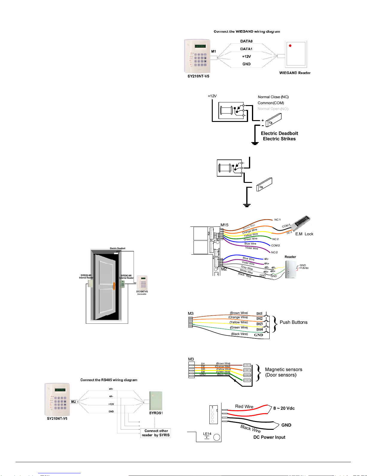
1. Reader
The Reader includes SYRDS1 Proximity Card Reader、SYRDS5 Proximity
Card Reader、SYRDL5 Mini Proximity Reader、SYRDT5 LCD Proximity
Card Reader and SYRDF5/F6 Fingerprint Reader.
System extendibility:Link 8 readers atmost. The types of Reader divide into
125K (EM)、13.56M (Mifare).
2. MDDIDO Module
MDDIDO Module divides MDDIDO-16 channel (16 voltage free input, 16
relay output) and MDDIDO-1S 2 channel (4 voltage free input, 2 relay
output).
System extendibility:User can use MIDDO module expansion of system
when first program insufficient for user need; MDDIDO Module is easy to
expansion; e.g. Add controller, Readers or DIDO Modules…etc.
3. MDWIE-1 (Wigand
Module install inside of the
Controller)
MDWIE-1 Wigand Module has 2 S/N. Each number represents a channel, is
similar to RS485 Reader; First W26Reader use first Serial NO. Reader ID
setting( ID=1, Firs door; ID=2;Second door…..). When expand the
MDWIE-1 Module to transform the RS485 interface into the Wiegand
interface, user can connect with each kind of devices of Wiegand interface.
MDNET-1 Module
The functions are same as MDNET-2.
4. Printer Module
Controller can connect to the following printers directly or reports printing via
printer module.
1. Impact Printers 2. Ink Jet Printer 3. Laser Printers
1.2 About this Manual
This Installation Manual provides installation and setting instructions for SY210NT
V5. Please read this manual carefully before installing or setting the SY210NT.
1.2.1 New in this Version
The subject matters of the manual are focus on update of SY210NT V5:
1.Increase the number of user:The number of user can up to 63,000. I/O records
can up to 21,000. (Reference appendix 4)
2.The time of door open by hand is longer:The time can be set as 9999 seconds or
above.
3.Backup SD Card:The types of backup are Manual /Automatic. The backup /
restore set can up to 10 sets.
4. Invalid password entering event handle:User can set times or lock time while
error password input (1~999 sec).
1.2.2 Fast Setting Index Sheet and Card Record Sheet
User can find outa setting location by referring the “Quick Reference Programming
Table”, appendix 1.
User can print and record Card Information by using appendix 3..
1.3 Features
1. Internal extension Module optional:
(a) 10/100M Ethernet Converter(MDNET-2).
(b) 4CH Wigand Signal Input Module(MDWIE-2).
(c) SD Card module (MDSD-2 applies SD Card whose memory size of
256MB、512MB、1GB).
(d) POE Power over Ethernet Module (MDPOE-1,Client).
2. The controller canbe run with the software: SYW95A-V832.11、V2、V3、SYW95A
-V2-NET and SY-SOFT-95A.
3. User can adjust the number of cards and record capacity of I/O data according to
need.
4. Promote number of User/Card and I/O data record:If using the new version of
SY-SOFT-95A, the card/user capacity can increase to 21,000; High-capacity
Device can promote number of User/Card to 63,000 and promote I/O data records
to 210,000 at most. The whole speed of CPU promotes to 100 MIPS. (Reference
appendix 4).
5. After installing SD Card Module and SD Card, user can backup all data from the
controller.
6. Fast update firmware:Support to update the firmware on-line through RS485 or
Ethernet.
7. While Ethernet network module is added, the communication styles to HOST-PC
are polling and auto-transmission. Both of the polling and auto-transmission can
run at the same time. The system provides not only efficient transmission but also
response event immediately. While more and more doors in system, the excellent
functions will be presented.
8. The system will send commands to related controller and modules to active fire
control and fire alarm automatically through Ethernet converter. The functions also
can be handled through client PC.
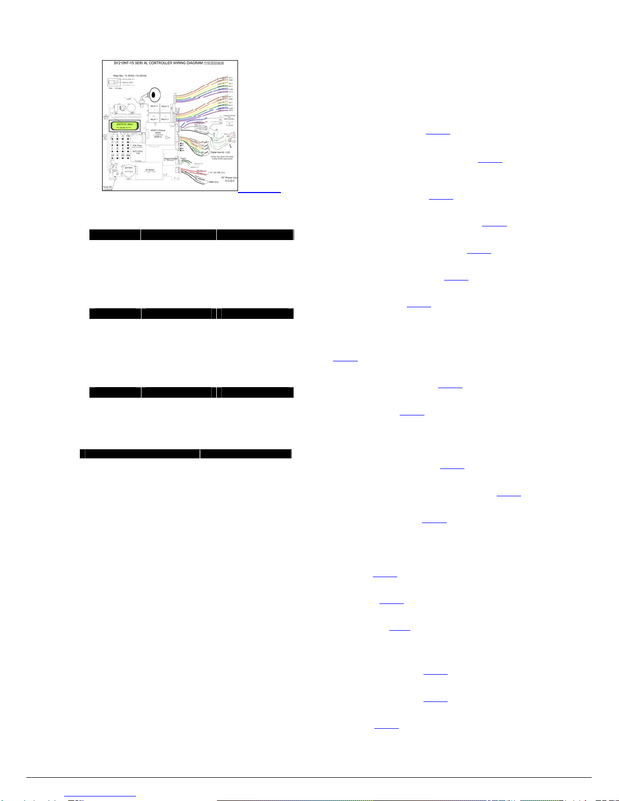
1.4 Specifications
Number of Cards—3,500 ~ 63,000;
Number of Readers— 8 (4 IN, 4 OUT);
I/O Records—21,000~3500 (Reference appendix 4);
Control Doors— 4 Door;
Output— 4 relay;
Input— 8 points;
LCD Display— 16 ×2 LCD;
Indicator— 8 LED;
Reader Technology— SYRIS RS485 format;
User PIN— 4 digital codes;
Communication ports— RS485 ×2,Optional 10M/100M Ethernet; / 802.11b
WiFi
Baud Rate— Default 19,200bps, 4,800、9,600、19,200、38,400、57,600、115,200、

5
230,400、460,800、921,600、1,843,200 (Over 115,200 , must use MDNET-2);
Controller ID — 0001- 9999 & 01- 99;
Holidays — 366 days;
Expand Reader & Module — SYRIS series module;
Anti Pass-Back — Level 3 or GroupAnti Pass-Back;
Speaker Output — Built-in (max 0.2W);
Time Zone — 60 time zones;
Timer — 0-32 Timer;
Group (Application set) — 64 Application Set;
Software — SY-SOFT-95A / SYW95A-NET-V2 / SYW95A-V3 & V2 & V832.11;
Keypad —16key keypad;
Humidity —10% to 95% (Non-condensing);
Operating Temperature —--20℃to 70℃;
Power Supply — 8V to 24V DC / 0.3W to 3W;
Dimensions(mm) — 135W ×175H ×45D (Controller) / 122W ×117H ×25D
(Control Board);
Ethernet TCP/IP Module — Optional MDNET-2;
SD Card Module — Optional MDNSD-2 & SD Card 256M、512M、1G;
Wiegand Module — Optional MDWIE-2;
Power Supply Module Over Ethernet — Optional MDPOE-1;
Section 2: SY210NT Wire & Quick Installing
2.1 Required Equipment
Power supply —12V / DC(required);
Controller and Reader connection — RS485 twisted pairs;
Controller and Computer connection — SYLINK-F via USB or RS232;
Relay connection — Relay connects with electromagnetic lock.
2.2 Selecting a Mounting Location
Select a mounting location for the unit using the following guidelines:
zNext to the door that is being supervised;
zTo avoid setting controller in huge noise areas;
zIt is recommended that setting up location should be visible for flashing card to access
easily. The height of setting location should between 45 to 50 inches to the floor.
2.3 Typical Mounting Diagram
2.4 Installing SY210NT
1. Separate the controller and its back panel by pulling the upper side;
2. Use the back panel to mark the screw holes position on the wall;
3. Screw back panel on the wall by using four (4) screws (provided);
4. Put back controller to the back panel;
2.5 Installing the Reader Wiring Diagram
2.6 Connecting Door Lock Wiring Diagram
Door Open by power supply failure wiring diagram
Common(COM)
Normal Close (NC)
Normal Open (NO)
+
-
+12V
Electric Deadbolt
Electric Strikes
Door Open by start power supply wiring diagram
Electronic Lock wiring diagram
2.7 Connecting button to Door Open
2.8 Connecting the Door detection
2.9 Connecting power supply
GNDGND+V+VM5
2.1

6
2.10 General Wiring Diagram
〈Enlarge〉
Section 3: SY210NT V5 Setting Introduction
3.1 Setting Menu Login
Keypad LCD display Annotation
MENU Login
EN Password
﹝_ _ _ _ _ _﹞Using numeric keypad
input password.
EN Master
Ok Login success.
3.2 Setting Menu Logout
Keypad LCD display Annotation
MENU Login
▲▼ or MENU Logout Using ▲▼ choice to
logout.
EN yyyy/mm/dd (Thu)
hh:mm:ss Show time expresses
successfully.
3.3 Show Version
Keypad LCD display Annotation
MENU Login
▲▼or MENU SY210NT4V5.07-01
S/N:XXXXXXXX Using ▲▼ choice to
version information.
3.4 SY210NT Factory Defaults
Description Factory Default
Login Password 1234
Controller ID ID:[0001]
Controller Same card [0000] sec
Controller PIN lock [3] 次
Lock time [060]sec
Controller Comm. Baud rate 19200.e.8.1 [4A]
19200.e.8.1 [4R]
Controller Elevator mode [NO]
Controller Max card 10500
Door Relay ID:[1~4] CH:[1~4]
Times 05 sec
Door Push button No
Door APB setting [0]
System Utility Backup 60 Day(Optional
MDNSD-2 & SD Card)
Section 4: SY210NT V5 Settings
4.1 System Functions
4.1.1 Controller Functions
Controller ID
Set Controller ID when Controllers are serious connection (EX:First controller ID:
0001 ; Second controller ID:0002). <Setting>
SameCardTime
The period means flashing one card twice or continuous. <Setting>
InvalidPasswordLock
While user input invalid password over setting times, the system will lock down.
User can't input when system lucked. <Setting>
Comm. Baud rate
Communication Baud rate (4A/4R). Default is 19200.e.8.1. <Setting>
DISetting
The NO/NC settings of DI are in control and module. <Setting>
ElevatorMode
Enable elevator function to control elevator. <Setting>
CardVolume
Set the max number of card. <Setting>
4.1.2 Module
Auto Detect Module
The system will search new added module by setting the function enabled.
<Setting>
Module ID Setting
Set up module ID by input serial number. <Setting>
MDWIE-2 ID Setting
Set up reader channel ID .<Setting>
4.1.3 Door
Door Relay
Set up the parameters of door open relay. <Setting>
PushButton(DoorOpen)
Set up the parameters of push button that is used for door open. <Setting>
Door APB Setting
Set up the level of Door APB (0~3).<Setting>
4.1.4 Master
Master Password Setting
Master Password Setting. Change password in unpredictable period is
recommended. <Setting>
Add Master Card
Add Master Card. <Setting>
DeleteMasterCard
Delete Master Card. <Setting>
4.1.5 System Utility
DateSetting
Set date according to user request. <Setting>
TimeSetting
Set time according to user request. <Setting>
SystemReboot
Reboot system. <Setting>
DataBackup/Restore

7
Backup/Restore data to system (SD Card required). <Setting>
System Initial
Set system to default factory setting. <Setting>
4.2 Card Management
4.2.1 Add Card
AutoAddCardBySerial
Add the card automatically by serial (flash card continuously). <Setting>
Add Card By Card No.
Add the card by card number.(Set card ID first then flash card) <Setting>
4.2.2 Edit Card
EditCardStatus
Set the card as enabled or disabled. <Setting>
EditCardPIN
Edit the card PIN (4 digital codes). <Setting>
EditCardAPB
Set APB of card as enabled or disabled. <Setting>
4.2.3 Delete Card
Delete Card by Card Number
Delete car by card number. <Setting>
DeleteAllCards<Setting>
Delete all cards in controller.
4.2.4 Show Card
After flashing the card, system will show card information. <Setting>
4.2.5 All Card APB Setting
All card APB condition setting. <Setting>
4.3 Fingerprint Management
4.3.1 Add Fingerprint
Add fingerprint. <Setting>
4.3.2 Delete Fingerprint
Delete single fingerprint. <Setting>
4.3.3 Delete All Fingerprint
Delete all fingerprints. <Setting>
Section 5: Set up SY210NT V5 Step by Step
5.1 Controller Function
Keypad LCD display Annotation
MENU Login
EN Password
[ _ _ _ _ _ _ _ ] Using numeric keypad
input password
EN Master
Ok Login success
▲▼or MENU System
EN Controller
5.1.1 Set Controller ID
System →Controller
Keypad LCD display Annotation
EN Controller
ID
EN Controller ID
﹝0001﹞Using numeric keypad
input ID.
5.1.2 Same Card Time
System →Controller
Keypad LCD display Annotation
▲▼or MENU Controller
Same card time
EN Same card time
﹝000﹞sec Using numeric keypad
input setting value.
5.1.3 Invalid Password Lock
System →Controller
Keypad LCD display Annotation
▲▼or MENU Controller
PIN lock
EN Error number
[3] Using numeric keypad
input setting value.
EN Lock time
[060] sec Using numeric keypad
input setting value.
5.1.4 Baud Rate Setting
System →Controller
Keypad LCD display Annotation
▲▼or MENU Controller
Comm. Baud rate
EN Baud rate(4A)
[19200,e,8,1] Using ▲▼ choice rate,
EN Baud rate(4R)
[19200,e,8,1] Using ▲▼ choice rate,
5.1.5 DI Setting
System →Controller
Keypad LCD display Annotation
▲▼or MENU Controller
DI Setting
EN ID
[ 0 ] ID:0 is controller
ID:1-8 is MDDIDO
EN DI setting
NO/NC:[0-0-0-0] Using numeric keypad
input setting value.
0=NO , 1=NC
5.1.6 Elevator Mode
System →Controller
Keypad LCD display Annotation
▲▼or MENU Controller
Elevator mode
EN Elevator mode
[ No ] Using ▲▼ choice YES /
NO.
5.1.7 Set Controller Max Card
System →Controller
Keypad LCD display Annotation
▲▼or MENU Controller
Max card
EN Max card
[ 10500 ] Using numeric keypad
input setting value.
EN Record clear!
[ No ]
Using ▲▼ choice YES /
NO (Chooses YES only
then to be able to change
the setting value).
EN Card:[ 10500 ]
Record:[ 14000 ] Card:Max card number
Record:Max I/O data.
NOTE:If the user determines the change controller max card, then must first the data
backup. After Record clear! [YES], IO data completely will delete
5.2 Reader Module Setting
Keypad LCD display Annotation
MENU Login
EN Password
[ _ _ _ _ _ _ _ ] Using numeric keypad
input password.
EN Master
Ok Login success.
▲▼or MENU System
EN Module

8
5.2.1 Module Auto Detect
System →Module
Keypad LCD display Annotation
▲▼or MENU Module
Auto detect
EN Auto detect
Waiting……. Controller auto detect
display.
Find module:[ 02 ]
Ok! Found two modules.
5.2.2 Reader Module ID Setting
System →Module
Keypad LCD display Annotation
▲▼or MENU Module
ID setting
EN ID setting
[ SYRDS1/S5/L5 ] Using ▲▼ choice
module.
EN S/N
[ _ _ _ _ _ _ _ _ _ ] Using numeric keypad
input serial number.
EN Module ID
[ 0 ] Using numeric keypad
input module ID.
5.2.3 MDWIE-2 ID Setting
System →Module
Keypad LCD display Annotation
▲▼or MENU MDWIE-2
ID setting
EN MDWIE-2
CH-ID [ 1-2-3-4 ]
Using ▲▼ choice
Reader Channel ID and
Using numeric keypad
input Channel ID .
EN MDWIE-2
ID setting .
5.3 Door Function Setting
Keypad LCD display Annotation
MENU Login
EN Password
[ _ _ _ _ _ _ _ ] Using numeric keypad
input password.
EN Master
Ok Login success.
▲▼or MENU System
EN Door
EN Door
No :[ 1 ] Using numeric keypad
setting door.
5.3.1 Door Relay
System →Door →Door [ 1~4 ]
Keypad LCD display Annotation
▲▼or MENU Door
Relay
EN Relay
ID:[ 0 ] CH:[ 01 ] Using numeric keypad
input ID and CH.
EN Time
[ 005 ] sec Using numeric keypad
input time.
5.3.2 Door Push Button
System →Door →Door [ 1~4 ]
Keypad LCD display Annotation
▲▼or MENU Door
Push button
EN Push button
ID:[ 0 ] CH:[ 01 ] Using numeric keypad
input ID and CH.
5.3.3 Door APB Setting
System →Door →Door [ 1~4 ]
Keypad LCD display Annotation
▲▼or MENU Door
APB setting
EN APB setting
Level:[ 0 ] Using numeric keypad
setting level 0~3.
5.4 Master Card Function Setting
Keypad LCD display Annotation
MENU Login
EN Password
[ _ _ _ _ _ _ _ ] Using numeric keypad
input password.
EN Master
Ok Login success.
▲▼or MENU Master
5.4.1 Master PIN Setting
System →Master
按鍵 顯示畫面 備註
▲▼or MENU Master
PIN setting
EN Master
No:[ 1 ] Using numeric keypad
input number (1-3).
EN PIN setting
[ _ _ _ _ _ _ _ ] Using numeric keypad
input password.
5.4.2 Add Master Card
System →Master
Keypad LCD display Annotation
▲▼or MENU Master
Add card
EN Master
No:[ 1 ] Using numeric keypad
input number (1-3).
EN Master
Punch card Please punch the card.
5.4.3 Delete Master Card
System →Master
Keypad LCD display Annotation
▲▼or MENU Master
Delete card
EN Master
No:[ 1 ] Using numeric keypad
input number (1-3).
5.5 System Utility
Keypad LCD display Annotation
MENU Login
EN Password
[ _ _ _ _ _ _ _ ] Using numeric keypad
input password.
EN Master
Ok Login success.
▲▼or MENU System
EN System utility
5.5.1 Date Setting
System →System utility
Keypad LCD display Annotation
▲▼or MENU System utility
Date setting
EN Date setting
[ 07 / 08 / 15 ] Using numeric keypad
setting date. (YY/MM/DD).
5.5.2 Time Setting
System →System utility
按鍵 顯示畫面 備註
▲▼or MENU System utility
Time setting
EN Time setting
[15:00:37 ] Using numeric keypad
setting time .(hh:mm:ss)
5.5.3 System Reboot
System →System utility
Keypad LCD display Annotation
▲▼or MENU System utility
Reboot

9
EN System Reboot
[ No ] Using ▲▼ choice YES /
NO.
5.5.4 Data Backup / Restore
System →System utility (The use in optional SD Card Module)
Uses the SD card backup data
Keypad LCD display Annotation
▲▼or MENU System utility
Backup / Restore
EN Backup / Restore
[ Manual Backup ] Using ▲▼ choice
Backup or Restore .
EN 2007/06/22 16:19
[ YES ] Using ▲▼ choice YES /
NO.
EN Manual backup
[ Waiting… xxxx ] Start a backup display.
Manual backup
Ok Backup success.
Uses the SD card restore data
Keypad LCD display Annotation
▲▼or MENU System utility
Backup / Restore
EN Backup / Restore
[ Manual Restore ] Using ▲▼choice Manual
Backup or Restore.
EN Restore from
[ Manual Backup ]
Using ▲▼ choice
Manual Backup / Auto
Backup.
EN 2007/06/22 16:19
[ YES ] Using ▲▼ choice YES /
NO.
EN Restore
[ Waiting… xxxx ] Start a restore display.
System
Reboot After restore success
system automatic reboot.
5.5.5 System Initial
System →System utility
Keypad LCD display Annotation
▲▼or MENU System utility
Initial
EN Initial
[ YES ] Using ▲▼ choice YES /
NO
EN System
Reboot
After system reboot
resetting system unit to
factory defaults.
5.6 Card Management
Keypad LCD display Annotation
MENU Login
EN Password
[ _ _ _ _ _ _ _ ] Using numeric keypad
input password.
EN Master
Ok Login success.
▲▼or MENU Card
5.6.1 Add Card
5.6.1.1 Add Card By Serial
Login →Card
Keypad LCD display Annotation
▲▼or MENU Add Card
▲▼or MENU Add Card
By serial Using ▲▼ choice By
serial or By No.
EN Punch card Please punch the card.
(can punch card
continuously)
5.6.1.2 Add Card By No.
Keypad LCD display Annotation
▲▼or MENU Add Card
▲▼or MENU Add Card
By No. Using ▲▼ choice By
serial or By No.
EN Add Card
No.:[01000] Using numeric keypad
input number.
EN Punch card Please punch the card.
(can punch card
continuously)
NOTE:The manual serial number increases the card commonly used in to increase some
specific serial number the card. If punch card continuously, the number will from input
number starts to increase. EX:Input number 1000 ,when punch second card can jump 1001.
5.6.2 Edit Card
5.6.2.1 Card Condition Setting (Valid / Invalid)
Login →Card
Keypad LCD display Annotation
▲▼or MENU Edit card
EN Card
No.:[00001] Using numeric keypad
input number.
EN Edit card
Status Using ▲▼ choice
Status、APB or PIN
EN Status
[ Enable ] Using ▲▼ choice
Enable or Disable
5.6.2.2 Card PIN Setting
Login →Card →Card No.:[00001]
Keypad LCD display Annotation
EN Edit card
PIN Using ▲▼ choice
Status、APB or PIN
EN PIN
[ YES ] Using ▲▼ choice YES /
NO
EN PIN
PIN:[ 0000 ] Using numeric keypad
input password.
5.6.2.3 Card APB Setting
Login →Card →Card No.:[00001]
Keypad LCD display Annotation
EN Edit card
APB Using ▲▼ choice
Status、APB or PIN
EN APB
[ Disable ] Using ▲▼ choice
Enable or Disable
5.6.2.4 Single Card Delete
Login →Card
Keypad LCD display Annotation
▲▼or MENU Delete card
EN Delete card
By no. Using ▲▼ choice By no.
or All.
EN Delete card
No.:[00001] Using numeric keypad
input number.
5.6.2.5 Delete All Card
Login →Card →Delete cards
Keypad LCD display Annotation
EN Delete card
All Using ▲▼ choice By no.
or All.
EN Delete All
[ Yes ] Using ▲▼ choice YES /
NO.
Delete All
Ok Delete all card success.
5.6.2.6 Cards Browse
Login →Card
Keypad LCD display Annotation
▲▼or MENU Show card
ID
EN Punch card Please punch the card.
1002 051B806
5355734 Show data of the card.
5.6.2.7 All Card APB Setting
Login →Card

10
Keypad LCD display Annotation
MENU All card
APB setting
▲▼or MENU APB setting
[ Enable ] Using ▲▼ choice
Enable、Disable or Reset
5.7 Fingerprint Management
Connection Fingerprint Reader uses.
Keypad LCD display Annotation
MENU Login
EN Password
[ _ _ _ _ _ _ _ ] Using numeric keypad
input password.
EN Master
Ok Login success.
▲▼or MENU Fingerprint
EN Fingerprint
ID:[ 1 ] Using numeric keypad
input fingerprint ID.
5.7.1 Add Fingerprint
Login →Fingerprint →Fingerprint ID:[ X ]
Keypad LCD display Annotation
▲▼or MENU Fingerprint
Add
EN Fingerprint
No:[ 0001 ] Using numeric keypad
input fingerprint number.
EN Fingerprint
Add
After the “bi bi” voice
press the fingerprint to
press on the fingerprint
sensor. The bright “OK”
green light expresses
successfully.
EN Fingerprint
No:[ 0002 ] Add fingerprint or use
CLR exit
5.7.2 Delete Fingerprint
Login →Fingerprint→Fingerprint ID:[ X ]
Keypad LCD display Annotation
▲▼or MENU Fingerprint
Delete
EN Fingerprint
No:[ 0001 ] Using numeric keypad
input fingerprint number.
EN Fingerprint
Delete
After serge the long
sound, deletes
successfully.
5.7.3 Delete All Fingerprint
Login →Fingerprint→Fingerprint ID:[ X ]
Keypad LCD display Annotation
▲▼or MENU Fingerprint
Delete all
EN Delete all
[ Yes ] Using ▲▼ choice YES /
NO.
EN Delete all
Waiting…… Fingerprint deleting.
Delete all
Ok Delete all fingerprint
success.
5.8 Resetting the SY210NT Unit to Factory Defaults
Please refer to 5.5.5 .

11
Appendix 1:Quick Reference Programming Table
Quick Reference Programming Table
1. System
1. Controller 1. ID
2. Same card Time
3. PIN Lock
4. Comm. Baud rate
5. DI setting
6. Elevator mode
7. Max card
2. Module 1. Auto detect
2. ID setting
3. Door 1. Relay
2. Push button
3. APB setting
4. Master 1. PIN setting
2. Add card
3. Delete card
5. System Utility 1. Date setting
2. Time setting
3. Reboot
4. Backup / Restore
5. System Initial
2. Card
1. Add card 1. By serial
2. By no.
2. Edit card 1. Status
2. PIN
3. APB
3. Delete card 1. By no.
2. All
4. Show card ID
5. All card APB setting
3. Fingerprint
1. Fingerprint Add
2. Fingerprint Delete
3. Fingerprint Delete all

12
Appendix 2:Programming Worksheet
Programming Worksheet
Installation Information
1. Set Name:
2. Device Title:
3. Device ID:
4. Installs Company:
5. Reader Number:
6. Tel.:
Device Setting Information
Item Default Setting Value
Login Password 1234 ________
Same Card Time 0 ____
PIN Lock Error Number 3 ____
PIN Lock Time 60 sec ____sec
Baud Rate (4A) 19200,e,8,1 ________,__,__,__
Reader Baud Rate(4R) 19200,e,8,1 ________,__,__,__
Elevator Mode No ____
Max Card 10500 ________
Door Relay ID:0-0-0-0 CH:01-02-03-04 ID:_-_-_-_CH:__-__-__-__
Relay Time 005 sec __/__/__/__ sec
Push Button ID:0-0-0-0 CH:00-00-00-00 ID:_-_-_-_CH:__-__-__-__
APB Setting Level:0 / 0/ 0/ 0 Level:__/__/__/__
SD Card Backup Data Time yyyy / mm / dd ________ / ____ / ____

13
Appendix 3:Card Information Record Sheet
Cardholder Name Card Number Auxiliary
Card PIN
III______I______I______I______I______I______I______I______I -I______I______I______I______I______I______I______I______I □I______I _____I______I______I

14
Appendix 4:SY210NT V5 Card Capacity and I/O Data List
SY210NT V5 Card Capacity and I/O Data List
1. Normal(SSB,TSB) 1. High-capacity (SSA,TSA) 2.High-capacity (SSA-L,TSA-L)
Card Capacity I/O DATA Card Capacity I/O DATA Card Capacity I/O DATA
3500 21000 3500 105000 3500 217000
7000 17500 7000 101500 7000 213500
10500 14000 10500 98000 10500 210000
14000 10500 14000 94500 14000 206500
17500 7000 17500 91000 17500 203000
21000 3500 21000 87500 21000 199500
24500 84000 24500 196000
28000 80500 28000 192500
31500 77000 31500 189000
35000 73500 35000 185500
38500 70000 38500 182000
42000 66500 42000 178500
45500 63000 45500 175000
49000 59500 49000 171500
52500 56000 52500 168000
56000 52500 56000 164500
59500 49000 59500 161000
63000 45500 63000 157500

15
Appendix 5:Using the SY210NT System
Q1:How to setting reader ID? What Reader ID and are Door
relate?
A1:SY210NT-V5 series oneself have no inside set up to read card system,
After expansion installs Reader can use reader card function. Controller ID and
Reader ID are setting [1] by factory default, so after setting Reader ID
expansion installs Reader, Otherwise can deliver failure because ID duplicates.
Reader module ID setting
Keypad LCD display Annotation
MENU Login
EN Password
[1234_ _ _ _] Using numeric keypad input
password.
EN Master OK The Setup lamp signal is bright
Setup, Login success.
▼*2 System
EN Controller
▼*1 Module
EN Module
Auto detect
▼*1 Module
ID Setting Reader module ID setting
EN ID Setting
[ SYRDS1 / S5 / L5 ] Using ▲▼ choice module. (Note
1) module ID setting (Note 3)
EN S / N [_ _ _ _ _ _ _ _] Input serial number. (Note 2)
EN Module ID
[1] Input Module ID.
EN Module
ID Setting Presses the EN key confirmation
ID setting.
CLR*3 2007/12/30 (Sun)
17:52:53 Setting success.
Reader ID setting step by step:
Note 1:The module can differentiate as follows.
READER Proximity Card Reader. Have SYRDS1, SYRDS5,
SYRDL5 and MDWIE.
DIDO Extend Module. Have MDDIDO-1S and MDDIDO-16.
PRINT Printer Module.
SYRDK5 Keypad Proximity Reader.
SYRDF5/F6 Fingerprint Reader.
SYRDT5 LCD Proximity Card Reader.
Note 2:User can find the serial number on the packing box or serial number label at the
back of device.
Note 3:Readers ID alignment rule as follows,
Door 1 Door 2 Door 3 Door 4
External Reader:ID: 1 ID: 2 ID: 3 ID: 4
Internal Reader:ID: 5 ID: 6 ID: 7 ID: 8
Controller automatic detects Readers and Modules.
After setting Readers ID has to can take effect with Controller connected. The setting step
by step as follows:
Keypad LCD display Annotation
MENU Login
EN Password
[1234_ _ _ _] Using numeric keypad input
password.
EN Master OK The Setup lamp signal is
bright Setup, Login success.
▼*2 System
EN Controller
▼*1 Module
EN Module
Auto detect
EN Auto detect
Waiting ----- ID: xx Controller automatic detects
display.
Find Module :[01]
OK Found one module.
CLR*4 2007/12/30 (Sun)
17:52:53 Setting success.
Note 4:Controller can automatic detects Modules and Controller connected. In normal
condition, if installed two devices ,then system demonstrate Find Module:[02] OK.

16
Q2:How to add the card?
A2:
Add Cards
Keypad LCD display Annotation
MENU Login
EN Password
[1234_ _ _ _] Using numeric keypad input
password.
EN Master OK The Setup lamp signal is bright
Setup, Login success.
▼*3 Card
EN Add Card
EN Add Card
By Serial Automatic add cards by serial.
EN Punch Card Please punch the card. (Has not
used)
Please punch the
card.
(Has not used)
Punch Card
[0001]
The first input card 0001 starts to
sort. Punch card continuously
then number automatic
increasing.
Please punch the
card.
(Has used)
Punch Card
Card Use
If the card has already used
system would appear a message
“Card Use”.
CLR Add Card
By Serial
Q3:How to setting the push button from controller?
A3:
Controller DI1 is push button of Door 1
Keypad LCD display Annotation
MENU Login
EN Password
[1234_ _ _ _] Using numeric keypad input
password.
EN Master OK The Setup lamp signal is bright
Setup, Login success.
▼*2 System
EN Controller
▼*2 Door
EN Door No : [1] [1] Expresses the Door1.
▼*1 Door
Push button Door Push button setting.
EN Push button
ID : [0] CH : [01]
DI setting ID:[0] Indicate to be
in use controller inner part,
CH:[01] Indicate to be in use
channel 01.
EN Door
Push button Presses the EN key to
confirmation.
CLR*3 2007/12/30 (Sun)
17:52:53 Setting success.

17
Q4:How to Connect HID Readers of Wiegand interface with Controller?
A4:Connect Wiegand Module wiring diagram.
SY210 Controller
(Violet Wire)
(Green Wire)
(Yellow Wire)
(Orange Wire)
(Brown Wire)
(Blue Wire)
COM1
NO1
COM2
NO2
NC1
NC2
EM
Lock
EM
Lock
GND+12VDC
12V
GND
4R+
4R- (Yellow Wire)
(GreenWire)
(BlackWire)
(RedWire)
GNDBLACK D1GREEN
D0WHITE
GNDBLACK D1GREEN D0WHITE
12V
GND
4R+
4R- (Yellow Wire)
(GreenWire)
(BlackWire)
(RedWire)
GNDBLACK D1GREEN
D0WHITE
GNDBLACK
D1GREEN D0WHITE
HID
HID
HID
HID
ID#1
ID#5
ID#2
ID#3
M4
M2
M3
M5
(Blue Wire)
(Violet Wire)
(Gray Wire)
(White Wire)
(Black Wire)
4A-
4A+
4R-
4R+
GND
Magnetic
sensors
(Door sensors)
********Note*******
(4A-) and (4A+) are
used to connect to
other controller or
converter
*******************
DI1 (Brown Wire)
DI2
DI3
DI4
GND (Green Wire)
(Yellow Wire)
(Orange Wire)
(Black Wire)

18
Q5:How to use MDDIDO Module Connecting the Exit Detector or Exit Button?
A5: Connecting the Exit Detector or Exit Button wiring diagram
Common ( COM )
DO Feature
Normal Close ( NC )
Normal Open ( NO )
Relay
10A 28VDC / 5A 250VAC
(Blue Wire)
(Violet Wire)
(Gray Wire)
(White Wire)
(Black Wire)
4A-
4A+
4R-
4R+
GND
(Violet Wire)
(Green Wire)
(Yellow Wire)
(Orange Wire)
(Brown Wire)
(Blue Wire)
COM1
NO1
COM2
NO2
NC1
NC2
EM
Lock
EM
Lock
GND+ 12VDC
********Note********
(4A-) and (4A+) are used
to connect to other
controller or converter
********************
DI3
DI4
GND
(Yellow Wire)
(Green Wire)
(Black Wire)
Break glass
switches
GND
4R+
4R-
(Yellow Wire)
(Green Wire)
(Black Wire)
12V (Red Wire)
DI1
(Brown Wire)
DI2
(Orange Wire)
DI1
DI2
DI3
DI4
GND
(Brown Wire)
(Orange Wire)
(Yellow Wire)
(Green Wire)
(Black Wire)
Exit Buttons
COM1
NO1
COM2
NO2
(Brown Wire)
(Orange Wire)
(Yellow Wire)
(Green Wire)
(Blue Wire)
(Violet Wire)
12V (Red Wire)
GND
4R+
4R-
(Yellow Wire)
(Green Wire)
(Black Wire)
M5
M3
M2
M4
NO1
COM2
NO2
(Brown Wire)
(Orange Wire)
(Yellow Wire)
(Green Wire)
(Blue Wire)
(Violet Wire)
COM1
DI1
DI2
DI3
DI4
GND (Green Wire)
(Yellow Wire)
(Orange Wire)
(Brown Wire)
(Black Wire)
Magnetic sensors
(Door sensors)
SY210NT-V5 Controller
The Appliance of MDDIDO-1S with SY210NT controller

19
Keypad LCD display Annotation
MENU Login
EN Password
[1234_ _ _ _] Using numeric keypad input
password.
EN Master OK The Setup lamp signal is bright
Setup, Login success.
▼*2 System
EN Controller
▼*2 Door
EN Door No : [1] [1] Expresses the Door1.
▼*1 Door
Push button Door Push button setting.
EN Push button
ID : [1] CH : [01]
DI setting ID:[0] Indicate to be in
use expansion module1,
CH:[01] Indicate to be in use
channel 01.
EN Door
Push button Presses the EN key to
confirmation.
CLR*3 2007/12/30 (Sun)
17:52:53 Setting success.

20
Appendix 6:General Wiring Diagram
Common ( COM )
Normal Close ( NC )
Normal Open ( NO)
DO Feature
Relay Max : 7A 30VDC / 7A 250VAC
SY210NT-V5 SERI AL CONTROLLER WIRING DIAGRAM 控制器接線圖
備用電池
BATTERY
Keyboard
and LED
鍵盤
及燈號
SD Module
SD 記憶卡模組
RELAY 3
RELAY 2
RELAY 4
網路供電模組
POE
POE Power
Over Ethernet
MDNET-2 Ethernet
Module
乙太網路模組
MDNET-2
Wiegand Module
維根模組
NC 1
COM 1
NO 1
NC 2
COM 2
NO 2
(VioletWire紫色)
(BlueWire藍色)
(GreenWire綠色)
(YellowWire黃色)
(OrangeWire橙色)
(BrownWire棕色)
NC 3
COM 3
NO 3
NC 4
COM 4
NO 4
(VioletWire紫色)
(BlueWire藍色)
(GreenWire綠色)
(YellowWire黃色)
(OrangeWire橙色)
(BrownWire棕色)
Can be: Door sensor Push button
or other NC/NO output sensor
Digital Input 輸入接點
Connect to SYLINK
and
other Controllers
Reader
Reade
rDIDO
Printer
Modul
e
連結 SYLINK
與
其它控制器
(GreenWire綠色)
(YellowWire黃色)
(OrangeWire橙色)
(BrownWire棕色)
(BlackWire黑色)
(BlueWire藍色)
4A-
(VioletWire紫色)
4A+
(GrayWire灰色)
4R-
(WhiteWire白色)
4R+
(BlackWire黑色)
GND
DI1
DI2
DI3
DI4
GND
+12Vdc
GND
GND
+12Vdc
+12Vdc
4A+
4A-
GND
Wiegand
(Black Wire 黑色)
(Green Wire 綠色)
(White Wire 白色)
GND 接地
8 ~ 20 Vdc 直流
DC Power Input
直流電源
(RedWire紅色)
(RedWire紅色)
(BlackWire黑色)
(BlackWire黑色)
GND
4R-
4R+
Relay
External Speak
外接喇叭
2007/01/01 (Mon)
*** 09:05:37 ***
LCD
DISPLAY
顯示器
M15
DI5
DI6
DI7
DI8
GND
Tamper SW.
反破壞開關
RELAY 1
Table of contents
Other Syris Gateway manuals