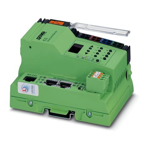
sysmik Scalibur SCA-340 User manual

Rev.22
Scalibur – Modular Controllers
SCA-340 / SCA-340-L
Manual

Disclaimer / Impressum
2 sysmik.de Manual SCA-340 / SCA-340-L
This manual is intended to provide support for installation and usage of the device. The
information is believed to be accurate and reliable. However, SysMik GmbH Dresden
assumes no responsibility for possible mistakes and deviations in the technical
specifications. SysMik GmbH Dresden reserves the right to make modifications in the
interest of technical progress to improve our modules and software or to correct mistakes.
We are grateful to you for criticism and suggestions. Further information (device description,
available software) can be found on our homepage www.sysmik.de. Please ask for latest
information.
SysMik disclaims all warranties in case of improper use or disassembly and software
modifications not described in this document or when using improper or faulty tools.
Commissioning and operation of the device by qualified personnel only. All applicable
regulations have to be observed.
SysMik®and the SysMik logo are registered trademarks of SysMik GmbH Dresden.
All other trademarks mentioned in this document are registered properties of their owners.
These and further trademarks are used in this document but not marked for better
readability.
No part of this document may be reproduced or modified in any form without prior written
agreement with SysMik GmbH Dresden.
Copyright © 2018 by SysMik GmbH Dresden
SysMik GmbH Dresden Tel + 49 (0) 351 – 4 33 58 – _0
Bertolt-Brecht-Allee 24 Fax + 49 (0) 351 – 4 33 58 – 29
Germany Homepage https://www.sysmik.de

Contents
Manual SCA-340 / SCA-340-L sysmik.de 3
Contents
1. Introduction 6
2. Device and System Overview 7
2.1 Hardware 7
2.1.1 Functional Overview 7
2.1.2 Processor Core 7
2.1.3 Ethernet 7
2.1.4 Serial Ports 8
2.1.5 USB 8
2.1.6 LON 8
2.1.7 Inline Local Bus Interface / Modular IO Terminals 8
2.2 Software Overview 9
2.2.1 Scalibur System Shell 9
2.2.2 IO Server 9
2.2.3 Commissioning Web Server 9
2.2.4 Sedona Virtual Machine 9
2.2.5 Niagara Framework 10
3. Installation and Commissioning 11
3.1 Assembly 11
3.1.1 Dimensions 11
3.1.2 Mounting 12
3.1.3 Adding Inline Terminals 13
3.2 Connections 14
3.2.1 Connectors 14
3.2.2 Power Supply 15
3.2.2.1 How to Connect Power 15
3.2.2.2 Power Dissipation Calculations for a Scalibur Controller 17
3.2.2.3 Current Consumption Calculation for a Scalibur Station (with Terminals) 18
3.2.2.4 Derating of Terminal and USB Supply 18
3.2.2.5 Protective Devices of 24 V Main and Segment Supply UMand US20
3.2.3 RS-485 and LON 20
3.2.4 Ethernet 21
3.2.5 USB-OTG for local Access 22

Contents
4 sysmik.de Manual SCA-340 / SCA-340-L
3.2.6 USB 23
3.3 Operating Elements 24
3.3.1 Overview 24
3.3.2 Inline Supply LEDs “US”, “UM”, “UL” 24
3.3.3 Process Status LEDs “PL”, “ST”, “SE” 24
3.3.4 IO Status LED “IO” 25
3.3.5 Communication LEDs “COM1”, “COM2”, “LON” 25
3.3.6 Service Button and LED “SV” 26
3.3.7 Ethernet Status LEDs 26
3.3.8 RS-485 Termination 27
4. Software 28
4.1 Configuration Tools 28
4.1.1 SCA System Shell 29
4.1.2 Commissioning Website 29
4.1.3 File Access via FTP 30
4.2 Commissioning Scalibur 30
4.2.1 IP Addressing 31
4.2.2 Time and Time Zone 31
4.2.3 Hardware Data Point Test 31
4.3 Ethernet Switch for Flexible Network Topologies 33
4.3.1 Assignment of IP Interfaces to External Ethernet Ports 33
4.3.2 Ethernet Ring Monitoring 35
4.3.3 Rapid-Spanning-Tree-Protocol (RSTP) 35
4.3.4 Port Status Informations 36
4.3.5 Broadcast Storm Protection 36
4.4 Real-Time Control with Scalibur and Sedona 37
4.4.1 IO Access 37
4.4.2 Modbus 37
4.4.3 Platform Service 38
4.5 Integration with Scalibur and Niagara Framework 39
4.5.1 Local IO Access 39
4.5.2 Serial Interfaces 41
4.5.3 IO Remote Control 43
4.5.4 Sedona Integration 43

Contents
Manual SCA-340 / SCA-340-L sysmik.de 5
4.6 Concurrent Access to the IO Terminals 44
5. Best Practices and Troubleshooting 46
5.1 Performance and Resource Management 46
5.2 Reliability of Nonvolatile Memory 47
5.3 Diagnosis and Troubleshooting 47
5.3.1 SCA System Shell / Commissioning Website is not accessible 48
5.3.2 IP Address unknown 48
5.3.3 No IP Communication 48
5.3.4 Unknown Niagara Platform Access Credentials 48
5.3.5 No Platform Connection to Device - Platform Daemon is not starting 49
5.3.6 Sedona Virtual Machine is not Starting 49
5.3.7 IO Errors 49
6. Technical Data 50
7. Order Information 53
7.1 Scalibur and Accessories 53
7.2 Supported Inline Automation Terminals 54
8. Glossary 56
9. Third-Party Software 57
10. Bibliography 58

Introduction
6 sysmik.de Manual SCA-340 / SCA-340-L
1. Introduction
Scalibur is a powerful modular controller for Niagara and Sedona. Scalibur stands
for scalability, a major characteristic of this controller. Scalability comprises several
aspects:
1) Scalable IO
A Scalibur station consists of the Scalibur controller and up to 63 terminals of the
modular Inline system. The terminals are available in a wide variety of types:
digital and analog inputs and outputs with different numbers of channels as well
as functional terminals for DALI light control, pulse metering, MBUS or serial
interfaces.
2) Scalable software
Scalibur has been developed primarily for the Niagara framework. Niagara
applications are built with the software tool Niagara Workbench. While Niagara
is very powerful, it is not very well suited for specific real-time applications. In
order to realize such applications with Scalibur too, the controller has the
Sedona framework in parallel to Niagara. Sedona applications run with fixed
cycle times in the millisecond range and are created with the
Niagara Workbench. Beside the separate exclusive use of either framework, the
parallel use of Niagara and Sedona is supported. The Niagara and Sedona
application can communicate to each other with a Sedona driver for Niagara.
3) Scalable licensing
The license model for Scalibur is very flexible: a license comprises a certain
number of data points which can be integrated with Scalibur. These license
packs are available as first-time license (250/500/1250/5000/10000 data points)
or as upgrade license (500/1250/2500 data points). Sedona, as open source
project, doesn’t have any license fees.
4) Scalable IP network
Scalibur contains two logically separated IP interfaces and an integrated
Ethernet switch with four external ports. The configurable assignment of the
Ethernet ports to the separate IP interfaces and the usage of the spanning-tree-
protocol allow flexible topologies like daisy-chain and redundant ring-structures
for both the backbone and the local control network.

Device and System Overview
Manual SCA-340 / SCA-340-L sysmik.de 7
2. Device and System Overview
2.1 Hardware
2.1.1 Functional Overview
Fig. 2.1.1.1: SCA-340-L basic circuit diagram
2.1.2 Processor Core
Processor: ARM®Cortex®A8 / 1 GHz
DDR3 SDRAM: 1 GB RAM (512 MiB for hardware version < 06 – see serial label)
eMMC Flash: 1,8 GB
NVRAM: 512 KiB / (buffered for a power failure of 5 days)
RTC: buffered for a power failure of 5 days
The internal Flash memory can be extended with a microSD card.
2.1.3 Ethernet
The integrated Ethernet switch has 4 external ports, which can be assigned
independently to one of the two separate IP interfaces. If at least two ports belong to
an IP interface, then redundant communication paths can be established, for
example by connecting several devices in a ring. The Ethernet switch supports the
Rapid Spanning Tree Protocol (RSTP), as well as a ring monitoring function to
automatically switch off redundant paths, and a broadcast storm protection function.
Factory default: eth0 is assigned to LAN3/LAN4, eth1 is assigned to LAN1/LAN2,
and RSTP and ring monitoring are deactivated.

Device and System Overview
8 sysmik.de Manual SCA-340 / SCA-340-L
2.1.4 Serial Ports
Both RS-485 ports have switches for bias and terminating resistors, and are
galvanically isolated from each other and the rest of the circuit.
Further serial interfaces may be added using modular IO terminals (M-Bus, RS-232,
RS-485, RS-422).
2.1.5 USB
USB 1 is a USB-OTG port with Mini-USB socket, and is used for installation and
maintenance. Connected to a PC, it allows to control the device via console and to
access the internal installation web site for device configuration and data point test.
The second USB port (USB 2) allows to connect USB end-devices.
2.1.6 LON
The SCA-340-L has a LON interface according to the CEA-709 standard, to connect
directly to LonMark TP/FT-10 networks.
2.1.7 Inline Local Bus Interface / Modular IO Terminals
The local bus interface allows to connect up to 63 modular IO terminals. This
interface comprises the communication channel to the IO terminals as well as the
power supply of these terminals and their connected sensors and actuators.
Scalibur is a controller for the Inline IO system and unlocks the rich pool of Inline IO
terminals for building automation.
Inline is a modular IO system by Phoenix Contact, to flexibly and quickly build up
space-saving automation stations. An Inline station consists of a bus controller and
a set of IO terminals, chosen freely in terms of numbers, type, and sequential
arrangement. The bus controller runs the Inline station and has interfaces to the
higher level controller. Up to 63 IO terminals can be connected to a bus controller.
There are IO terminals for almost any purpose:
digital inputs and outputs with 1, 2, 4, 8, 16, or 32 channels per terminal
Triac and relay outputs for switching signals or for higher loads
analog inputs for measuring voltage, current, resistance, or temperature
with 2, 4, or 8 channels per terminal
analog outputs for voltage or current with 2, 4, or 8 channels per terminal
function terminals for complex IO operations or gateway functions (DALI,
M-Bus, S0 pulse metering, serial interface)
supply and support terminals , e.g. to realize separated voltage domains
within an Inline station
The overall width of the Inline extension terminals is 1, 2 or 4 DU (1 DU, division
unit = 12.2 mm or approx. 0.48 in.).
Inline terminals are provided with a pluggable wiring level enabling pre-wiring and
easy module exchange.
The mechanics of the system also allows exchanging terminals without complete
dismantling of the station.
Scalibur determines type and function of all supported terminals automatically, thus
certain in- and output functions can also be created without a previous configuration
of the station, which is especially helpful for commissioning tests.

Device and System Overview
Manual SCA-340 / SCA-340-L sysmik.de 9
2.2 Software Overview
Scalibur is using a Linux operating system, which runs several applications in
parallel.
Fig. 2.1.7.1: Scalibur software structure
2.2.1 Scalibur System Shell
The Scalibur System Shell is accessible only via the local USB-OTG port, and is
used during commissioning to configure basic settings like IP address, or as
maintenance access if IP address or passwords have been lost.
2.2.2 IO Server
The IO server controls the modular Inline terminals of the Scalibur station and
manages concurrent accesses to the hardware data points. Niagara and the IO
server communicate via an TCP connection. This allows to control IOs remotely
from another Niagara station. The remote access can be limited or disabled by the
setting of the IP address of the controlling station.
2.2.3 Commissioning Web Server
The commissioning web server is exclusively accessible via the local USB-OTG
port. It presents web pages to commission the device: setting IP addresses and time
zone, reading state of inputs and setting output states of the data points of the local
IO terminals for test purposes.
2.2.4 Sedona Virtual Machine
The Sedona virtual machine (SVM) runs the Sedona application in real-time with
configurable cycle time. The Niagara Workbench connects to the SVM to modify the
application, load updates, or create backups of the application. Platform specific kits
provide access to the IO terminals, and also to system settings like IP addresses

Device and System Overview
10 sysmik.de Manual SCA-340 / SCA-340-L
and Modbus settings. A Modbus TCP server and a Modbus TCP client/Modbus RTU
master are integrated and are used to exchange data with other Sedona controllers.
Also, Niagara can be deactivated here.
2.2.5 Niagara Framework
Scalibur can be parameterized with Niagara Workbench and a platform connection
to the Niagara daemon. This includes loading of software updates and of a station
(Niagara application), which can be run automatically by the Niagara daemon.
A Workbench connection to a station is used to modify the station. All features of the
Niagara framework are available:
data point integration over a plethora of open automation protocols (LON,
BACnet, KNX, M-Bus, Modbus, and others) with data normalization
system functions (scheduler, alarming, trend log)
web visualization
enterprise interfaces (oBIX, data bases) and many more

Installation and Commissioning
Manual SCA-340 / SCA-340-L sysmik.de 11
3. Installation and Commissioning
3.1 Assembly
3.1.1 Dimensions
Width x Height x Depth:
80 mm x 119,8 mm x 71,5 mm (3.15 inch x 4.72 inch x 2.81 inch)
Fig. 3.1.1.1: Scalibur dimensions

Installation and Commissioning
12 sysmik.de Manual SCA-340 / SCA-340-L
3.1.2 Mounting
Preferred mounting position is horizontal (i.e. on a horizontal DIN rail which is
attached to a vertical wall). For all other mounting positions, a derating has to be
observed (see chapter 6).
Note: The air vents have to be kept free with a sufficient spacing to other components, to
ensure optimal air ventilation.
The device is designed for easy snap in mounting on 35 mm x 7.5 mm
DIN EN 60715 rails (formerly DIN EN 50022).
Note: The DIN rail should be attached to a mounting plate or an even back plane for best
stability.
Suitable fixtures, like end clamps or grounding terminals have to be used at both
ends of the station, to prevent sliding off the rail.
Note: To ensure easy unlocking of the Ethernet connectors, use only clamps at the bus
controller side of the station that do not protrude more than 30 mm from the rail.
Note: Only use clean and corrosion free mounting rails in order to ensure a safe contact
between the FE terminals.

Installation and Commissioning
Manual SCA-340 / SCA-340-L sysmik.de 13
3.1.3 Adding Inline Terminals
An Inline station is assembled by plugging the individual components to each other,
thus establishing the potential and bus signal connection between the individual
components of the station. Figure 3.1.3.1 shows the procedure of mounting a
terminal.
Disconnect power to the entire station.
Mount the electronics base onto the rail (A). Adjacent terminals are
interlocked by their feather keys / keyways (B).
First insert the feather keys of the local bus into the keyways of the
preceding terminal (B1).
Guide the feather keys along the keyways until they lock appropriately
(B2).
Ensure that the feather keys are properly connected (C2). C1 shows the
common mistake that the feather keys are not inside their keyways.
After mounting all electronics bases install the connectors onto their
respective bases. First insert the front detent (D1). Then push the
connector onto the electronics base until the rear detent locks properly
(D2).
Figure 3.1.3.1: Installation on the mounting rail (A), connection of Inline components to each other (B),
connection check (C), plugging of the wiring level (D)
Note: While connecting the components to each other and to the mounting rail later, please
make sure that all feather keys and latches are properly snapped in!
Note: Please consult the User Manual with regard to configuration and installation of the
Inline product family (see [1]).
6452B010

Installation and Commissioning
14 sysmik.de Manual SCA-340 / SCA-340-L
3.2 Connections
3.2.1 Connectors
1
Micro-SD card slot
8
Switches for RS-485 termination / bias
2
Type label with device-specific
information
9
Service interface
3
Service button
10
Bus interface connector
4
Ethernet (4x 10/100BaseT)
11
Supply connector
5
FE connector *)
12
Labeling field (2x)
6
USB 1 (mini USB, USB-OTG)
13
Diagnostic indicators
7
USB 2
14
End plate
*) … The FE connector is placed at the rear side of the connector – it is not visible in the
sketch.
Fig. 3.2.1.1: Overview device connections

Installation and Commissioning
Manual SCA-340 / SCA-340-L sysmik.de 15
3.2.2 Power Supply
3.2.2.1 How to Connect Power
The bus controller is operated with 24 V DC. The bus controller is powered from this
source and it generates the logic voltage for the logic circuit and the analog voltage
for the analog circuit. The logic circuit supplies the internal bus including the
communication chips of all connected automation I/O terminals. The analog circuit
provides an auxiliary supply for analog signals.
Note: While connecting the automation terminals please observe the derating of the logic
voltage, the supply of the analog terminals, and the maximum ampacity of the terminals.
Furthermore the bus controller includes connections for the supply of the mains and
segment voltage of the Inline station.
Fig 3.2.2.1 shows the basic circuit for the connections of the power supply.
Fig. 3.2.2.1: Supply of UM/ UBK and USfrom different sources (A) and from a common source (B)
Note: If UBK/UMand USare to be supplied from a common source, the fuse protection of the
individual sections with regard to their supply requirements has to be observed.
Note: The current passing through terminals and potential routing contacts must not exceed
8 A.

Installation and Commissioning
16 sysmik.de Manual SCA-340 / SCA-340-L
The Functional Earth ground FE is connected to the potential routing contacts and is
automatically grounded if the bus controller is snapped on a grounded mounting rail.
The function of FE is to discharge interferences.
Note: Functional earth ground (1.4 and. 2.4) has to be connected additionally via 1.5 mm²
wire (AWG 15) and grounding terminal to the mounting rail (see Fig. 3.2.2.2).
Fig. 3.2.2.2: Connecting functional earth ground (FE) of Scalibur

Installation and Commissioning
Manual SCA-340 / SCA-340-L sysmik.de 17
Terminal
point
Name Function
1.1 US
24 V DC segment supply (segment circuit); The supplied voltage
is lead to the automation terminals via the potential routing
contacts.
2.1
1.2, 2.2 UBK / UM
U
BK
: 24 V DC bus controller supply, logic supply (U
L
) and analog
supply (UANA)
UM: 24 V DC main voltage (main circuit); The supplied voltage is
lead to the automation terminals via the potential routing
contacts
1.3, 2.3 GND
Reference ground for the internal bus and automation terminals
(logic and analog circuit) and for the main and segment supply
(main and segment circuit).
1.4, 2.4 FE
Functional ground; Connecting the functional ground to this
terminal point is mandatory (see above). The terminal point is
internally connected to the potential routing contacts and the FE
contact at the back side of the enclosure.
Table 3.2.2.1.1: Terminal assignment of supply connector
3.2.2.2 Power Dissipation Calculations for a Scalibur Controller
The power dissipation of the bus controller equals the sum of the power
requirements of the bus controller itself and the power loss of the internal power
supply for the whole Inline station:
PSCA=
PO+
PUSB+
PPERI
PSCA power dissipation of the bus controller
POpower requirements for operating the bus controller without
terminals and any external load (4.1 W)
PUSB power dissipation of the bus controller caused by the load on
USB1 and USB2 (max. 500 mA each)
PUSB = 0.7 V × ( IUSB1 + IUSB2)
PPERI power dissipation of the bus controller caused by the Inline IO
terminals
PPERI= 1.0 V × IL
ILcurrent consumption of UL
Note:The factors 1.1 V und 0.7 V result from the electrical efficiency of the internal power
supply unit.
Sample calculation: Power dissipation of a Scalibur in case of the maximum
possible current drawn from ULand a USB memory stick with 0.1 A current
consumption.
PSCA = 4.1 W + 0.7 V × 0.1 A + 1.0 V × 2.0 A
PSCA = 4.1 W + 0.07 W + 2.0 W
PSCA = 6.17 W

Installation and Commissioning
18 sysmik.de Manual SCA-340 / SCA-340-L
3.2.2.3 Current Consumption Calculation for a Scalibur Station (with Terminals)
To find a suitable external power supply, the current consumption of the entire
Scalibur station has to be considered:
IIS= ISCA + IUSB + IK+ IAS
IIS current consumption of the entire Scalibur Inline station
ISCA current consumption of the Scalibur
IUSB current consumption of connected USB devices
IKcurrent consumption of connected terminals
IAS current consumption of sensors and actuators, fed by the Inline station
The current consumption of a Scalibur (without terminals) is maximum 170 mA.
ISCA = 0.17 A
Please consult the manual of the connected USB device to find out the actual
current draw from USB.
The respective USB currents IUSB1 and IUSB2 are weighted by a factor of 0.24,
resulting in the equation:
IUSB = (IUSB1 + IUSB2) × 0.24
The current consumption of the connected terminals can be found in their manuals.
The following rules of thumb apply:
The current provided by UANA influences the total current directly.
The current provided by ULapplies to the total current with a factor of 0.36.
The following formula applies:
IK= IA+ IL× 0.36
IAcurrent from UANA (max. 500 mA)
ILcurrent from UL(max. 2.0 A)
See the according datasheets in order to determine the current consumption of the
connected actuators and sensors.
For an estimation it is often sufficient to check, whether the supply can be provided
completely by the Scalibur, that is without power or boost terminals.
Without power and boost terminals and regardless of the circuits UMund US, the
maximum current consumption of the Scalibur with connected terminals is 1.7 A.
In addition there are the current requirements of the sensors and actuators, whereas
the current through feather keys and keyways is limited to a maximum of 8 A.
Note: When selecting an external power supply, plan sufficient reserves. also into account
that it could come to a current increase to a multiple of the rated current in the moment of
turn-on caused by input capacities. Power supplies with over current shut-down must have a
sufficient response delay to avoid start-up problems.
3.2.2.4 Derating of Terminal and USB Supply
Because USB and the Inline terminals are supplied by Scalibur’s internal power
supply unit, an increased load there increases Scalibur’s internal power dissipation.,
Therefore, a derating has to be observed, which is depending on the mounting
position (see Fig. 3.2.2.4). The recommended mounting position (with least derating)
is horizontally (that is, clipped to a horizontal DIN rail on the wall).
The internal power dissipation caused by USB loads (PUSB) and the connected Inline
terminals (PPERI) is calculated according to chapter 0.

Installation and Commissioning
Manual SCA-340 / SCA-340-L sysmik.de 19
Fig. 3.2.2.3: Derating diagram of maximum internal power dissipation
Please refer to the manuals of the Inline terminals to find out the load of the logic
supply.
Maximum load on the logic supply (2 A) and on USB (2 x 500 mA) leads to a 100%
power dissipation of 2.7 W:
PV= 1.0 V × IL+ 0.7 V × IUSB
PV= 1.0 V × 2.0 A + 0.7 V × 1.0
A = 2.7 W
This power dissipation can be maintained up to a maximum environmental
temperature of 40 °C (104 °F). For higher temperatures, the load (PPERI and PUSB)
must be reduced according to Fig. 3.2.2.3.
Example 1: Horizontal mounting position
For an environmental temperature of 55 °C (131 °F) and horizontal mounting, the
power dissipation is limited to 87 %, which means 2.35 W. Supposed ILis fully
loaded with the max. allowed 2 A, then the USB ports can support a maximum of
0,5 A:
IUSB = 0.87 PV– 1 V
×
IL
0.7 V
IUSB = 2.35 W – 2 W
0.7 V = 0.5 A
0
20
40
60
80
100
-25 -15 -5 515 25 35 45 55
Pv[%]
Tenv [°C]
horizontal mounting
other mounting positions
Tenv [°C] environmental temperature in °C
Pv[%] Power dissipation of internal Scalibur supply in %

Installation and Commissioning
20 sysmik.de Manual SCA-340 / SCA-340-L
Example 2: Other mounting positions
For an environmental temperature of 45 °C (113 °F) and non-horizontal mounting,
using additionally a USB device with 200 mA, the power dissipation is limited to
70 %, i.e. 1.89 W. Therfore, the max. current from ULis:
IL= 0.7 PV– 0.7 V
×
IUSB
1 V
IL= 1.89 W – 0.14
W
1 V = 1.75
A
3.2.2.5 Protective Devices of 24 V Main and Segment Supply UMand US
Surge / overvoltage: Input protective diodes (can be destroyed by permanent
overload).
Polarity reversal: Parallel diodes. In case of wrong polarity a high current is flowing
which is blowing the external fuses.
Segment supply and main supply are related to the same ground potential.
Note: Each 24 V voltage supply must be fused externally. The power supply unit must be
capable of supplying a current four times the nominal value of the external fuse to reliably
blow the fuses in case of an error.
3.2.3 RS-485 and LON
The interface connector provides terminals for both RS-485 interfaces and (for
SCA-340-L only) the LON TP/FT-10 interface.
Fig. 3.2.3.1: RS-485/LON Interface terminal connections
This manual suits for next models
1
Table of contents
Other sysmik Controllers manuals
Popular Controllers manuals by other brands

BRV
BRV ModvlvS Logico Installation and operating instructions

Siemens
Siemens N 523/11 Technical product information

Siemens
Siemens SIMATIC FM 452 manual

Carrier
Carrier i-Vu MPC Open XP IO48/816 Installation and startup guide

SMSC
SMSC USB2513i Specification sheet

Bosch
Bosch AMC2 Series installation manual