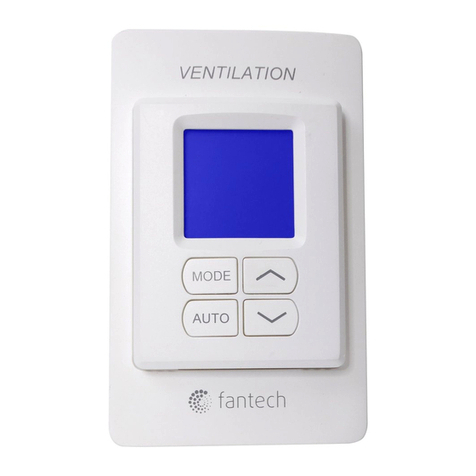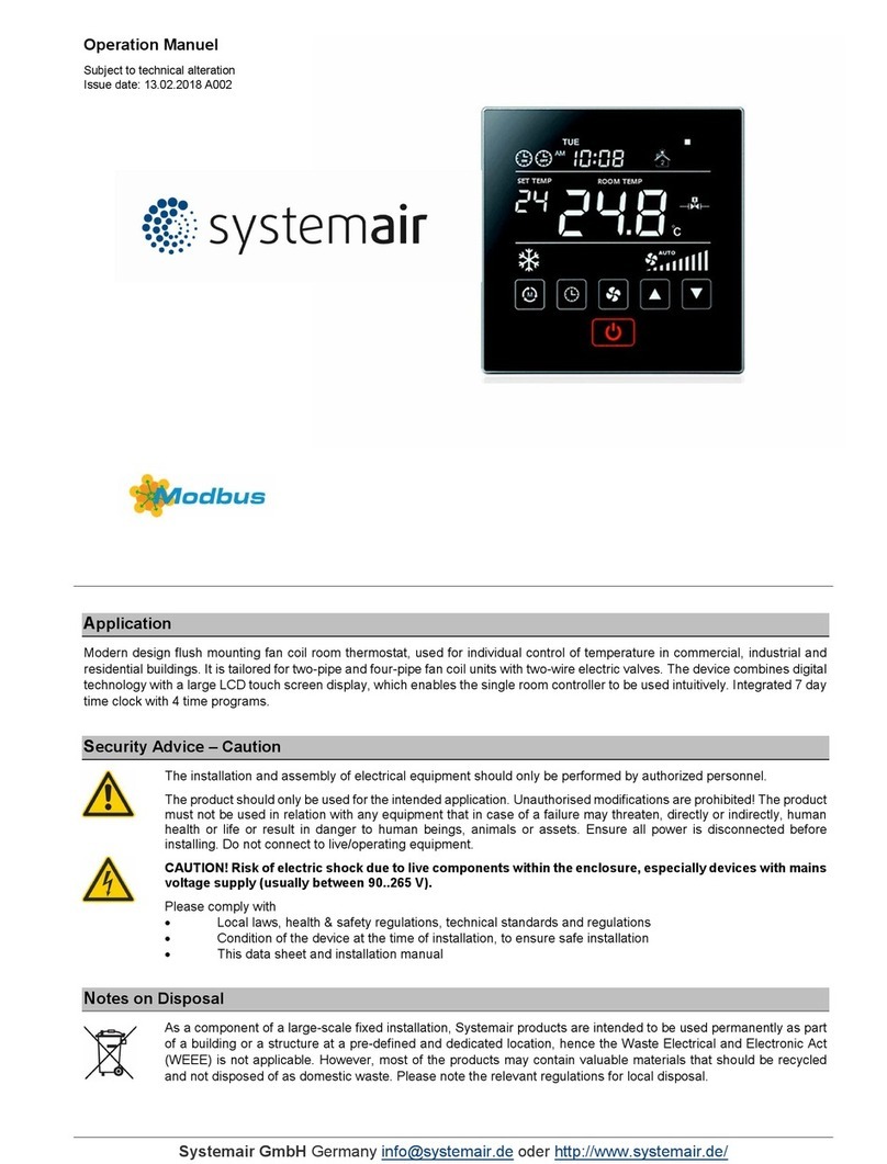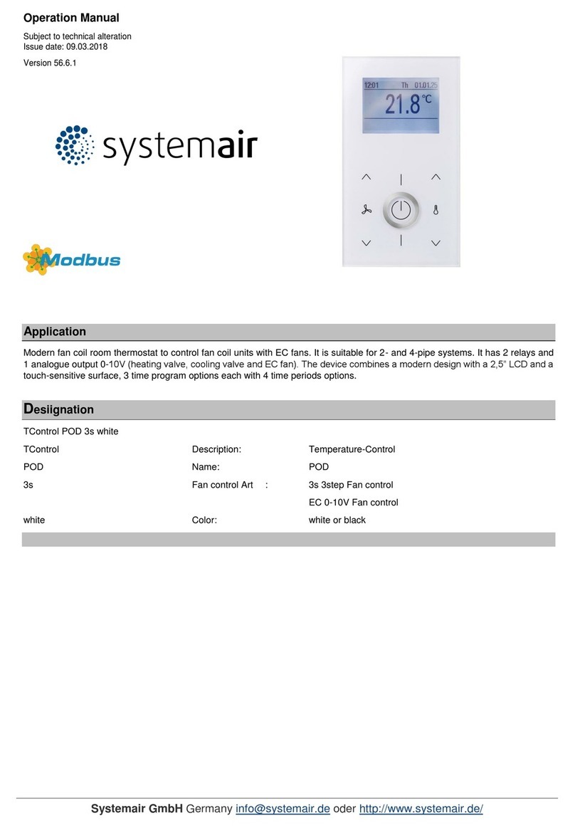
TControl Easy DX-Air Curtain (Item No. 189421)
Room thermostat for DX air curtain
SYSTEMAIR GmbH Germany info@systemair.de oder http://www.systemair.de
Issue date: 03.11.2020 Page 2 / 11
»REMARKS TO ROOM SENSORS
Location and Accuracy of Room Sensors
The room sensor should be mounted in a suitable location for measuring accurate room temperature. The accuracy of the temperature
measurement also depends directly on the temperature dynamics of the wall. It is important, that the back plate is completely flush to the wall so
that there is sufficient circulation of air through the vents in the cover, otherwise, deviations in temperature measurement will occur due to
uncontrolled air circulation. The temperature sensor should not be covered by furniture or other objects. Mounting next to doors (due to draught)
or windows (due to colder outside wall) should be avoided.
Surface and Flush Mounting
The measuring result is influenced by the thermal characteristics of the wall. A solid concrete wall responds to thermal fluctuations within a room
in a much slower than a light-weight structure wall. Room temperature sensors installed in flush-mounted boxes have a longer response time to
thermal variations. In extreme cases they detect the radiant heat of the wall even if the air temperature in the room is lower for example. The
quicker the dynamics of the wall (temperature acceptance of the wall) or the longer the selected inquiry interval of the temperature sensor is the
smaller the deviations limited in time are.
»TECHNICAL DATA
2x 0..10 V for heating and cooling, min. load 10 kΩ
terminal 1 | 3 - terminal 1 | 4
2x 0..10 V for fan, min. load 10 kΩ
250 V, max. load. 3 A
250 V, max. load. 3 A
RS485 Modbus, RTU, half-duplex, baud rate 4.800, 9.600, 19.200 or 38.400, parity: non (2 stopbits), even
or odd (1 stopbit)
24 V = (±10%) | 24 V ~ (±20%) SELV
input for external sensor
NTC10K
terminal 9 | 11 – Occupancy
input digital for floating contact
terminal 9 | 12 - Defrost
input digital for floating contact
set point adjustment +1..+50 °C, (default +16..+30 °C)
LCD 64x41 mm, white background lighting
IP20 according to EN 60529
terminal block max. 1,5 mm²
-10..+50 °C, max. 95% rH non-condensing
flush mounted with standard EU box (Ø=60 mm)
*Power supply
When several BUS devices are supplied by one 24 V AC voltage supply, it is to be ensured that all “positive” operating voltage input terminals (+)
of the field devices are connected with each other and all “negative” operating voltage input terminals (-) (=reference potential) are connected
together (in-phase connection of field devices).
In case of reversed polarity at one field device, a supply voltage short-circuit would be caused by that device. The consequential short-circuit
current flowing through this field my cause damage to it.
Therefore, pay attention to correct wiring.
