manuals.online logo
Brands
  1. Home
  2. •
  3. Brands
  4. •
  5. System Sensor
  6. •
  7. Speakers
  8. •
  9. System Sensor SPSWL-ALERT User manual

System Sensor SPSWL-ALERT User manual

1 I56-0003-001
01-12
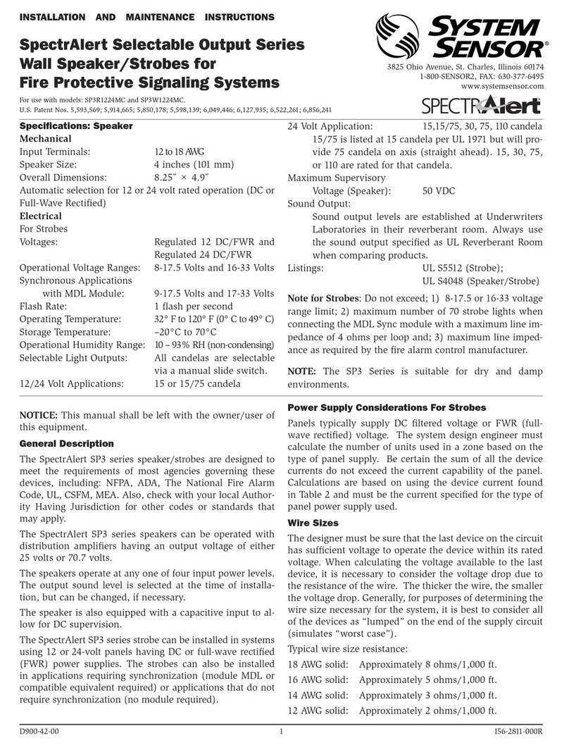
For use with the following models:
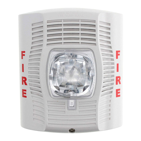
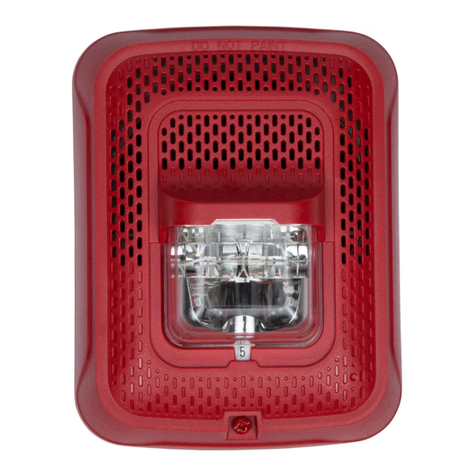
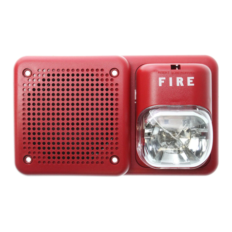
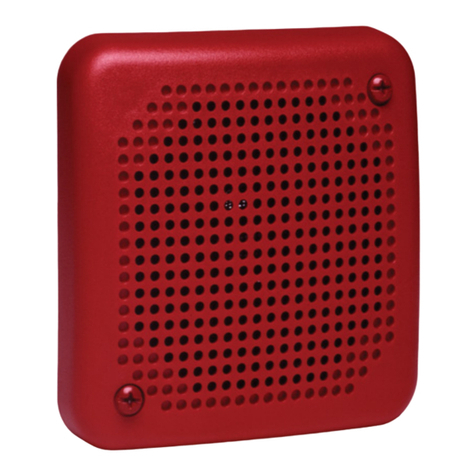
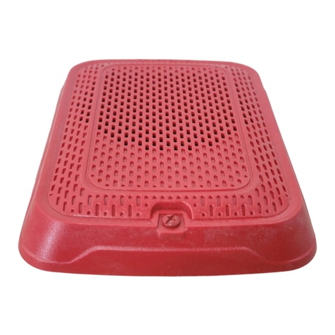
Wall Speakers: SPSWL-ALERT
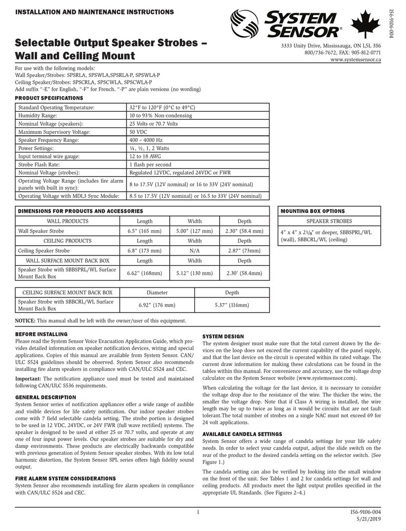
PRODUCT SPECIFICATIONS
Standard Operating Temperature: 32°F to 120°F (0°C to 49°C)
Humidity Range: 10 to 93% Non-condensing
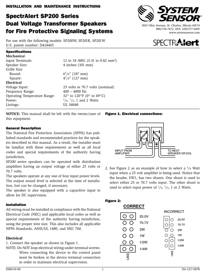
Nominal Voltage (speakers): 25 Volts or 70.7 Volts
Maximum Supervisory Voltage: 50 VDC
Speaker Frequency Range: 400 – 4000 Hz
Power Settings: ¼, ½, 1, 2 Watts
Input terminal wire gauge: 12 to 18 AWG
Strobe Flash Rate: 1 flash per second
Nominal Voltage (strobes): Regulated 12VDC, regulated 24VDC or FWR
Operating Voltage Range (includes fire alarm
panels with built in sync): 8 to 17.5V (12V nominal) or 16 to 33V (24V nominal)
Operating Voltage with MDL3 Sync Module: 8.5 to 17.5V (12V nominal) or 16.5 to 33V (24V nominal)
DIMENSIONS FOR PRODUCTS AND ACCESSORIES MOUNTING BOX OPTIONS
WALL PRODUCTS Length Width Depth SPEAKER STROBES
Wall Speaker Strobe 6.5" (165 mm) 5.00" (127 mm) 2.30" (58.4 mm) 4" x 4" x 2
1
/
8
" or deeper,
SBBSPRL/WL (wall)
WALL SURFACE MOUNT BACK BOX Length Width Depth
Speaker Strobe with SBBSPRL/WL Surface
Mount Back Box 6.62" (168mm) 5.12" (130 mm) 2.30" (58.4mm)
NOTICE: This manual shall be left with the owner/user of this equipment.
BEFORE INSTALLING
Please read the System Sensor Voice Evacuation Application Guide, which
provides detailed information on speaker notification devices, wiring and
special applications. Copies of this manual are available from System Sensor.
NFPA 72 and NEMA guidelines should be observed. System Sensor also rec-
ommends installing fire alarm speakers in compliance with NFPA 72, ANSI/
UL 1480 and NEC 760
Important: The notification appliance used must be tested and maintained
following NFPA 72 requirements.
GENERAL DESCRIPTION
System Sensor series of notification appliances offer a wide range of audible
and visible devices for life safety notification. Our indoor speaker strobes
come with 7 field selectable candela setting. The strobe portion is designed
to be used in 12 VDC, 24VDC, or 24V FWR (full wave rectified) systems. The
speaker is designed to be used at either 25 or 70.7 volts, and operate at any
one of four input power levels. Our speaker strobes are suitable for dry and
damp environments. These products are electrically backwards compatible
with previous generation of System Sensor speaker strobes. With its low total
harmonic distortion, the System Sensor SPL series offers high fidelity sound
output.
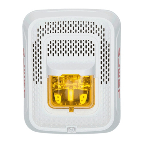
System Sensor amber lens ALERT Speakers Strobes are private mode notifica-
tion appliances intended to alert trained personnel to investigate a life safety
event. The speaker is listed to ANSI/UL 1480 (public mode) and the strobe is
listed to ANSI UL 1638 (private mode).
FIRE ALARM SYSTEM CONSIDERATIONS
System Sensor also recommends installing fire alarm speakers in compliance
with NFPA 72, ANSI/UL 1480 and NEC 760.
SYSTEM DESIGN
The system designer must make sure that the total current drawn by the de-
vices on the loop does not exceed the current capability of the panel supply,
and that the last device on the circuit is operated within its rated voltage. The
current draw information for making these calculations can be found in the
tables within this manual. For convenience and accuracy, use the voltage drop
calculator on the System Sensor website (www.systemsensor.com).
When calculating the voltage for the last device, it is necessary to consider
the voltage drop due to the resistance of the wire. The thicker the wire, the
smaller the voltage drop. Note that if Class A wiring is installed, the wire
length may be up to twice as long as it would be circuits that are not fault
tolerant. The total number of strobes on a single NAC must not exceed 69 for
24 volt applications.
AVAILABLE CANDELA SETTINGS
System Sensor offers a wide range of candela settings for your life safety
needs. In order to select your candela output, adjust the slide switch on the
rear of the product to the desired candela setting on the selector switch. (See
Figure 1.)
The candela setting can also be verified by looking into the small window on
the front of the unit. See Table 1 for candela settings for wall products. All
products meet the light output profiles specified in the appropriate UL Stan-
dards. (See Figures 2 and 3.)
For amber lensed strobes used for full profile measurement, listed candela rat-
ings must be reduced in accordance with Table 2.
FIGURE 1. CANDELA SELECTOR
A0486-00
CURRENT DRAW RATINGS
For the strobe, the current draw for each setting is listed in Table 1.
INSTALLATION AND MAINTENANCE INSTRUCTIONS
3825 Ohio Avenue, St. Charles, Illinois 60174
800/736-7672, FAX: 630/377-6495
www.systemsensor.com
I56-0003-001
Selectable Output Amber Lens ALERT
Speaker Strobe – Wall Mount
2 I56-0003-001
01-12
WIRING AND MOUNTING
All wiring must be installed in compliance with the National Electric Code
and the local codes as well as the authority having jurisdiction. Wiring must
not be of such length or wire size which would cause the notification appli-
ance to operate outside of its published specifications. Improper connections
can prevent the system from alerting occupants in the event of an emergency.
Wire sizes up to 12 AWG (2.5 mm²) may be used with the mounting plate. The
mounting plate ships with the terminals set for 12 AWG wiring.
Make wire connections by stripping about
3
/
8
" of insulation from the end of
the wire. Then slide the bare end of the wire under the appropriate clamping
plate and tighten the clamping plate screw.
See Figure 4 for wiring terminals and strip guide reference.
1. Connect the speaker as shown in Figure 4.
2. There are two rotary switches on the back of the product. The first switch
is used to select either 25 or 70.7 volts input and the second switch is used to
select the input power of ¼, ½, 1 or 2 watts. (See Figure 5.)
FIGURE 4. WIRING DIAGRAM AND WIRING TERMINALS
(-)
(+)
(-)
(+)
(-)
(+)
(-)
(+)
From FACP
OUTPUT
To Next Device or EOL
From Amplifier
INPUT
To Next Device or EOL
A0519-00
Wiring Terminals
1. Negative (-). Line in and out
2. Positive (+). Line in and out
3. Positive (+). Line in and out
NOTE: Do not loop electrical wiring un-
der terminal screws. Wires connecting
the device to the control panel must be
broken at the device terminal connec-
tion in order to maintain electrical su-
pervision.
FIGURE 5. SPEAKER WATTAGE AND VOLTAGE SETTINGS
A0419-01
SHORTING SPRING FEATURE
System Sensor notification appliances come with a shorting spring that is pro-
vided between terminals 2 and 3 of the mounting plate to enable system con-
tinuity checks after the system has been wired, but prior to installation of the
final product. (See Figure 6.) This spring will automatically disengage when
the product is installed, to enable supervision of the final system.
TABLE 1. WALL-MOUNT STROBE CURRENT DRAW (mA)
Candela
8-17.5
Volts 16-33 Volts
DC DC FWR
15 88 43 60
NOTE: Products set at 15 and 30
candela automatically work on ei-
ther 12V or 24V power supplies.
The products are not listed for
12V DC operation when set to any
other candela settings.
30 143 63 83
75 - 107 136
95 - 121 155
110 - 148 179
135 - 172 209
185 - 222 257
TABLE 2. CANDELA DE-RATING BY LENS COLOR
Wall Candela
Setting
Private Mode Emergency Warning
15 15 12
30 30 24
75 75 60
95 95 75
110 110 85
135 135 105
185 185 145
FIGURE 2. WALL LIGHT OUTPUT – FIGURE 3. VERTICAL
HORIZONTAL DISPERSION DISPERSION, WALL TO FLOOR
Degrees* Percent of
Rating Degrees* Percent of
Rating
0100 0100
5-25 90 5-30 90
30-45 75 35 65
50 55 40 46
55 45 45 34
60 40 50 27
65 35 55 22
70 35 60 18
75 30 65 16
80 30 70 15
85 25 75 13
90 25 80 12
Compound 45
to the left 24 85 12
Compound 45
to the right 24 90 12
A0467-00
A0469-00
*Tolerance of ±1 degree is permitted.
Thisisgenerated textforfigtxt.
3 I56-0003-001
01-12
FIGURE 6. SHORTING SPRING
Shor
ting
Spring
WIRING TERMINALS
1. Negative (-). Line in and out
2. Positive (+). Line in and out
3. Positive (+). Line in and out
Strip Guide
A0499-01
AVAILABLE POWER SETTINGS
System Sensor offers a wide range of power settings for your life safety needs,
including ¼, ½, 1, and 2W.
Sound levels data per UL 1480 can be found in Table 3.
TABLE 3. SOUND LEVELS FOR EACH TRANSFORMER POWER SETTING
Setting UL Reverberant
(dBA @10 ft)
UL Anechoic
(dBA @10 ft)
¼ W 77 77
½ W 80 80
1 W 83 83
2 W 86 86
CAUTION
Signal levels exceeding 130% rated signal voltage can damage the speaker.
Consequently, an incorrect tap connection may cause speaker damage. This
means that if a 25V tap is selected when a 70.7V amplifier is being used,
speaker damage may result. Therefore, be sure to select the proper taps for the
amplifier voltage/input power level combination being used.
MOUNTING
1. Attach mounting plate to junction box. The mounting plate is compatible
with 4" x 4" x 2
1
/
8
" or deeper junction boxes. (See Figure 7.)
2. Connect field wiring to terminals, as shown in Figure 4.
3. If the product is not to be installed at this point, use the protective dust
cover to prevent contamination of the wiring terminals on the mounting plate.
4. To attach product to mounting plate, remove the protective dust cover, hook
tabs on the top of the product housing into the grooves on mounting plate.
5. Then, hinge the product into position to engage the pins on the product
with the terminals on the mounting plate. Make sure that the tabs on the back
of the product housing fully engage with the mounting plate.
6. Secure product by tightening the single mounting screw in the front of the
product housing.
CAUTION
The “hold in place” snaps are not intended to secure the product to the back
box. The product must be secured to the back box using the screws provided.
CAUTION
Factory finish should not be altered: Do not paint!
CAUTION
Do not over tighten mounting plate screws; this may cause mounting plate
to flex.
FIGURE 7. WALL SPEAKER
A0522-00
TAMPER SCREW
For tamper resistance, the standard
captive screw may be replaced with
the enclosed Torx screw.
1. To remove the captive screw, back
out the screw and apply pressure to
the back of the screw until it dis-
engages from the housing. Replace
with the supplied Torx screw. (See
Figure 8.)
FIGURE 8. TAMPER SCREW
A0502-00
NOTE: Wall speaker shown in this
example.
SURFACE MOUNT BACK BOX MOUNTING
1. The surface mount back box may be secured directly to the wall. A ground-
ing bracket with ground screw capability is provided if needed. For wall see
Figure 9.
FIGURE 9. WALL SURFACE MOUNT BACK BOX
A0523-00
2. The wall mount box must be mounted with the up arrow pointing up. (See
Figure 10.)
FIGURE 10. SMBB UP ARROW
A0481-00
3. Threaded knockout holes are provided for the sides of the box for ¾ inch
conduit adapter. Knockout holes in the back of the box can be used for ¾
inch rear entry.
4. To remove the ¾ inch knockout, we recommend you use a flat head screw-
driver, place the blade of the flat head screwdriver in the inner edge of the
knockout. Strike the screwdriver as you work your way around as shown in
Figure 11. NOTE: Use caution not to strike the knockout near the top edge
of the surface mount back box.
4 I56-0003-001
©2017 System Sensor. 01-12
System Sensor®is a registered trademark of Honeywell International, Inc.
Always make sure that the individual speakers are tested after installation per NFPA regulations.
The speakers may not be heard. The loudness of the speaker meets (or exceeds) cur-
rent Underwriters Laboratories’ standards. However, the speaker may not alert a sound
sleeper or one who has recently used drugs or has been drinking alcoholic beverages. The
speaker may not be heard if it is placed on a different floor from the person in hazard or
if placed too far away to be heard over the ambient noise such as traffic, air conditioners,
machinery or music appliances that may prevent alert persons from hearing the alarm.
The speaker may not be heard by persons who are hearing impaired.
WARNING
THE LIMITATIONS OF SPEAKERS
THREE-YEAR LIMITED WARRANTY
System Sensor warrants its enclosed product to be free from defects in materials and
workmanship under normal use and service for a period of three years from date of
manufacture. System Sensor makes no other express warranty for this product. No agent,
representative, dealer, or employee of the Company has the authority to increase or alter
the obligations or limitations of this Warranty. The Company’s obligation of this Warranty
shall be limited to the replacement of any part of the product which is found to be defec-
tive in materials or workmanship under normal use and service during the three year
period commencing with the date of manufacture. After phoning System Sensor’s toll
free number 800-SENSOR2 (736-7672) for a Return Authorization number, send defective
units postage prepaid to: Honeywell, 12220 Rojas Drive, Suite 700, El Paso TX 79936.
Please include a note describing the malfunction and suspected cause of failure. The
Company shall not be obligated to replace units which are found to be defective because
of damage, unreasonable use, modifications, or alterations occurring after the date of
manufacture. In no case shall the Company be liable for any consequential or incidental
damages for breach of this or any other Warranty expressed or implied whatsoever, even
if the loss or damage is caused by the Company’s negligence or fault. Some states do not
allow the exclusion or limitation of incidental or consequential damages, so the above
limitation or exclusion may not apply to you. This Warranty gives you specific legal
rights, and you may also have other rights which vary from state to state.
FCC STATEMENT
System Sensor speakers have been tested and found to comply with the limits for a Class
B digital device, pursuant to part 15 of the FCC Rules. These limits are designed to pro-
vide reasonable protection against harmful interference when the equipment is operated
in a commercial environment. This equipment generates, uses, and can radiate radio fre-
quency energy and, if not installed and used in accordance with the instruction manual,
may cause harmful interference to radio communications. Operation of this equipment
in a residential area is likely to cause harmful interference in which case the user will be
required to correct the interference at his own expense.
Please refer to insert for the Limitations of Fire Alarm Systems
5. V500 and V700 raceway knockouts are also provided. Use V500 for low
profile applications and V700 for high profile applications.
6. To remove the knockout turn pliers up, as shown in Figure 12.
FIGURE 11 AND 12. KNOCKOUT AND WIRE MOLD REMOVAL FOR
SURFACE MOUNT BACK BOX
¾ inch Wire Mold Removal
A0482-00 A0466-01
NOTE: Use caution not to strike the knockout near the top edge of the wall
version of the surface mount back box.

Other System Sensor Speakers manuals

System Sensor SpectrAlert SP200 Series User manual

System Sensor

System Sensor SpectrAlert SP200 Series User manual

System Sensor S524 User manual

System Sensor

System Sensor S524 User manual

System Sensor SpectrAlert SP2 Series User manual

System Sensor

System Sensor SpectrAlert SP2 Series User manual

System Sensor SpectrAlert SP300 Series User manual

System Sensor

System Sensor SpectrAlert SP300 Series User manual

System Sensor SpectrAlert SP3R1224MC User manual

System Sensor

System Sensor SpectrAlert SP3R1224MC User manual

System Sensor SPSRL User manual

System Sensor

System Sensor SPSRL User manual

System Sensor SpectrAlert SP200 Series User manual

System Sensor

System Sensor SpectrAlert SP200 Series User manual

System Sensor SpectrAlert SP2C Series User manual

System Sensor

System Sensor SpectrAlert SP2C Series User manual

System Sensor SPR User manual

System Sensor

System Sensor SPR User manual

System Sensor SpectrAlert SP2R1224MCK User manual

System Sensor

System Sensor SpectrAlert SP2R1224MCK User manual

System Sensor SpectrAlert SP2R1224MC User manual

System Sensor

System Sensor SpectrAlert SP2R1224MC User manual

System Sensor L-Series User manual

System Sensor

System Sensor L-Series User manual

System Sensor SPRLA User manual

System Sensor

System Sensor SPRLA User manual

System Sensor SPCW8 User manual

System Sensor

System Sensor SPCW8 User manual

System Sensor SPS Series User manual

System Sensor

System Sensor SPS Series User manual

System Sensor SpectrAlert SP300 Series User manual

System Sensor

System Sensor SpectrAlert SP300 Series User manual

System Sensor SP100 Series User manual

System Sensor

System Sensor SP100 Series User manual

System Sensor SPSWL-ALERT User manual

System Sensor

System Sensor SPSWL-ALERT User manual

System Sensor SpectrAlert Advance User manual

System Sensor

System Sensor SpectrAlert Advance User manual

Popular Speakers manuals by other brands

Bluesound Professional BSP500 owner's manual

Bluesound Professional

Bluesound Professional BSP500 owner's manual

Focal ELECTRA SW 1000 BE user manual

Focal

Focal ELECTRA SW 1000 BE user manual

Craftsman CMCR001 instruction manual

Craftsman

Craftsman CMCR001 instruction manual

Phonocar MARINE Series installation instructions

Phonocar

Phonocar MARINE Series installation instructions

Niles PERFORMANCE PR6 Specification sheet

Niles

Niles PERFORMANCE PR6 Specification sheet

Christie Vive audio LS1 user manual

Christie

Christie Vive audio LS1 user manual

Gogen G2 BS 034 installation manual

Gogen

Gogen G2 BS 034 installation manual

Zebronics ZEB-AXON user manual

Zebronics

Zebronics ZEB-AXON user manual

Samsung HW-J6000 user manual

Samsung

Samsung HW-J6000 user manual

JBL WRKW1000 owner's manual

JBL

JBL WRKW1000 owner's manual

Jam CLASSIC Instruction book

Jam

Jam CLASSIC Instruction book

OWI TP800 Specifications

OWI

OWI TP800 Specifications

KYE Systems Corp. Genius SP-S100 Service guide

KYE Systems Corp.

KYE Systems Corp. Genius SP-S100 Service guide

Soundcore A3399 instructions

Soundcore

Soundcore A3399 instructions

Polk Audio Atrium 65SDI Brochure & specs

Polk Audio

Polk Audio Atrium 65SDI Brochure & specs

Ibiza sound PORT10CD-VHF user manual

Ibiza sound

Ibiza sound PORT10CD-VHF user manual

BeoPlay A2 Instruction

BeoPlay

BeoPlay A2 Instruction

Quam SYSTEM 16 Series installation instructions

Quam

Quam SYSTEM 16 Series installation instructions

manuals.online logo
manuals.online logoBrands
  • About & Mission
  • Contact us
  • Privacy Policy
  • Terms and Conditions

Copyright 2025 Manuals.Online. All Rights Reserved.