Christie Vive audio LS1 User manual

User Manual
020-102170-01
Christie Vive Audio LS1/LS2
Line Source Speakers

NOTICES
COPYRIGHT AND TRADEMARKS
Copyright © 2016 Christie Digital Systems USA Inc. All rights reserved.
All brand names and product names are trademarks, registered trademarks or trade names of their respective holders.
GENERAL
Every effort has been made to ensure accuracy, however in some cases changes in the products or availability could occur which may not be reflected in this
document. Christie reserves the right to make changes to specifications at any time without notice. Performance specifications are typical, but may vary
depending on conditions beyond Christie's control such as maintenance of the product in proper working conditions. Performance specifications are based on
information available at the time of printing. Christie makes no warranty of any kind with regard to this material, including, but not limited to, implied
warranties of fitness for a particular purpose. Christie will not be liable for errors contained herein or for incidental or consequential damages in connection
with the performance or use of this material. Canadian manufacturing facility is ISO 9001 and 14001 certified.
WARRANTY
Products are warranted under Christie’s standard limited warranty, the complete details of which are available by contacting your Christie dealer or Christie. In
addition to the other limitations that may be specified in Christie’s standard limited warranty and, to the extent relevant or applicable to your product, the
warranty does not cover:
a. Problems or damage occurring during shipment, in either direction.
b. Problems or damage caused by combination of a product with non-Christie equipment, such as distribution systems, cameras, DVD players, etc., or use
of a product with any non-Christie interface device.
c. Problems or damage caused by misuse, improper power source, accident, fire, flood, lightning, earthquake, or other natural disaster.
d. Problems or damage caused by improper installation/alignment, or by equipment modification, if by other than Christie service personnel or a Christie
authorized repair service provider.
e. Problems or damage caused by use of a product on a motion platform or other movable device where such product has not been designed, modified or
approved by Christie for such use.
f. Except where the product is designed for outdoor use, problems or damage caused by use of the product outdoors unless such product is protected from
precipitation or other adverse weather or environmental conditions and the ambient temperature is within the recommended ambient temperature set
forth in the specifications for such product.
g. Defects caused by normal wear and tear or otherwise due to normal aging of a product.
The warranty does not apply to any product where the serial number has been removed or obliterated. The warranty also does not apply to any product sold
by a reseller to an end user outside of the country where the reseller is located unless (i) Christie has an office in the country where the end user is located or
(ii) the required international warranty fee has been paid.
The warranty does not obligate Christie to provide any on site warranty service at the product site location.
PREVENTATIVE MAINTENANCE
Preventative maintenance is an important part of the continued and proper operation of your product. Please see the Maintenance section for specific
maintenance items as they relate to your product. Failure to perform maintenance as required, and in accordance with the maintenance schedule specified by
Christie, will void the warranty.
REGULATORY
The product has been tested and found to comply with the limits for a Class A digital device, pursuant to Part 15 of the FCC Rules. These limits are designed
to provide reasonable protection against harmful interference when the product is operated in a commercial environment. The product generates, uses, and
can radiate radio frequency energy and, if not installed and used in accordance with the instruction manual, may cause harmful interference to radio
communications. Operation of the product in a residential area is likely to cause harmful interference in which case the user will be required to correct the
interference at the user’s own expense.
CAN ICES-3 (A) / NMB-3 (A)
이 기기는 업무용(A급)으로 전자파적합등록을 한 기기이오니 판매자 또는 사용자는 이점을 주의하시기 바라며, 가정 외의 지역에서 사용하는 것을 목적으로 합니다.
ENVIRONMENTAL
The product is designed and manufactured with high-quality materials and components that can be recycled and reused. This symbol means that electrical
and electronic equipment, at their end-of-life, should be disposed of separately from regular waste. Please dispose of the product appropriately and according
to local regulations. In the European Union, there are separate collection systems for used electrical and electronic products. Please help us to conserve the
environment we live in!
Content
Introduction................................................. 4
Safety and warning guidelines...................................... 5
Installation safety............................................5
Operation safety.............................................5
Maintenance safety...........................................6
Permissible sound pressure level limits...............................6
Cleaning products............................................6
Included components............................................6
Installation.................................................. 8
Mounting the speakers on a platform..................................8
Positioning the speaker behind a perforated screen....................... 8
Securing the speaker to the platform with a forward tilt.................... 9
Securing the speaker to the platform with a backwards tilt..................11
Flying the speaker vertically.......................................13
Flying the speaker horizontally.....................................14
Connecting the speaker wires......................................15
Troubleshooting............................................. 17
The speaker does not function..................................... 17
The speaker sound is degraded.....................................17
There is audible noise from speaker..................................18
Specifications............................................... 19
Audio.....................................................19
Power requirements............................................20
Physical................................................... 20
Accessories................................................. 21
Approvals.................................................. 21
Environmental............................................... 21
Christie Vive Audio LS1/LS2 Line Source Speakers User Manual 3
020-102170-01 Rev. 1 (06-2016)
Copyright © 2016 Christie Digital Systems USA Inc. All rights reserved.

Introduction
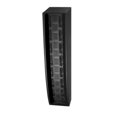
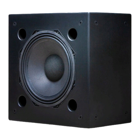
The Christie Vive Audio LS1/LS2 Line Source speakers are designed for screen channel or corner
surround use in small to medium sized auditoriums.
Hardware attachment points on each speaker allow for multiple installation options. They are four-
way, bi-amplified type, with separate inputs for low-frequency and mid-high frequency and require the
use of an electronic crossover and two separate amplifier channels.
A LS1 speaker
B LS2 speaker
Christie Vive Audio LS1/LS2 Line Source Speakers User Manual 4
020-102170-01 Rev. 1 (06-2016)
Copyright © 2016 Christie Digital Systems USA Inc. All rights reserved.

Safety and warning guidelines
Read all safety and warning guidelines before installing, operating, or maintaining the speakers.
Installation safety
The following guidelines apply when installing the speakers.
Warning! Failure to comply with the following could result in death or serious injury.
• Before installation, inspect all components for cracks, deformations, corrosion, and missing or
damaged parts that could reduce their installation strength.
• A minimum of two people or appropriately rated lift equipment is required to safely lift, install,
or move the product.
• The supporting structure must safely support the combined load of the product, all attached
hardware, and components following all local safety standards and regulations.
• Always install all legally required safety straps or cables.
• Install the minimum number of rigging wires required to suspend the speaker.
• Observe load ratings and applicable local safety codes.
• FIRE AND SHOCK HAZARD! Use only the attachments, accessories, tools, and replacement parts
specified by Christie.
Caution! Failure to comply with the following could result in minor or moderate injury.
• FIRE HAZARD! Do not install near any devices that produce heat such as amplifiers, radiators,
heat registers, or stoves.
• Christie products must be installed and serviced by Christie qualified technicians.
Notice. Failure to comply with the following may result in property damage.
• Always turn off and disconnect the amplifiers from power before making audio connections or
servicing a speaker.
Operation safety
The following guidelines apply when operating the speakers.
Caution! Failure to comply with the following could result in minor or moderate injury.
• To prevent permanent hearing loss, ear protection (ear plugs, canal protectors, or ear muffs)
must be worn when operating the amplification system.
• Do not expose the product to moisture.
• Do not place objects containing liquids on the product.
Notice. Failure to comply with the following may result in property damage.
• Speakers exposed to extremely low temperatures must be allowed to warm for a minimum of
one hour before playing them at typical application levels.
Introduction
Christie Vive Audio LS1/LS2 Line Source Speakers User Manual 5
020-102170-01 Rev. 1 (06-2016)
Copyright © 2016 Christie Digital Systems USA Inc. All rights reserved.

Maintenance safety
The following guidelines apply when maintaining the speakers.
Caution! Failure to comply with the following could result in minor or moderate injury.
• Only clean the components with Christie approved products.
Notice. Failure to comply with the following may result in property damage.
• Always turn off and disconnect the amplifiers from power before making audio connections or
servicing a speaker.
• Any changes to the product not approved by Christie will void the warranty.
Permissible sound pressure level limits
Exposure to extremely high noise levels may cause permanent hearing loss.
Individuals vary considerably in their susceptibility to noise-induced hearing loss, but nearly everyone
will lose some hearing if exposed to intense noise for a sufficient length of time.
Earplugs or protectors to the ear canals or over the ears must be worn when operating this
amplification system to prevent permanent hearing loss, if exposure is in excess of the following
permissible limits provided by the United States Occupational Safety and Health Administration
(OSHA):
Duration (consecutive) Sound level (dbA), slow responses
8 hrs 90
6 hrs 92
4 hrs 95
3 hrs 97
2 hrs 100
1.5 hrs 102
1 hr 105
30 min 110
≤15 min 115
Cleaning products
Clean the speaker components with the following Christie approved products.
• Clean, dry, microfiber cloth
Included components
This table lists the components that are shipped with the Vive Audio LS1/LS2 speakers.
Quantity Description Part number
1 LS1 speaker, BKT-LSX tilt bracket 145-170109-XX
Introduction
Christie Vive Audio LS1/LS2 Line Source Speakers User Manual 6
020-102170-01 Rev. 1 (06-2016)
Copyright © 2016 Christie Digital Systems USA Inc. All rights reserved.

Quantity Description Part number
or
1 LS2 speaker, BKT-LSX tilt bracket 145-172101-XX
Introduction
Christie Vive Audio LS1/LS2 Line Source Speakers User Manual 7
020-102170-01 Rev. 1 (06-2016)
Copyright © 2016 Christie Digital Systems USA Inc. All rights reserved.

Installation
Complete the following procedures to install the speaker.
All images shown in the installation instructions are of the LS1 speaker; however, these instructions are
identical for the LS2 speaker.
Mounting the speakers on a platform
Use the BKT-LSX tilt bracket to install the speaker on a platform. The tilt bracket is included in the box
with the speaker.
The instructions provided are for mounting the speaker to the platform in a vertical position. To mount
the speaker horizontally, contact Christie Technical Support.
Positioning the speaker behind a perforated screen
When installing speakers behind a perforated projection screen, the optimal distance from the top-
front of the speaker to rear of projection screen is 150 mm (6 inches) once the laser alignment
procedure is complete. This distance provides the best possible speaker performance behind a
perforated screen.
If this distance is not practical due to site conditions, maintain a distance of no less than 100 mm (4
inches) and no more than 300 mm (12 inches) between the top-front of the speaker and rear of the
perforated screen, to avoid deterioration of audio performance.
Christie Vive Audio LS1/LS2 Line Source Speakers User Manual 8
020-102170-01 Rev. 1 (06-2016)
Copyright © 2016 Christie Digital Systems USA Inc. All rights reserved.

Securing the speaker to the platform with a forward tilt
If you have determined that the speaker should be platform mounted tilted forward, complete this
procedure.
Laser alignment is required when installing this speaker.
For detailed laser alignment instructions, refer to Vive Audio Line Array and Line Source Laser
Alignment Procedures (020-101406-XX) (https://www.christiedigital.com).
1. Remove the four flat head M10 bolts from the bottom corners of the speaker and keep the
bolts for use later.
2. Remove the two fixed and two adjustable bracket plates from the speaker packaging.
Installation
Christie Vive Audio LS1/LS2 Line Source Speakers User Manual 9
020-102170-01 Rev. 1 (06-2016)
Copyright © 2016 Christie Digital Systems USA Inc. All rights reserved.

A Adjustable plate
B Fixed plate
3. Loosely attach the fixed bracket plates to the bottom of the speaker, placing the bolts
removed in step 1 into the left-front and right-front holes.
4. Position an adjustable plate along the bottom edge of the speaker, in front of the right-rear
hole.
5. Using two people and a laser alignment tool, determine the appropriate tilt required.
6. Line up the hole in the speaker with the nearest numbered hole in the adjustable plate.
Each numbered hole represents the angle (in degrees) that the speaker is tilted when secured
in that position.
7. Loosely attach the adjustable bracket plate to the bottom of the speaker, placing the bolt
removed in step 1 into the hole.
8. Repeat steps 5 and 6 on the left-rear side of the speaker.
Ensure that when you attach the left-rear adjustable bracket plate, you are using the same
tilt angle and numbered hole as the right-rear adjustable bracket plate.
Installation
Christie Vive Audio LS1/LS2 Line Source Speakers User Manual 10
020-102170-01 Rev. 1 (06-2016)
Copyright © 2016 Christie Digital Systems USA Inc. All rights reserved.

9. Ensuring that the bottom of the brackets are parallel to the platform, tighten the bolts on
both adjustable bracket plates to the torque of 2.1 N*m (19 in*lbf), securing them to the
speaker.
10. Using a laser alignment tool and the document referred to in step 5, adjust the horizontal aim
of the speaker.
11. Tighten the bolts on both fixed bracket plates to the torque of 2.1 N*m (19 in*lbf), securing
them to the speaker.
Ensure that the bottom of the brackets are parallel to the platform.
12. Secure the adjustable bracket plates to the platform using appropriately sized lag bolts (not
provided in the box) according to laws and regulations applicable to the venue.
13. Secure the fixed bracket plates to the platform using appropriately sized lag bolts (not
provided in the box) according to laws and regulations applicable to the venue.
Securing the speaker to the platform with a backwards tilt
If you have determined that the speaker should be platform mounted tilted backwards, complete this
procedure.
Laser alignment is required when installing this speaker.
For detailed laser alignment instructions, refer to Vive Audio Line Array and Line Source Laser
Alignment Procedures (020-101406-XX) (https://www.christiedigital.com).
1. Remove the four flat head M10 bolts from the bottom corners of the speaker.
2. Remove the two fixed and two adjustable bracket plates from the speaker packaging.
A Adjustable plate
B Fixed plate
3. Loosely attach the fixed plates to the bottom of the speaker, placing the bolts removed in step
1 into the left-rear and right-rear holes.
Installation
Christie Vive Audio LS1/LS2 Line Source Speakers User Manual 11
020-102170-01 Rev. 1 (06-2016)
Copyright © 2016 Christie Digital Systems USA Inc. All rights reserved.

4. Position an adjustable plate along the bottom edge of the speaker, in front of the right-front
hole.
5. Using two people and a laser alignment tool, determine the appropriate tilt required.
6. Line up the hole in the speaker with the nearest numbered hole in the adjustable plate.
Each numbered hole represents the angle (in degrees) that the speaker is tilted when secured
in that position.
7. Loosely attach the adjustable bracket plate to the bottom of the speaker, placing the bolt
removed in step 1 into the hole.
8. Repeat steps 5 and 6 on the left-front side of the speaker.
Ensure that when you attach the left-front adjustable plate, you are using the same tilt angle
as the right-front adjustable plate.
9. Ensuring that the bottom of the brackets are parallel to the platform, tighten the bolts on
both adjustable bracket plates to the torque of 2.1 N*m (19 in*lbf), securing them to the
speaker.
Installation
Christie Vive Audio LS1/LS2 Line Source Speakers User Manual 12
020-102170-01 Rev. 1 (06-2016)
Copyright © 2016 Christie Digital Systems USA Inc. All rights reserved.

10. Using a laser alignment tool and the document referred to in step 5, adjust the horizontal aim
of the speaker.
11. Tighten the bolts on both fixed plates to the torque of 2.1 N*m (19 in*lbf), securing them to
the speaker.
Ensure that the bottom of the brackets are parallel to the platform.
12. Secure the adjustable bracket plates to the platform using appropriately sized lag bolts (not
provided in the box) according to laws and regulations applicable to the venue.
13. Secure the fixed bracket plates to the platform using appropriately sized lag bolts (not
provided in the box) according to laws and regulations applicable to the venue.
Flying the speaker vertically
The speaker is flown, according to installer best practices, using four rigging cables and any legally
required redundant safety cables.
Flying a speaker should only be done by qualified rigging professionals in accordance with local
requirements and regulations.
1. Place the speaker on a flat stable surface in a vertical position.
2. Remove the four pre-installed M10 x 60 mm flat head bolts from the top of the speaker.
3. Insert and screw in the four eye-bolts.
If more downward tilt of the speaker is required, remove two flat head bolts from the top-front
of the speaker, and two from the bottom-rear of the speaker, and insert the eye-bolts into
these holes.
4. Attach the rigging cables to the eye-bolts.
Installation
Christie Vive Audio LS1/LS2 Line Source Speakers User Manual 13
020-102170-01 Rev. 1 (06-2016)
Copyright © 2016 Christie Digital Systems USA Inc. All rights reserved.

5. Hang the speaker.
Flying the speaker horizontally
The speaker is flown, according to installer best practices, using four rigging cables and any legally
required redundant safety cables.
Flying a speaker should only be done by qualified rigging professionals in accordance with local
requirements and regulations.
1. Place the speaker on a flat stable surface on its back.
2. Remove the 24 M5 screws and lock washers from the waveguide.
3. Carefully pull the waveguide away from the cabinet, making sure to not strain the connecting
wires.
4. Rotate the waveguide 90 degrees clockwise.
5. Insert the waveguide into the cabinet.
6. Secure the waveguide with the 24 screws and lock washers removed in step 1.
7. Turn the cabinet horizontally.
8. Remove the four pre-installed M10 flat head bolts from the top of the speaker.
9. Insert and secure the four eye-bolts.
Installation
Christie Vive Audio LS1/LS2 Line Source Speakers User Manual 14
020-102170-01 Rev. 1 (06-2016)
Copyright © 2016 Christie Digital Systems USA Inc. All rights reserved.

If more downward tilt of the speaker is required, remove two flat head bolts from the top-front
of the speaker, and two from the bottom-rear of the speaker, and insert the eye-bolts into
these holes.
10. Attach the rigging cables to the eye-bolts.
11. Hang the speaker.
Connecting the speaker wires
Once the speaker is installed, connect the speaker wires to the amplifier.
Notice. Failure to comply with the following may result in property damage.
• Always turn off and disconnect the amplifiers from power before making audio connections or
servicing a speaker.
1. These speakers are bi-amped, with distinct negative and positive input terminals for the low
frequency and mid/high frequency sections. Connect the separate low frequency and mid/
high frequency speaker wires to the negative (A) and positive (B) terminals on the back of
the speaker.
if creating crimped spade lug terminations, use a #8 spade lug (P/N: 145-159106-XX).
Installation
Christie Vive Audio LS1/LS2 Line Source Speakers User Manual 15
020-102170-01 Rev. 1 (06-2016)
Copyright © 2016 Christie Digital Systems USA Inc. All rights reserved.

A Negative (-) connections
B Positive (+) connections
2. Connect the speaker wires to the corresponding terminals on the amplifier for both the low
frequency and mid/high frequency sections.
3. Turn on the amplifier and verify that the speaker is receiving an input signal by playing a test
signal through the system.
Ensure that the amplifier attenuators or gain controls are at nominal settings.
Installation
Christie Vive Audio LS1/LS2 Line Source Speakers User Manual 16
020-102170-01 Rev. 1 (06-2016)
Copyright © 2016 Christie Digital Systems USA Inc. All rights reserved.

Troubleshooting
For assistance with common issues, refer to the following troubleshooting topics.
If you cannot resolve your issue with the information provided, contact Christie Technical Support.
The speaker does not function
The speaker is connected to the amplifier, but is not producing any sound.
Resolution
• Verify that the speaker is receiving an input signal from the amplifier.
• Verify that the circuit breaker for the main circuit to the amplifier is closed.
• Verify that amplifier is powered on and attenuators or gain controls are at nominal settings.
• If open, reset the circuit breaker. If the AC mains breaker continues to open, check the voltage
and amperage of the circuit.
• Verify that the speaker wires are correctly connected to the input terminals on the speaker and
the terminals on the amplifier.
The speaker sound is degraded
The speaker is receiving a signal and sound is being output, but it is distorted.
Resolution
• Visually inspect the speaker for deterioration or holes.
• Ensure that the input signal to the amplifier is clean.
• Verify that attenuators or gain controls on amplifies and any audio processors are at nominal
settings.
• Verify that the speaker wires from the speaker are securely connected to the terminals on the
amplifier.
• Verify that the speaker wires are correctly connected to the input terminals on the speaker.
• Verify there are no loose or missing screws. Replace all screws you removed during
installation.
• Have an authorized dealer complete an audio test (for example, pink noise, frequency sweeps,
and content and program material).
Christie Vive Audio LS1/LS2 Line Source Speakers User Manual 17
020-102170-01 Rev. 1 (06-2016)
Copyright © 2016 Christie Digital Systems USA Inc. All rights reserved.

There is audible noise from speaker
The speaker is producing audible noise when the amplifier driving it is powered on.
Resolution
• Mute channels, one at a time, to isolate the problem.
• Verify that all line-level cables in the signal chain are in good condition.
• Ensure that the input signal to the amplifier is clean.
• Reroute audio cables away from AC power and lighting cables.
• Verify the correct gain structuring of B chain, input levels, and output levels of source devices
and amplifiers.
Troubleshooting
Christie Vive Audio LS1/LS2 Line Source Speakers User Manual 18
020-102170-01 Rev. 1 (06-2016)
Copyright © 2016 Christie Digital Systems USA Inc. All rights reserved.

Specifications
Learn about the product specifications. Due to continuing research, specifications are subject to
change without notice.
Audio
Learn about the audio specifications.
Specification LS1 description LS2 description
System type Four-way, bi-amp, vented enclosure.
Driver components High-frequency: 2 x 3 in. planar ribbon
driver with Kapton diaphragms and
Neodymium magnets.
Mid-frequency: 6.5 in. cone driver with 38
mm voice coil.
Low-frequency: 15 in. paper composite cone
driver with 100 mm diameter voice coil.
High-frequency: 6 in. and 3 in. planar
ribbon drivers with Kapton diaphragms and
Neodymium magnets.
Mid-frequency: 6.5 in. paper/Kevlar cone
high efficiency Neodymium magnet driver
with 51 mm voice coil.
Low-frequency: 2 x 15 in. paper composite
cone drivers with 100 mm diameter voice
coils.
Crossover¹Low-frequency and mid-frequency: 350 Hz,
active via processor.
Mid-frequency and high-frequency: passive
at 2.0 kHz. Two-way high-frequency section
with frequency shading network.
Low-frequency: 350 Hz active via processor.
Mid-frequency and high-frequency: Passive
in mid- and high-frequency section with 2
kHz and 7 kHz crossover points. Two-way
high-frequency section with frequency
shading network.
Frequency response230 Hz-20 kHz at -6dB
Maximum SPL3Low-frequency: 122.8 dB continuous, 125.0
dB IEC maximum long term, 126.8 dB IEC
maximum short term.
Mid-frequency and high-frequency: 123.1
dB continuous, 124.4 dB IEC maximum long
term, 126.1 dB IEC maximum short term.
LS1 system: 126.0 dB continuous, 127.7 dB
IEC maximum long term, 129.5 dB IEC
maximum short term.
Low-frequency: 128.8 dB continuous, 131.1
dB IEC maximum long term, 132.8 dB IEC
maximum short term.
Mid-frequency and high-frequency: 124.3
dB continuous, 126.5 dB IEC maximum long
term, 128.0 dB IEC maximum short term.
LS2 system: 130.0 dB continuous, 132.4 dB
IEC maximum long term, 134.0 dB IEC
maximum short term.
System coverage4100° horizontal dispersion , 40° vertical dispersion.
Sensitivity1, 1 W/1 m Low-frequency: 95.0 dB. Low-frequency: 98.0 dB.
Christie Vive Audio LS1/LS2 Line Source Speakers User Manual 19
020-102170-01 Rev. 1 (06-2016)
Copyright © 2016 Christie Digital Systems USA Inc. All rights reserved.

Specification LS1 description LS2 description
Mid-frequency and high-frequency: 101.3
dB.
Mid-frequency and high-frequency: 102.5
dB.
Recommended
amplifier power
Low-frequency: 600-1000 W at 8 ohms.
Mid-frequency and high-frequency: 200-300
W at 6 ohms.
Low-frequency: 850-1500 W at 8 ohms.
Mid-frequency and high-frequency: 350-450
W at 8ohms.
Rated impedance Low-frequency: 8 ohms.
Mid-frequency and high-frequency: 6 ohms.
Low-frequency: 4 ohms.
Mid-frequency and high-frequency: 8 ohms.
1For more detailed crossover information, see Recommended Crossover Settings (P/N 020-101405-01)
(https://www.christiedigital.com).
2Measured at 2 m on tweeter axis in simulated free field conditions. Sensitivity is calculated based on
measured SPL response averaged in 200 Hz-5 kHz range.
3IEC refers to IEC 60268-5 standard. Maximum SPL values calculated based on sensitivity and IEC
power ratings. Continuous power handling tested using IEC60268-1 noise signal for duration of two
hours.
4Averaged in the 500 Hz-12 kHz range, at -6 dB.
Power requirements
Learn about the power specifications.
Specification LS1 description LS2 description
Power handling
capacity1
Low frequency: 600 W continuous, 1000 W
IEC long term, 1500 W IEC short term.
Mid-frequency and high-frequency: 150 W
continuous, 200 W IEC long term, 300 W
IEC short term.
Low frequency: 1200 W continuous, 2000 W
IEC long term, 3000 W IEC short term.
Mid-frequency and high-frequency: 150 W
continuous, 250 W IEC long term, 350 W
IEC short term.
1IEC refers to IEC 60268-5 standard. Maximum SPL values calculated based on sensitivity and IEC
power ratings. Continuous power handling tested using IEC60268-1 noise signal for duration of two
hours.
Physical
Learn about the physical specifications.
Specification LS1 description LS2 description
Input connectors Four position terminal barrier strip with separate low-frequency and mid/high-frequency
inputs.
Enclosure • Vented enclosure with a tuning frequency of 32 Hz (LS1) or 28 Hz (LS2)
•18 mm marine plywood, heavily braced for maximum structural strength and
minimum panel resonance
• Rotatable mid/high-frequency section in acoustically isolated enclosure
Specifications
Christie Vive Audio LS1/LS2 Line Source Speakers User Manual 20
020-102170-01 Rev. 1 (06-2016)
Copyright © 2016 Christie Digital Systems USA Inc. All rights reserved.
This manual suits for next models
1
Table of contents
Other Christie Speakers manuals

Christie
Christie LA4 User manual

Christie
Christie Vive Audio LA3i User manual

Christie
Christie LA4S User manual

Christie
Christie LA5C User manual

Christie
Christie LA3S User manual

Christie
Christie Vive Audio LA3Si User manual

Christie
Christie Vive Audio LA3 User manual

Christie
Christie Vive Audio LA5 User manual

Christie
Christie LS3S User manual

Christie
Christie LA3S User manual