T-Storm TS 120CC Slick User manual

Instruction Manual for TS 120CC Slick/Edge/Extra

Table of Contents
Introduction & Disclaimer
Tools and components required for assembly
Assembly tips
Elevators
Wings
Rudder
oHorn installation
oOption 1 – Push/Pull setup
oOption 2 –Pull/Pull setup
Under Carriage
oTail wheel assembly & installation
oMain landing gear installation
Fuselage
Setup
1

Introduction
Congratulations on your purchase of the new TS 120cc Edge/Slick/Extra.
Hailing from the pioneering factory of leading aerobatic models, the TS 120cc Edge/Slick/Extra has been
specifically designed and developed to cover all aspects of aerobatic flight.
With extensive design work the TS 120cc Edge/Slick/Extra. has been developed to be a strong yet light
weight aircraft that is precise for your IMAC schedules, superior in stalled/ high alpha flight and
capable of performing the very latest extreme 3D aerobatic manoeuvres.
We are sure that the TS 120cc Edge/Slick/Extra, which has been jointly designed by T Storm Hobby,
will provide you with many hours of exhilarating flights.
Please be sure to read this manual thoroughly before assembly to familiarise yourself with the parts
and fittings. We suggest that a complete dry fit of the model is performed prior to assembly to
check for correct fit.
TS 120cc Edge/Slick/Extra kit includes good quality servo hardware, cable ties, velcro straps, pre-installed
extension leads for the elevators, pre-installed rudder pull/pull cables, spare extension leads for a
rudder push/pull setup, 5”carbon spinner, carbon under carriage, carbon wing and stabiliser tubes.
Padded wing and stabiliser bags complete the quality accessories.
The included canister holders that suit a range of different brands allow you to install the best
combination of silencers to suit the engine of your choice.
Two sets of stabilisers are included, a ‘3D’ set with counter balances and an ‘IMAC’ set without
counter balances. This allows you to choose an elevator arrangement to suit your flying style.
Whilst every care has been taken to ensure that the model reaches you in perfect condition,
sometimes mishaps can happen during transit. If you find anything wrong with the model upon
receipt, please contact the distributor immediately.
DISCLAIMER: -
THIS MODEL IS NOT A TOY.
If it is misused it can cause serious bodily harm or even death and damage to property. This model is
designed for high performance, and as such T Storm Hobbies provide high quality components with
the kit. If you have any doubts about the assembly of this model, please seek advice from an
experienced modeller.
The packaging contains small items; please keep small children away when assembling the model.
Please use the recommended equipment when assembling this model.
For safety reasons please comply with your club rules or rules as set out by your governing body.
Please read and understand this manual prior to, and refer to it often during assembly, do not
deviate from the established construction method.
T Storm Hobbies cannot accept any responsibility or liability resulting in any damaged caused from
the use of this model.
2

Tools and components required for assembly
To complete the TS 120cc Edge/Slick/Extra you will require the following tools: -
Hobby knife with a selection of sharp blades
Electric drill & various drill bits
Covering iron/heat gun
Needle files
Adjustable spanner
Small flat head and Philips screwdrivers
Allan keys/drivers (1.5/2.5/3/4mm)
Sandpaper and block
Pliers
Various sockets (optional)
Ruler and Calliper gauge
Various adhesives: -
5 minute epoxy
30 minute
epoxy
Thin and
medium Cyano
Silicon sealant
Blue Loctite
Isopropanol alcohol
Hardware components required: -
100 – 120cc engine with mufflers/canisters/tuned pipes to suit
Propeller to suit your engine
9 high torque digital standard sized servos (HV recommended)
o4 servos minimum are required for the ailerons (6 optional, 3 per aileron)
o2 servos are required for the elevators
o2 servos are required for the rudder
o1 servo is required for the throttle
Servo arms: -
o6no 1.75” arms for ailerons and elevators (8no if 3 servos/wing setup used)
o2no 2” arms for a push/pull rudder setup*
o1no 1.75” single and 1 no 3.5” double arm for a pull/pull rudder setup*
o*See the Rudder section of the manual for in depth details of these options
1no 1 litre fuel tank
1no Fuel dot
1m Tygon or similar fuel
tube Radio gear
Ignition and receiver batteries
Spinner bolt to suit your
engine

3

Assembly Tips
Before starting work on the model, inspect the fuselage, wings, stabilisers, rudder and the
under carriage for any damage/defects.
If possible, do a dry fit of the major components to check the fit.
Use the covering iron or heat gun to shrink out any wrinkles that may have developed
during transit from the factory.
oThe 120cc Extra/Slick/Edge is covered with state of the art printed covering material that has
been lacquered to protect the ink. When using an iron to remove any wrinkles, we
recommend that the iron is not set at really high heat otherwise the lacquer may
melt onto your irons hotplate. (The builder found temperatures of between 140oC
and 155oC gave the best results). A loose fitting sock on the iron will also help when
rubbing around the servo cut-outs.
When gluing the horns in on the surfaces, use Isopropanol alcohol on a kitchen towel to
remove the excess glue.
Keep an eye on the horns for the first 30 minutes after gluing them in place to ensure that
they do not move. This is important for the geometry of the servo linkages and will ensure
that you end up with identical setups across corresponding surfaces.
Let’s start the build…
4

Elevators
Locate the elevator fittings bag from the accessories box. It will contain the items as shown in the
image below: -
Take the horns and back plates and rough up the surfaces with rough sandpaper. This will provide
the glue with a key when it is installed in the elevator.
Repeat this process for all the horns and back plates.
Locate the horn positions on the elevator, they are pre-cut. Use your iron to apply heat to the area
around the slots to really stick the covering to the wood beneath.
5

Enlarge the slot in the covering to allow the horn assembly to be dry fitted.
Tip: - If the horn assembly is a tight fit, insert one horn into a slot and ‘work’ it back a forth, and in and
out to loosen the hole. If necessary, use a small needle file to remove any stubborn excess glue. Repeat
this process for the other slot.
Now draw around the horn back plate and remove the horn assembly.
Carefully cut inside the mark you have just drawn with your hobby knife. Take care not to press too
hard with the knife; you only want to cut through the covering, not into the wood. Clean off the ink
using alcohol.
6

Mix up some 30 minute epoxy and liberally coat the insides of both slots and the horn assembly.
Insert the horn assembly and push in firmly, remove the excess epoxy with alcohol and a clean
kitchen towel.
Insert a 3mm bolt through the horns to keep them aligned whilst the epoxy cures.
Tip: - Use the bolt to line the holes in the horns up with the hinge line of the elevator.
7

Make up the servo pushrods using the turnbuckles and ball links as shown. Use the spanner found in
the spares bag in the accessories box to help.
Note: - There are two types of ball links in the hardware bag, one with a base on the brass ball and one
without. Be sure to install one of each type onto the turnbuckle. The end with the base is for the servo
arm end, the other end goes between the horns.
Tip: - Apply a little oil to the ball link to ease the insertion of the thread of the turnbuckle.
SERVO
END
HORN
END
The stabiliser has the servo holes pre-drilled for you. Carefully drop some thin cyano into the holes
to harden the plywood. Install the servo, then a 1.75” servo arm using the hardware that came with
the servo.
Attach the pushrod to the horn and arm using the supplied bolts, washers and nuts.
Tip: - apply a drop of blue threadlok to the nut end of the bolt to add some added security against the
nut coming undone.
Repeat the above steps for the other elevator.
8

Wings
Locate the aileron fittings bag from the accessories box. It will contain the items as shown in the
image below: -
Note: - If you wish to use the 3 servo per wing option, there is an extra set of horns and back plates in
the spares bag in the accessories box.
Take the horns and back plates and rough up the surfaces with rough sandpaper. This will provide
the glue with a key when it is installed in the aileron.
Repeat this process for all the horns and back plates.
Note: - Decide how many servos you will be using per wing now so that you can cut out the
corresponding area on the wing panel. In this build we are using two servos per wing. We have cut out
the holes closest to the wing root and the wing tip. The third servo location hole is in the centre of the
wing panel.
As we did with the elevators, cut the covering to expose the slots below. Use a single horn to
widen/loosen the wood and, if necessary, use a needle file to remove any excess stubborn glue.
9

Insert the horn assembly and draw around the base plate.
Remove the horn assembly and again, carefully cut inside the drawn lines, leaving about 2mm
clearance. Clean the area with alcohol.
Mix up some 30 minute epoxy and liberally coat the insides of both slots and the horn assembly, as
we did with the elevator slots and horns.
10

Insert the horn assembly and push in firmly, remove the excess epoxy with alcohol. Don’t forget to
add the 3mmm bolt to keep the horns in line.
When the glue on the horns has dried sufficiently, you can start to cut out for the servos.
Locate the holes that you will be using and carefully cut the covering away to expose the servo
support beneath. Insert a servo into each hole and, using a small drill bit, drill pilot holes for the
servo screws. Remove the servos and add a drop of thin cyano to the holes to harden the plywood.
You can see the strings that the factory has pre-installed to help you pull your servo wires through
to the wing root. Remove the string and feed it through the servo wire next to the servo plug as
shown.
11
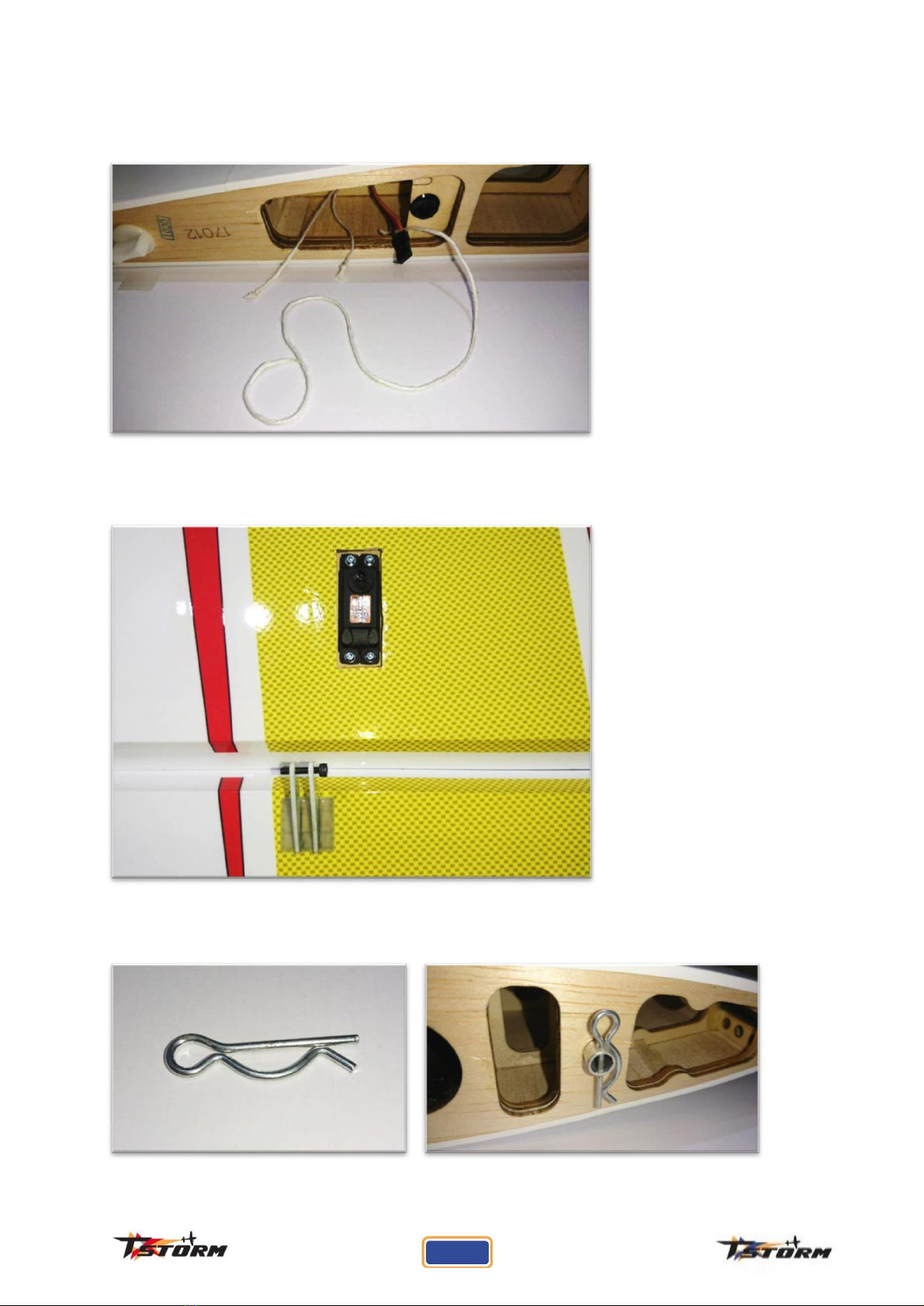
Pull the string from the wing root and carefully draw the servo wire through, take care not to catch
the plug on any of the wing ribs. Repeat this process for the other servos.
A completed servo bay is shown below for reference, notice that the bolt is directly above the hinge
line.
Locate the split pin and install it onto the aluminium peg on the wing root.
12

Make up the servo pushrods using the turnbuckles and ball links as shown. Use the spanner found in
the spares bag in the accessories box to help.
Note: - There are two types of ball links in the hardware bag, one with a base on the brass ball and one
without. Be sure to install one of each type onto the turnbuckle. The end with the base is for the servo
arm end, the other end goes between the horns.
Tip: - Apply a little oil to the ball link to ease the insertion of the thread of the turnbuckle.
SERVO
END
HORN
END
Centre your servo and install a 1.75” servo arm using the hardware supplied with your servo. Using
the bolts, washers and nuts supplied, attach the pushrod to the horn and servo arm as shown below.
Tip: - Although the nut has a nyloc insert, apply some blue threadlok to the nut end of the bolt for
added security.
Repeat for the other servo.
Repeat these steps for the other wing.
13

Fuselage
Before starting to fit your engine or radio equipment into the fuselage, take a few minutes to apply
thin cyano to the tabs and slots in the plywood construction. This will considerably stiffen the
fuselage, and fill any gaps that may have been missed during construction in the factory.
Locate the power fixings hardware bag in the accessories box, the contents will be as follows: -
You will find a range of templates for mounting your engine in the accessories box too.
14

Tip: - To assist the engine installation, temporarily fit the undercarriage legs.
Choose the template that most closely matches your engine and line the laser etched lines with
those on the firewall, and clamp in place.
Tip: - Cut notches from the template edges to allow you to clearly see the lines on the firewall.
Now, using an electric drill, drill a hole through one of the top holes of the template and through the
firewall.
Mark the positions of the other 3 holes, but DO NOT DRILL THEM AT THIS STAGE.
Note: - Only drilling one hole makes it much easier to adjust how the engine is centred in the cowl,
should you need to.
15

Take your engine and temporarily bolt it to the firewall using a bolt, a stand-off and a washer
supplied in the hardware pack. Use another stand-off to support the opposite corner of the engine's
back plate. Remove the cowl bolts from the front of the fuselage and offer up the lower half of the
cowl to check the how well it is centred.
Make adjustments to the hole that you have drilled and check the fit again. Once satisfied with the
fit, put the top half of the canopy on and recheck using the spinner as a reference. Ideally you want
equal spacing around the whole circumference of the spinner back plate. Also check the clearance
between the back plate and the front of the cowl. Adjust with washers behind the stand-off as
necessary.
16

Once you are completely satisfied with the test fit, use the template to drill the remaining three
holes and fit your engine properly.
Note: - We have used 5 minute epoxy to fix some 18mm triangle stock around the motor box and ‘F1’.
This is optional and not a requirement.
Attach the motor box cover, found in the accessories box, using four of the M3 bolts and washers.
Add a drop of blue threadlok to the bolts for added security.
Now you can fit your ignition unit in your preferred manner. The following images can be used as
examples.
17

Locate one of the servo hole ‘doublers’ from the accessory box, and glue it on the inside of the
motor box to help with the throttle servo screw support.
Drill a hole through the firewall for your carburettor feed line from the fuel tank, and run the tube
through it.
Now also install your headers and canisters (if you are using them).
Select the canister support from the accessories box that best meets your requirements. Use the
included silicone tube segments to support the canisters in the mount.
There are fixing points with captive nuts within the canister tunnel, use M3 bolts and washers with
blue threadlok to secure them. (The one shown is just in front of the under carriage mounting
block).
18
This manual suits for next models
2
Table of contents
Popular Toy manuals by other brands

Rapido Trains
Rapido Trains Amtrak NPCU F40PH Operator's manual

Rapido Trains
Rapido Trains F59PH Operator's manual

SCALE-PARKFLYER
SCALE-PARKFLYER DC 3 Fatty Building instructions

Cranium
Cranium Turbo Rocket Pack instructions

Bengtson Company
Bengtson Company FOKKER EIII instructions

Reely Sky
Reely Sky Redskin operating instructions


