4max Inspiration F3A 50E User manual

4-Max Inspiration F3A, 50e Assembly Instructions
www.4-Max.co.uk
Specifications
Class 50e
Type F3A
Material EPO Foam
Wingspan 1380mm / 54.33”
Length 1480mm / 58.26”
Flying Weight 1950g / 4.3lbs (inc 4S 3700mAh battery)

Many thanks for purchasing the 4-Max Inspiration F3A 50E Kit from 4-Max Models.
We hope you enjoy your new model.
At 4-Max Models, we like to offer competitive prices, good performance, and products that you
can setup and use with ease. That’s why we have extensively researched and tested this
airplane and suggested all the products necessary for you to have a great performing aircraft.
By purchasing and/or building this model, the user assumes ALL liability and risk involved with
this product. This model should be built and flown by an experienced builder and R/C Flyer.
4-Max Models guarantees this model to be free of defects at the date of purchase. This
warranty does not cover any parts damaged by use, modification or crash damage.
In no way shall 4-Max Models’ liability exceed the original cost of the purchased model.
Further, 4-Max Models reserves the right to modify this warranty without notice. 4-Max Models
has no control over the final stages of assembly or the materials/glue used for the final
assembly.
By the act of using the final product the user accepts all resulting liability.
4-Max Models, as an R/C supplier provides a top-quality model and instructions to complete
the model. The quality and flight characteristics of the finished model will depend greatly on
how it is built. We cannot guarantee the performance for the completed model and
representations are expressed or implied as to the performance of the completed model.
If the buyer is not prepared to accept the liability associated with the use of this product, the
buyer is advised to return this kit immediately, in new and unused condition for a full refund.
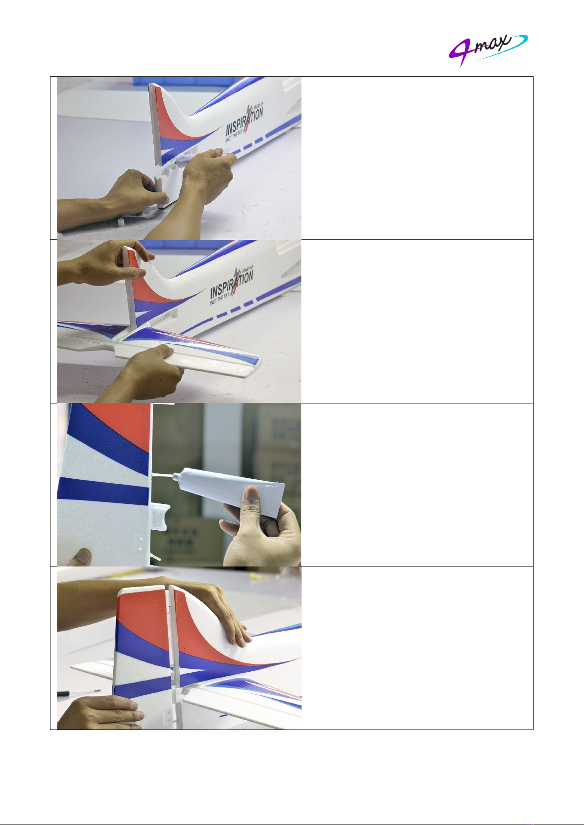
Safety in Assembly
During assembly of this airplane, you will need to use sharp knives and glues. Please follow all
safety procedures recommended by the manufacturers of the products you use, and always
follow these important guidelines: ALWAYS protect yourself when working with adhesives,
knives, or tools. Safety glasses are advised to protect your eyes.
Safety in Flying
This is NOT a toy! It is a high-performance R/C model capable of high speeds and extreme
manoeuvres. It should only be operated by a competent R/C pilot in a safe area with proper
supervision. ONLY fly your airplane in a safe, open area, away from spectators and vehicles–
and where it is legal to fly. Never run your motor inside a house or building with the propeller
attached – Remove the prop for safety. Never run the motor on the ground at full or near full
throttle for more than 20 seconds. We recommend you get insurance from the BMFA.
Required Items
Brushless Motor Recommended 4-Max PO-3547-800
Brushless ESC Recommended 4-Max 4M-ESC50A
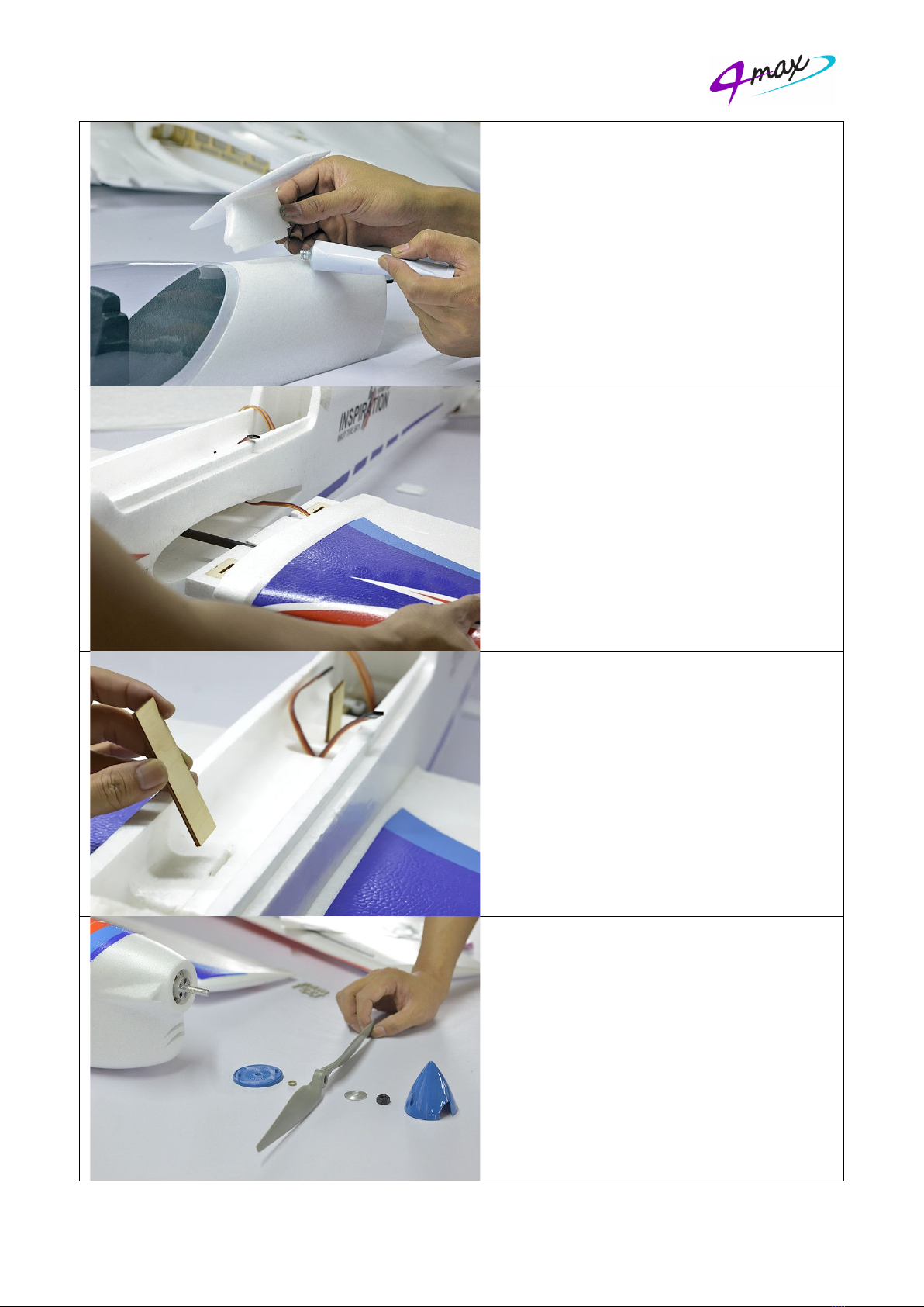
Propeller Recommended 4-Max JXF 13x6
4x Servo Recommended Emax ES3001
Servo Extension Leads 4x 200mm, 2 x100mm
Spinner Recommended 4-Max 57mm cooling spinner
Foam Safe Glue Recommended Deluxe Materials Foam 2 Foam
Transmitter and Receiver Minimum 4 channel, 6 is recommended
LiPo Battery 4S, 3700mAh LiPo Minimum 40C, 60C Recommended
Suitable LiPo charger MUST be LiPo compatible
Sharp knife
Set Metric Allen wrenches
Scissors
Small pliers
Wire cutters
Petroleum jelly
All of these items are available from www.4-max.co.uk

Sales@4
-
Before Starting Assembly
Unpack your
items, d
o not do any assembly and
Airframe Parts
1.
1x
2.
1x
3.
1x
4.
1x
5.
1x
6.
2x
7.
1x
8.
2x
9.
1x
10.
Foam safe glue
11.
1x
12.
3x
13.
2x
14.
4x
15.
8x
16.
1x
17.
2x
18.
1x
19.
2x
20.
1x
21.
Spare screws
-
Max.co.uk
Before Starting Assembly
Unpack your
model
o not do any assembly and
Airframe Parts
1x
Fuselage
1x
Right
wing
1x
Rudder
1x
Carbon
fibre
1x
Horizontal stabiliser
2x
Lan
ding gear
1x
Small f
uselage wing
2x
Spats
1x
Lan
ding gear wire
Foam safe glue
1x
Small Philips screwdriver
3x
Pin hinges (rudder)
2x
Push rods with clevises
4x
Control
horn
8x
Control horn screw
1x
Lan
ding gear
2x
Wing fixing plates
1x
Landing gear plate
2x
Wheels
1x
Motor mount
Spare screws
www.4
Before Starting Assembly
model
and examine the
o not do any assembly and
wing
and 1x
left wing
fibre
wing
tube
Horizontal stabiliser
ding gear
covers
uselage wing
ding gear wire
Foam safe glue
(
NOT in kit
Small Philips screwdriver
Pin hinges (rudder)
Push rods with clevises
horn
s
and backing plates
Control horn screw
s
ding gear
retaining
Wing fixing plates
Landing gear plate
Motor mount
ing set
Spare screws
www.4
and examine the
contents
o not do any assembly and
contact
left wing
tube
covers
uselage wing
(canalyzer)
NOT in kit
)
Small Philips screwdriver
Push rods with clevises
and backing plates
s
retaining
set
(“X” mount not included)
www.4
-
Max.co.uk
contents
. If you
contact
4-
Max Models
(canalyzer)
and backing plates
(“X” mount not included)
Max.co.uk
. If you
have any missing or damaged
Max Models
(“X” mount not included)
have any missing or damaged
Max Models
immediately.
Tel: 01256 782 512
have any missing or damaged
immediately.
Tel: 01256 782 512
have any missing or damaged

Step 1
Dry fit the Horizontal stabilizer to the
fuselage and trim/adjust if necessary to get
a good fit.
Step 2
Apply foam safe glue to the top and bottom
of the fuselage opening as per the photo.
Step 3
Slide the horizontal stabilizer in place, make
sure it is square to the fin and fuselage and
allow to dry.
Step 4
Dry fit the rudder to the fin and trim/ adjust
if necessary to get a good fit. Make holes in
rudder for pin hinges.
Step 5
Apply a little petroleum jelly to just the
centre of the pin hinges (to stop the glue
from seizing them up)
Apply foam safe glue to three slots and pin
hinges on the tail of fuselage.
Step 6
Glue the 3 pin hinges in the rudder first,
ensuring the are at the correct angle
Apply glue to the three rudder connectors
and pin hinges, DO NOT apply glue to the
tail wheel wire. Insert into the pre-cut
slot/holes in the rudder. Make sure the tail
wheel wire is also inserted in the rudder
when gluing the rudder on. Ensure no glue is
on the centre part of the pin hinges

Step 7
Secure two servos on the servo plate in the
fuselage using the servo screws supplied
with the servos as per the photo. The holes
are cut for the Emax ES3001 servo. To get
at the rear screws, cut the piece of foam out
at the bottom of the slot for the canopy.
Step 8
Connect the servos to the push rods using
the swing keepers.
Step 9
Secure the white control horn and backing
plate on the elevator with two M2.5 by
16mm long self-tapping screws.
Connect control wire to the servo control
horn on the elevator. Clip the Swing Keeper
in place to stop the wire coming out of the
control horn as per the photo.
Step 10
Repeat for the rudder.
Step 11
Attach the motor to the “X” mount
(supplied)
Step 12
Install the motor assembly on the motor box
using the 10mm spacers (supplied).
Step 13
Install the Prop driver on the motor using
the 4 screws supplied with the motor.

Step 14
Remove any pre-soldered ends of wire and
solder (only using leaded solder) your
connector of choice to the battery side of the
ESC, paying close attention to the polarity.
You will most probably need to extend the
battery wires from the ESC.
Step 15
Attach the ESC to the side or bottom of the
wooden motor mount as per the photo and
connect the 3 wires to the motor.
Step 16
Secure the cowling to the fuselage with four
M2.5 by 25mm long self-tapping screws.
Step 17
Install the wheels on the landing gear wire.
Lock the wheel in place with the supplied
wheel collets.
The wheels should rotate freely, but not be
loose, adjust if necessary.
Step 18
Install the spats to the undercarriage leg
using the two M2.5 by 10mm long screws as
per the photo.
.

Step 19
Trim the landing gear covers to fit with a
sharp knife and secure landing gear foam
covers on the landing gear assembly with
foam safe glue.
Please note that they are handed.
Step 20
Insert the landing gear into the slot on the
bottom of fuselage. Then Insert the landing
gear plate into the slot.
Step 21
Secure the landing gear plate using two
M2.5 by 10mm long self-tapping screws.
Might be a good idea to add a washer (not
supplied)
Step 22
Secure the white control horn and backing
plate on the aileron using two M2.5 by
16mm long self-tapping screws. Ensure the
servo is centred before gluing it in place
using foam safe glue. Connect swing keeper
to the servo. Clip the clevis to the control
horn on the aileron as per the photo.
Attach the servo extension lead to the servo
and either glue or tape in place so they are
flush to the bottom surface of the wing.

Step 23
Install the small fuselage wing (canalyzer) to
the top of the fuselage just behind the
canopy using foam safe glue ensure it is fully
seated and square to the fin and parallel to
the horizontal stabilizer.
Step 23
Install the right and left wing on the fuselage
using the carbon fibre tube supplied. Feed
the servo leads through as per the photo.
Step 24
Insert the two wooden wing locking plates
in to the pre-cut slot in the fuselage.
These lock the wings in place.
Tip: Add a bit of tape to one end of the ply
plates to allow you to remove them once
installed.
Step 25
Install the propeller and cooling Spinner to
the motor. Make sure the propeller spins
freely and doesn’t touch the plastic nose
cone

Step 26
Install your receiver and check all surfaces move in the correct direction.
As you have purchased this model we assume you’re are a competent flyer and are familiar
with this.
Centre of Gravity
The CG should be 135mm from the leading edge of the wing.
Suggested control throws
Measurements taken at the widest part of the moving surface
Elevator: +25mm, -25mm, 30% Exponential
Aileron: +25mm, -25mm, 30% Exponential
Rudder: +45mm, -45mm, 30% Exponential
Don’t forget to range test your model as per the radio manufacturer’s instructions.
We hope you have enjoyed assembling this model and may your take off’s equal your landings.
Table of contents
Other 4max Toy manuals