manuals.online logo
Brands
  1. Home
  2. •
  3. Brands
  4. •
  5. Tacmina
  6. •
  7. Water Pump
  8. •
  9. Tacmina SXDA User manual

Tacmina SXDA User manual

Metering Pumps
SXDA/SXWA/SYDA/SYWA
User's Manual
WARNING
• Install the pump in a location where it will not come into contact with other people
besides the operator.
• Be sure to always turn OFF the power supply before performing installation,
maintenance, or other work. Failure to do so could result in electrical shock.
CAUTION
• Do not use this product for applications outside of the product specifications. Improper
usage could result in electrical shock or breakdown of the pump.
• TACMINA will accept no responsibility nor be liable for product modifications made by
the customer.
• The wiring work should be done by an electrician or other qualified engineer.
• Be sure that the P.E. is firmly connected. Improper connection could result in electrical
shock.
• If anything unusual occurs during operation (smoke, burning smell, etc.), immediately
shut down operation and contact TACMINA or your sales dealer. Failure to do so could
result in fire, electrical shock, or breakdown of the pump.
• When handling the liquid-end parts, be sure to always wear the suitable protective
coverings (rubber gloves, mask, protective goggles, chemical-resistant overalls, etc.)
appropriate for the chemicals being transferred.
• Before performing maintenance or repair of the pump, first release the pressure from
the discharge piping, drain the chemicals from the liquid-end parts and wash the pump.
—Before beginning operation, read this manual carefully!—
• Thank you for purchasing this TACMINA product. Please read this manual carefully in
order to ensure that you use the appliance safely and correctly.
• Be sure to keep this manual in a place where it will be easily available for reference.
www.tacmina.com
SXDAdata表1-もくじAdobePageMaker6.0J/PPC
Contents
—Read This First—
1 Using the Pump Safely............................ 1
1-1 How to Use This Manual ................... 1
1-2 Conditions of Use.............................. 1
1-3 Notes on Handling ............................ 2
2 Checking the Product .............................. 3
2-1 Accessory List................................... 3
—For Better Product Understanding—
3 Outline ..................................................... 4
4 Structure ................................................. 4
4-1 Drive Box Section ............................. 4
4-2 Pump Head with Relief Valve ............ 5
5 Operating Principle ................................. 6
6 Model Code ............................................. 7
7 Specifications (Standard) ........................ 9
8 Materials of Liquid-End Parts ................ 11
8-1 Pump Head Section ........................ 11
8-2 Anti-Siphon Check Valve ................. 12
9 Performance Curves ............................. 13
10 External Dimensions ............................. 15
—For Correct Handling—
11 Installation ............................................. 17
11-1 Place of Installation ...................... 17
11-2 Installing the Motor (w/out motor
specifications only) ....................... 18
11-3 Pulsation ....................................... 21
11-4 Hose-Type Piping ......................... 22
11-5 Installation with TACMINA Exclusive
Tank .............................................. 24
11-6 Flange-Type and Union-Type Piping
...................................................... 25
11-7 Concerning Slurry Transfer ........... 26
12 Electrical Wiring .................................... 27
12-1 Power Supply and P.E. Cable ....... 27
13 Operation .............................................. 28
13-1 Cautions for Use ........................... 28
13-2 Preparing for Operation ................ 30
13-3 Beginning Operation ..................... 31
13-4 Air Release SX(Y) DA-31.61.22.32
(VTC.VEC) .................................... 32
13-5 Adjusting the Injection Amount ..... 33
13-6 Disassembling the Flow Regulator
and Adjusting the Zero Point ........ 34
14 Maintenance ......................................... 34
14-1 Checking During Operation (Daily
Checking) ..................................... 35
14-2 Stopping Operation for an Extended
Period ........................................... 35
14-3 Preparing to Re-Start Operation ... 35
14-4 Lubrication .................................... 36
15 Replacement of Parts............................ 36
15-1 Replacing the Valve Seats and
Check Balls ................................... 36
15-2 Replacing the Pump Head ............ 39
15-3 Parts Replacement: Models
SXDA-31/61/12/22/32,
SYDA-31/61/12/32 ........................ 39
15-4 Parts Replacement: Models
SXDA-62/82/13/23/33/43,
SYDA-62/82/13/23/43 ................... 40
15-5 Parts Replacement: Models SXWA-
61/12/32, SYWA-31/61/12/32 ....... 41
15-6 Parts Replacement: Models
SXWA-62/82/13/23/33/43,
SYWA-62/82/13/23/43 .................. 42
15-7 Buffer Solution (Glycerin)
Injection Method ........................... 43
16 Troubleshooting ..................................... 44
—Customer Services—
17 Warranty ................................................ 45
18 Repair Service ...................................... 45
19 Getting in Touch .................................... 46
20 Consumables and Spare Parts ............. 47
20-1 Consumables ................................ 47
20-2 Parts Recommended to be
Kept at Hand ................................. 47
20-3 Spare Parts................................... 48
21 Options and Related Equipment ........... 48
22 Maintenance Service Tool List .............. 49
—Other Information—
23 Explanation of Terms ............................. 50
24 Maintenance Data ................................. 51
SXDAdata表1-もくじAdobePageMaker6.0J/PPC
– 1 –
1 Using the Pump Safely
1-1 How to Use This Manual
This manual is intended to help the operator to handle the product safely and correctly. In
support of this aim, important safety-related instructions are classified as explained below. Be
sure to follow them at all times.
1-2 Conditions of Use
CAUTION
• Do not use this pump for applications other than injecting liquids. Use of the pump for other
purposes can result in an accident or breakdown of the pump.
• Do not use this pump outside of the operating conditions below. Improper use of the pump
can damage it.
Ambient temperature : 0 to 40°C
Humidity : RH35 to 85%
Liquid temperature : 0 to 40°C (PVC type)
: 0 to 60°C (SXDA/SYDA-SUS,PVDF type)
: 0 to 80°C (SXWA/SYWA-SUS,PVDF type)
Liquid viscosity : Less than 50 mPa.s (Standard type)
In the case of high-viscosity joint use, liquids with viscosities between 50 and 2000 mPa.s can
be transferred. However, for models SX(Y)DA/WA13—43, the maximum viscosity is between
50 and 1000 mPa.s.
Max. discharge pressure
SXDA/WA-31 to 82 :1.0 MPa (10bar) SYDA/WA-31 to 82 :1.0 MPa (10bar)
SXDA/WA-13 • 23:0.5 MPa (5bar) SYDA/WA-13 • 23 :0.5 MPa (5bar)
SXDA/WA-33 • 43:0.3 MPa (3bar) SYDA/WA-43 :0.3 MPa (3bar)
Height of installation site above sea level: 1000 m max.
• The max. discharge pressure for the PTFE-hose connection (STS-FTC) types is 0.5 MPa.
• The max. discharge pressure for the models SXDA & SYDA-43, PTFE-diaphragm types
(VTC, STS, FTC) is 0.25 MPa.
WARNING
• If the product is operated incorrectly in
contravention of this instruction, it is
possible that an accident resulting in
death or serious injury will occur.
IMPORTANT
• This indicates information that should
always be followed to maximize the
product’s performance and service life.
CAUTION
• This indicates that improper operation can
result in an injury or physical damage to the
product.
NOTE
• This indicates supplementary
explanations.
SXDAdatap01-p21AdobePageMaker6.0J/PPC
– 2 –
• This pump is unsuitable for transferring
slurry. Please consult TACMINA before
attempting to transfer slurry.
• If the pump is operated beyond the normal-
use range of the soft PVC hose, replace
with a heat-resistant PVC hose. Failure to
do so may result in damage to the hose
leading to chemical solution leaking or
spurting from the hose.
1-3 Notes on Handling
WARNING
• Install the appliance in a location where it will not come into contact with other people
besides the operator.
• Do not operate the pump when your hands are wet. This could result in an electrical shock.
CAUTION
• If the pump is dropped or damaged, please contact TACMINA or your supplying agent. It
may result in an accident or in damage to the product.
• Do not install this pump in a humid or dusty location, as this may lead to electrical shocks or
result in damage to the appliance.
• If anything unusual occurs such as smoke or a burning smell during operation, immediately
stop operation and contact TACMINA or your supplying agent. Failure to do so could result
in fire, electrical shock or damage to the product.
• Do not touch the motor section during operation as its high temperature may burn the skin.
• Before disassembling the pump for maintenance or repair, make sure to turn OFF the power
and confirm that no voltage is supplied to the pump. Also, make sure that the power switch
is not turned ON again during the maintenance or repair work.
• When handling the liquid contact section, be sure to wear protective coverings (rubber
gloves, mask, protective goggles, chemical-resistant overalls etc.) appropriate for the
chemicals being transferred.
• Before maintaining or repairing the pump, release the discharge-side pressure, drain the
chemicals from the liquid-contact section and wash the pump.
• For the joints, hose nuts and hoses, be sure to use only those accessories provided with the
pump or otherwise recommended by TACMINA. The use of unauthorized accessories may
result in an accident or in damage to the product.
• If you forget to open the discharge-side valve or if foreign matter becomes stuck in the
discharge-side piping, the pressure in the piping and pump head may increase beyond the
range indicated in the pump specifications. This may result in the chemicals leaking or
spurting, or in damage to the pump or the piping.
IMPORTANT
• We recommend the installation of a relief valve in the discharge-side piping so that excess
pressure can be released automatically.
• A relief valve-equipped pump head is also available.
0 1020304050
1.0
0.8
0.6
0.4
0.2
dia.12 x dia. 18
dia. 6 x dia. 11
Normal operating range
Pressure: MPa
Temperature (˚C)
• Applicable Range of Soft PVC Hose
* A hose (dia. 4 mm x dia. 9 mm)
supports an output of 1.0 MPa at a
temperature of 50˚C.
SXDAdatap01-p21AdobePageMaker6.0J/PPC
– 3 –
2 Checking the Product
When unpacking, please confirm the following points:
(1) Is the enclosed product the same model you ordered?
(2) Do the details on the pump nameplate match your order?
(3) Are all the accessories present and correct?
Please refer to the accessory list in Section 2-1, below.
(4) Was the pump damaged due to vibration or shock during transportation?
(5) Are there any loose or disconnected screws?
All TACMINA products are carefully checked prior to shipment. If, however, you find a defect,
please contact TACMINA direct or your local agent.
2-1 Accessory List
Part name Hose type Flange type Union type
Hose 4m
Strainer 1 set
Anti-siphon check valve 1
Pump installation bolts / nuts 4 sets 4 sets 4 sets
Operation manual 1 1 1
1) A pump stand and pump cover are optionally available.
2) The strainer and the anti-siphon check valve are not provided with the high-viscosity models.
3) The quantities in the above chart refer to the case of simplex and standard duplex (1-box
type) models.
4) In the case of a duplex (2-box type), triplex and other models, multiply the installation
quantity by the number of pump heads. (excluding the operation manual)
5) The pump installation bolts / nuts are not provided with SYD(W)A types.
• Accessories Exclusively for the W-Type Models
Buffer solution syringe 1 pc.
31
61
12 50mL
22
32
Glycerin 62
82 100mL
13
23
33 200mL
43
1) The quantities in the above chart are for simplex models.
2) In the case of duplex and other models, multiply the quantity by the number of pump
heads.
SXDAdatap01-p21AdobePageMaker6.0J/PPC
– 4 –
3 Outline
TACMINA’s S series diaphragm type metering pumps are classified as follows according to
the type of diaphragm and the reduction method employed.
Type Diaphragm type Reduction method Motor connection
SXDA Direct diaphragm Worm.wheel gear
Directly coupled with an dexclusive vertical motor
SXWA Double diaphragm Worm.wheel gear
Directly coupled with an exclusive vertical motor
SYDA Direct diaphragm Planetary gear
Coupling connection for a motor with universal legs
SYWA Double diaphragm Planetary gear
Coupling connection for a motor with universal legs
4 Structure
4-1 Drive Box Section
4-1-1 SX Type
The SX type pump is composed of the drive box equipped with a vertical four-pole exclusive
motor which is assembled together with the reduction mechanism and the pump head section.
Within this structure, the following parts are assembled.
(1) Worm.wheel Gear
Reduces the motor rotation to 1/14 or 1/28 of its original value.
(2) Eccentric Shaft
Converts rotary motion into reciprocal motion.
(3) Pump Shaft
Transmits reciprocal motion to the diaphragm.
(4) Spring-Return Mechanism
On the suction stroke, this mechanism forces the pump shaft back to ensure that a
constant discharge volume is maintained.
(5) Feed Flow Adjusting Mechanism
Adjusts the feed flow between 0 and 100% during operation.
* In the case that dial scale indication is less than “1”, the discharge amount may become
unstable.
Exclusive motor
Drive box
Pump head
SXDAdatap01-p21AdobePageMaker6.0J/PPC
– 5 –
4-1-2 SY Type
The SY type is composed of a drive box which consists of a four-pole general purpose motor
with legs and planetary gear and the pump head section.
* The figure is for a simplex (single head) pump.
Features of the Planetary Gear
(1) High transmission efficiency
(2) Low noise and low vibration
(3) Wide selection range of the reduction
ratio combination
Within this structure, the following parts are assembled.
(1) Eccentric Shaft
Converts rotary motion, reduced by the planetary gear, into reciprocal motion with the
specified amplitude.
(2) Pump Shaft
Transmits reciprocal motion to the diaphragm.
(3) Spring-Return Mechanism
On the suction stroke, this mechanism forces the pump shaft back to ensure that a
constant discharge volume is maintained.
(4) Feed Flow Adjusting Mechanism
Adjusts the feed flow between 0 and 100% during operation.
* In the case that dial scale indication is less than “1”, the discharge amount may become
unstable.
4-2 Pump Head with Relief Valve
If a diaphragm pump (or any reciprocating pump) is operated while the discharge-side piping
is closed, the pressure in the pump head rises to above the rated pressure. If operation
continues in this state, the pump drive mechanism may be damaged or the discharge-side
piping ruptures. In such a case, if a pump head with a relief valve is used, the pump, piping
and peripheral parts can be protected without the need to install a relief valve in the
discharge-side piping.
4-2-1 Structure
Pump head
Drive box
General purpose motor
Planetary gear
Relief port
12
SXDAdatap01-p21AdobePageMaker6.0J/PPC
– 6 –
4-2-2Pressure Adjustment
Remove the cap 1and turn the pressure adjusting nut 2clockwise with a screwdriver. The
set pressure of the relief valve will increase.
CAUTION
• The pressure at which the relief valve operates should be set at about 120% of normal
discharge pressure. Avoid setting at above 120% of the rated maximum pressure of the
pump since this may cause the pump to become overloaded.
IMPORTANT
• In order to set the pressure of the relief valve, furnish the pump discharge side with a
pressure gauge and stop valve (as shown below).
5 Operating Principle
(1) The motor rotation is reduced by the worm.wheel gear (SX models) or the planetary gear
(SY models).
(2) Through the action of the eccentric mechanism, the motor’s rotation is converted into a
reciprocal motion of the pump shaft.
(3) When the diaphragm at the end of the pump shaft moves reciprocally, the volume of pump
head alternately increases and decreases.
This causes the pressure in the pump head to rise and fall alternately, and this pressure
change causes the suction and discharge of chemical.
(4) When the pump shaft moves back, negative pressure occurs in the pump head. At this
moment, the discharge side check ball closes to prevent any of the liquid being transferred
along the discharge side piping from flowing back into the pump head (Fig. 1). On the
other hand, the suction side check ball opens the valve to allow liquid to flow into
the pump head from the suction side.
(5) When the diaphragm moves front, positive pressure occurs in the pump head. The
suction side check ball closes and the discharge side check ball opens to allow the liquid
to be discharged (Fig. 2).
Pressure gauge
Pump head
Screwdriver
Stop valve
Discharge-side piping
SXDAdatap01-p21AdobePageMaker6.0J/PPC
– 7 –
Fig. 1
Opened
Closed
Fig. 2
The shaded part is
discharged.
Check ball
Opened
Closed
(6) On the double diaphragm type, in addition to the drive diaphragm, a corrugated PTFE
diaphragm is provided at the liquid end. The space between these two diaphragms is
filled with buffer solution (glycerin, purified water or silicone oil), in order to transmit the
reciprocal motions of the drive diaphragm accurately and uniformly to the PTFE
diaphragm (front diaphragm). As a result, the diaphragm’s working life is dramatically
extended.
6 Model Code
(1) Drive box type
X: Vertical type Y:Horizontal type
(2) Pump head
DA:Direct-drive diaphragm WA:Double diaphragm
MA:Hydraulic diaphragm MWA:Hydraulic double-diaphragm
PA:Plunger
(3) Number of pump heads
1:Single 2:Duplex
(4) Model type
(5) Relief valve
R:with Relief valve Blank:without Relief valve
Fig. 3 Double Diaphragm Type: SXWA, SYWA
Buffer solution (glycerin, purified water, silicone oil, etc.)
Drive diaphragm
Front diaphragm
abc(1) (2) (3) (4)
S
(11)(9) (10)(7)
(6)
(5) (8)
SXDAdatap01-p21AdobePageMaker6.0J/PPC
– 8 –
(6) Liquid-end materials
a:Pump head
S:SUS304 V:PVC F:PVDF 6:SUS316 or SCS14 CL:Acrylic
H:Hastelloy C I:Titanium
b:Diaphragm or Plunger seal
E:EPDM T:PTFE Blank:In case of CL N:NBR
c:Check ball
C:Ceramic S:SUS304 6:SUS316 T:PTFE I:Titanium Blank:In case of CL
(7) Connection type
U:Union F:Flange H:Hose S:Female thread
(8) Valve structure
W:Standard V:High viscosity H:Special high viscosity
(9) Connection standard
G:Straight pipe thread R:Taper pipe thread D:DIN A:ANSI J:JIS
(10) Motor
M:standerd N:without motor A:without motor,with adaptor
B:with special motor,with Adaptor
(11) CE standard
NOTE
• There are restrictions on the combinations of liquid-end materials. For more information,
refer to the Materials Table for Standard Liquid-end Parts and Specifications and
Performance Table for each model.
SXDAdatap01-p21AdobePageMaker6.0J/PPC

This manual suits for next models

3

Other Tacmina Water Pump manuals

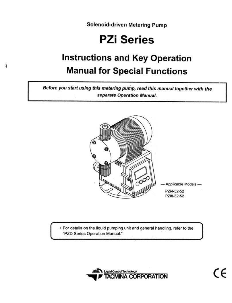
Tacmina PZi Series User manual

Tacmina

Tacmina PZi Series User manual

Tacmina PW Series User manual

Tacmina

Tacmina PW Series User manual

Tacmina PZD Series User manual

Tacmina

Tacmina PZD Series User manual

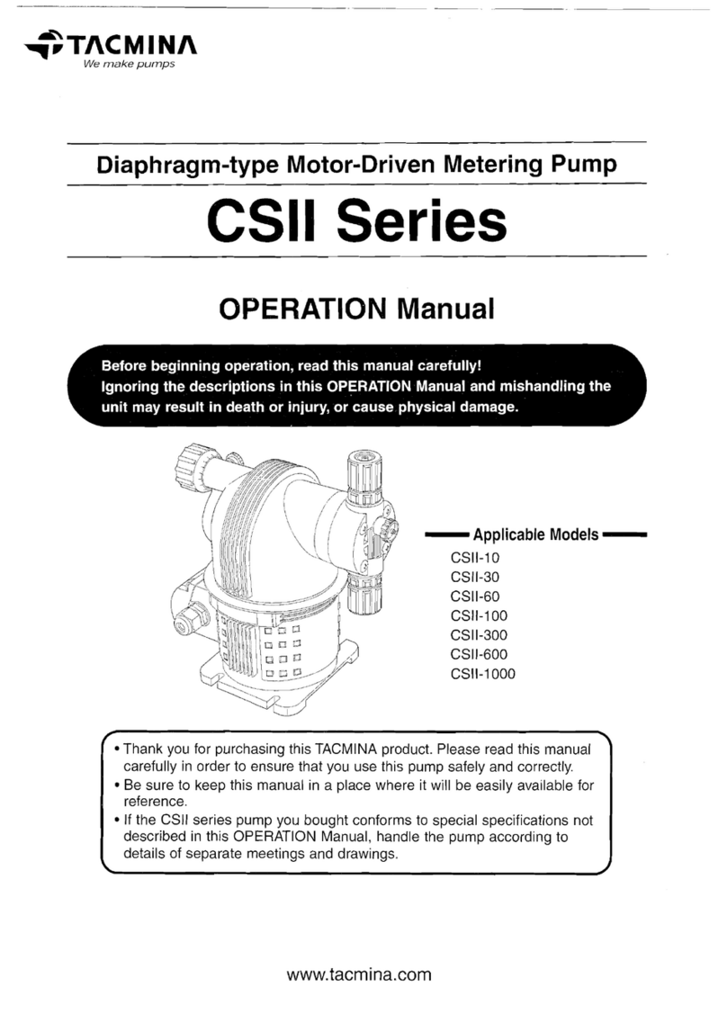
Tacmina CSII Series User manual

Tacmina

Tacmina CSII Series User manual

Popular Water Pump manuals by other brands

Pompetravaini BORA FP 243 operating manual

Pompetravaini

Pompetravaini BORA FP 243 operating manual

AR 3.8 DFL instruction manual

AR

AR 3.8 DFL instruction manual

VERDER HI-CLEAN VA-2H25 Repair parts list

VERDER

VERDER HI-CLEAN VA-2H25 Repair parts list

Astral Pool MAXI PLUS Programming instructions

Astral Pool

Astral Pool MAXI PLUS Programming instructions

Husqvarna WT 10MP Operator's manual

Husqvarna

Husqvarna WT 10MP Operator's manual

Zoeller 53 Series installation instructions

Zoeller

Zoeller 53 Series installation instructions

CLIVET WSAN-EE 82 Installation and use manual

CLIVET

CLIVET WSAN-EE 82 Installation and use manual

TOOLCRAFT TO-7159158 operating instructions

TOOLCRAFT

TOOLCRAFT TO-7159158 operating instructions

MasterCraft 062-3413-2 instruction manual

MasterCraft

MasterCraft 062-3413-2 instruction manual

Pentair Myers 4VL Installation and service manual

Pentair

Pentair Myers 4VL Installation and service manual

Meec tools 020715 operating instructions

Meec tools

Meec tools 020715 operating instructions

Masterflex QUATTROFLOW 1200S OPERATING AND INSTALLATION Manual

Masterflex

Masterflex QUATTROFLOW 1200S OPERATING AND INSTALLATION Manual

Gorilla Concrete Tools GP-2 product manual

Gorilla Concrete Tools

Gorilla Concrete Tools GP-2 product manual

Regulus CSE MIX W6 1F Installation and operation manual

Regulus

Regulus CSE MIX W6 1F Installation and operation manual

CRANE PUMPS & SYSTEMS OGP Series installation manual

CRANE PUMPS & SYSTEMS

CRANE PUMPS & SYSTEMS OGP Series installation manual

PAW RHT Series Installation and operation instructions

PAW

PAW RHT Series Installation and operation instructions

Danfoss APP 1.5-2.5 Instruction

Danfoss

Danfoss APP 1.5-2.5 Instruction

Pfeiffer Vacuum HILOBE 1004 operating instructions

Pfeiffer Vacuum

Pfeiffer Vacuum HILOBE 1004 operating instructions

manuals.online logo
manuals.online logoBrands
  • About & Mission
  • Contact us
  • Privacy Policy
  • Terms and Conditions

Copyright 2025 Manuals.Online. All Rights Reserved.