.Fine-adjustment of discharge volume is per-
formed by the stroke adjustment dial. (See 10.
Setup Examples.)
2. Purpose of use
.This mode is used for flowrate proportional injec-
tion, etc. The pump operates proportionally to the
number of input pulses from the outside.
.Used when there are a few number of pulses
from a flow meter or other instrument, and the
chemical injection amount is too small. (setting
in direction for increasing injection amount)
.Fine-adjustment of discharge volume is per-
formed by the stroke adjustment dial. (See 10.
Setup Examples.)
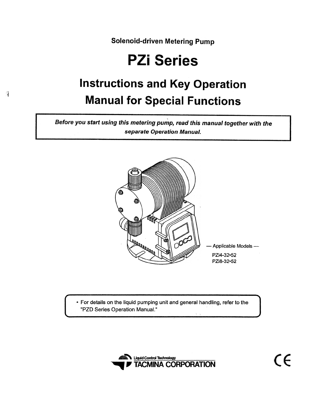
3.
LCD display
During a pump stoppageC
~~JTPI
DIY
During pump operation
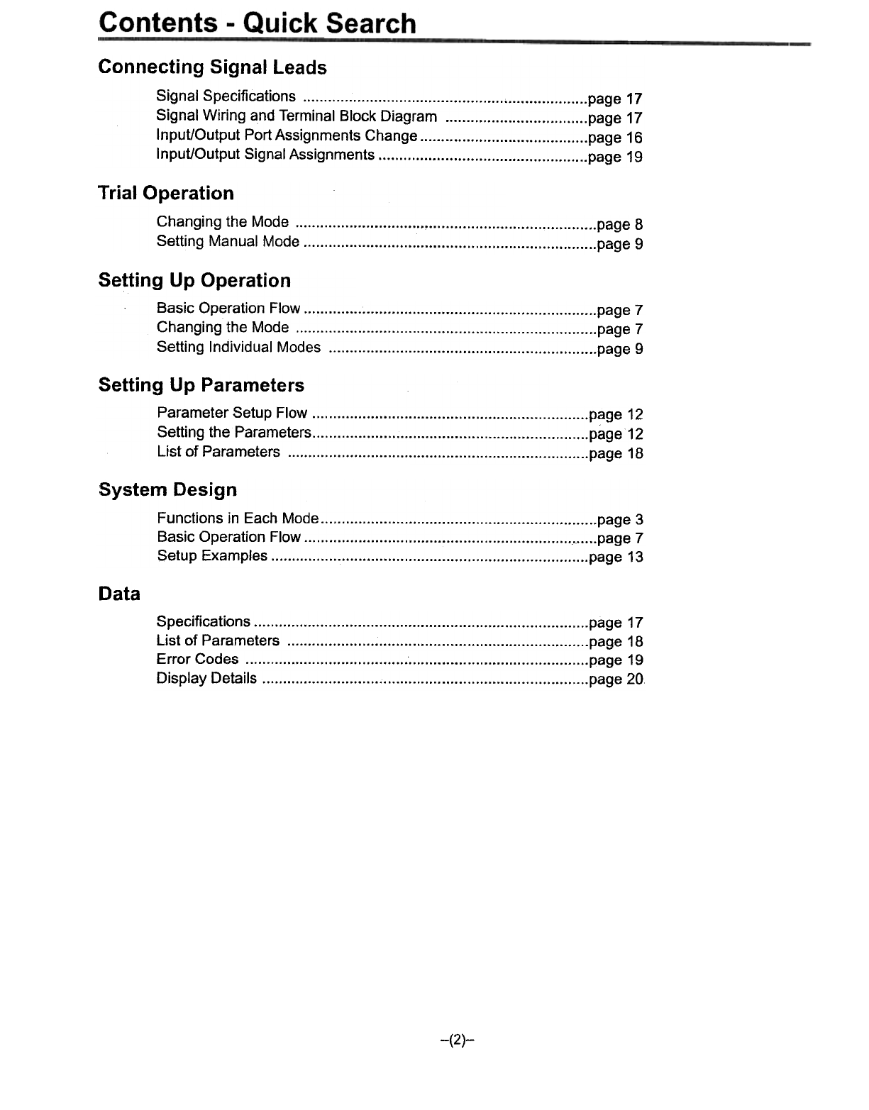
[=~~~~ 3. LCD display
During setting
-I I I , .-
ISTP-,'9999:-
DI' i II I \
During a pump stoppage
Fp II
I lOUt 'J
4. Operation control signal
No-voltage contact or open collector signal input
During pump operation
I -8 I
During setting
7-4 Multiplication mode
1. Basic operation
(1) Pulse signals from the outside are received, and
automatic operation is performed by the number
of strokes corresponding to the multiplication.
(2) The multiplication can be set within the range 1
to 9999. At this time, the pump operates at the
number of operation strokes (spm) set in the
manual mode.
Multiplication (can be set within range 1 to 9999)
As the default setting, external signals are canceled when an
external pulse input signal is input again during pump opera-
tion. External pulse input si~nals can also be held and stored
to memory by setting in this mode. (PZi8 type special func-
tion model only)
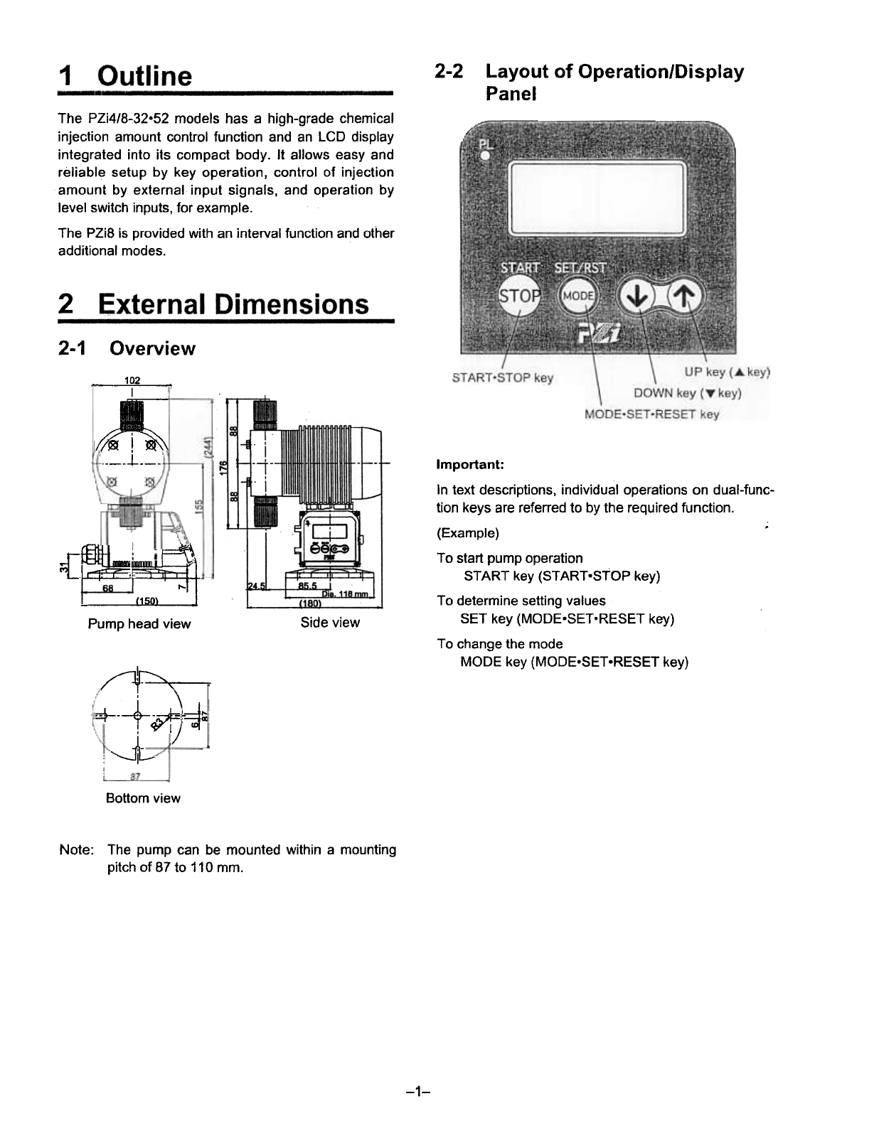
(A) Operates five times at 300 spm (fixed)
SignaI -] Jl jnnnnn ~no:sec. nnnnn
When set toJUUUULJUUUULJUUUUL
300 spm (A)
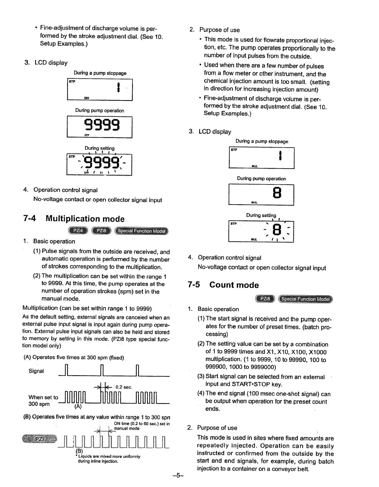
(8) Operates five times at any value within range 1 to 300 spn
ONlime (0.2 to 60 sec.) setin
manualmode
4. Operation control signal
No-voltage contact or open collector signal input
7-5 Count mode
1. Basic operation
(1) The start signal is received and the pump oper-
ates for the number of preset times. (batch pro-
cessing)
(2)The setting value can be set by a combination
of 1 to 9999 times and X1, X10, X100, X1000
multiplication. (1 to 9999, 10 to 99990,100 to
999900, 1000 to 9999000)
(3)Start signal can be selected from an external
input and START-STOP key.
(4)The end signal (100 msec one-shot signal) can
be output when operation for the preset count
ends.
2. Purpose of use
This mode is used in sites where fixed amounts are
repeatedly injected. Operation can be easily
instructed or confirmed from the outside by the
start and end signals, for example, during batch
injection to a container on a conveyor belt.
(B)
.Liquids are mixed more uniformly
during inline injection.
-5-