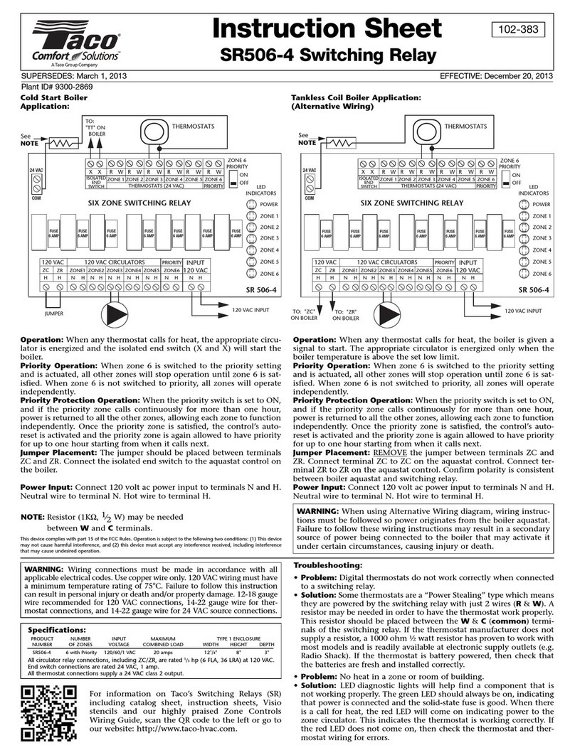
Operation: Wh n any th rmostat calls for h at, th appropriat circu-
lator is n rgiz d and th isolat d nd switch (X and X) will start th
boil r.
Priority Operation: Wh n zon 3 is switch d to th priority s tting
and is actuat d, all oth r zon s will stop op ration until zon 3 is sat-
isfi d. Wh n zon 3 is not switch d to priority, all zon s will op rat
ind p nd ntly.
Priority Protection Operation: Wh n th priority switch is s t to ON,
and if th priority zon calls continuously for mor than on hour,
pow r is r turn d to all th oth r zon s, allowing ach zon to function
ind p nd ntly. Onc th priority zon is satisfi d, th control’s auto-
r s t is activat d and th priority zon is again allow d to hav priority
for up to on hour starting from wh n it calls n xt.
Jumper Placement: Th jump r should b plac d b tw n t rminals
ZC and ZR. Conn ct th isolat d nd switch to th aquastat control on
th boil r.
Power Input: Conn ct 120 volt ac pow r input to t rminals N and H.
N utral wir to t rminal N. Hot wir to t rminal H.
Operation: Wh n any th rmostat calls for h at, th boil r is giv n a
signal to start. Th appropriat circulator is n rgiz d only wh n th
boil r t mp ratur is abov th s t low limit.
Priority Operation: Wh n zon 3 is switch d to th priority s tting
and is actuat d, all oth r zon s will stop op ration until zon 3 is sat-
isfi d. Wh n zon 3 is not switch d to priority, all zon s will op rat
ind p nd ntly.
Priority Protection Operation: Wh n th priority switch is s t to ON,
and if th priority zon calls continuously for mor than on hour,
pow r is r turn d to all th oth r zon s, allowing ach zon to function
ind p nd ntly. Onc th priority zon is satisfi d, th control’s auto-
r s t is activat d and th priority zon is again allow d to hav priority
for up to on hour starting from wh n it calls n xt.
Jumper Placement: REMOVE th jump r b tw n t rminals ZC and
ZR. Conn ct t rminal ZC to ZC on th aquastat control. Conn ct t r-
minal ZR to ZR on th aquastat control. Confirm polarity is consist nt
b tw n boil r aquastat and switching r lay.
Power Input: Conn ct 120 volt ac pow r input to t rminals N and H.
N utral wir to t rminal N. Hot wir to t rminal H.
Cold Start Boiler
Application:
Tan less Coil Boiler Application:
(Alternative Wiring)
Instruction Sheet
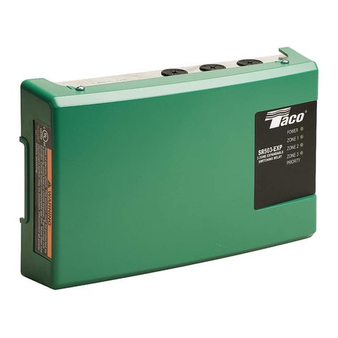
SR503-4 Switching Relay
102-379
SUPERSEDES: December 20, 2013 EFFECTIVE: January 18, 2017
Plant ID# 9300-2867
WARNING: Wh n using Alt rnativ Wiring diagram, wiring instruc-
tions must b follow d so pow r originat s from th boil r aquastat.
Failur to follow th s wiring instructions may r sult in a s condary
sourc of pow r b ing conn ct d to th boil r that may activat it
und r c rtain circumstanc s, causing injury or d ath.
Specifications:
P ODUCT NUMBE INPUT MAXIMUM TYPE 1 ENCLOSU E
NUMBE OF ZONES VOLTAGE COMBINED LOAD WIDTH HEIGHT DEPTH
S 503-4 3 with Priority 120/60/1 VAC 15 amps 121/4" 8" 3"
All circulator relay connections, including ZC/Z , are rated 1/3hp (6 FLA, 36 L A) at 120 VAC.
End switch connections are rated 24 VAC, 1 amp.
All thermostat connections supply a 24 VAC class 2 output.
WARNING: Wiring conn ctions must b mad in accordanc with all
applicabl l ctrical cod s. Us copp r wir only. 120 VAC wiring must hav
a minimum t mp ratur rating of 75°C. Failur to follow this instruction
can r sult in p rsonal injury or d ath and/or prop rty damag . 12-18 gaug
wir r comm nd d for 120 VAC conn ctions, 14-22 gaug wir for th rmo-
stat conn ctions, and 14-22 gaug wir for 24 VAC sourc conn ctions.
This device complies with part 15 of the FCC ules. Operation is subject to the following two conditions: (1) This
device may not cause harmful interference, and (2) this device must accept any interference received, including
interference that may cause undesired operation.
NOTE: R sistor (1KΩ, 1⁄2W) may b n d d
b tw n Wand Ct rminals.
Troubleshooting:
• Problem: Digital th rmostats do not work corr ctly wh n conn ct d
to a switching r lay.
• Solution: Som th rmostats ar a “Pow r St aling” typ which m ans
th y ar pow r d by th switching r lay with just 2 wir s (R& W). A
r sistor may b n d d in ord r to hav th th rmostat work prop rly.
This r sistor should b plac d b tw n th W& C(common) t rmi-
nals of th switching r lay. If th th rmostat manufactur r do s not
supply a r sistor, a 1000 ohm ½ watt r sistor has prov n to work with
most mod ls and is r adily availabl at l ctronic supply outl ts ( .g.
Radio Shack). If th th rmostat is batt ry pow r d, th n ch ck that
th batt ri s ar fr sh and install d corr ctly.
• Problem: No h at in a zon or room of building.
• Solution: LED diagnostic lights will h lp find a compon nt that is not work-
ing prop rly. Th gr n LED should always b on, indicating that pow r is con-
n ct d and th solid-stat fus is good. Wh n th r is a call for h at, th r d
LED will com on indicating pow r to th zon circulator. This indicat s th
th rmostat is working corr ctly. If th r d LED do s not com on, th n ch ck
th th rmostat and th rmostat wiring for rrors.
For information on Taco’s Switching R lays (SR)
including catalog sh t, instruction sh ts, Visio
st ncils and our highly prais d Zon Controls
Wiring Guid , scan th QR cod to th l ft or go to
our w bsit : http://www.taco-hvac.com.
