manuals.online logo
Brands
  1. Home
  2. •
  3. Brands
  4. •
  5. Taco
  6. •
  7. Relay
  8. •
  9. Taco SR504-EXP-4 User manual

Taco SR504-EXP-4 User manual

For information on Taco’s Switching Relays (SR)
including catalog sheet, instruction sheets, Visio
stencils and our highly praised Zone Controls
Wiring Guide, scan the QR code to the left or go
to our website: http://www.taco-hvac.com.
Priority Oper tion: When the priority dip switch is set to ON and the
priority zone is actuated, all other zones will stop operation until pri-
ority zone is satisfied. When not switched to priority, all zones will
operate independently.
Mode Oper tion: When the dip switch is set to NORMAL, the end
switch relay will be energized if any zone is in operation. When the switch
is set to RESET, the end switch relay will only be energized if the priority
zone is in operation, or through the operation of a plug-in reset control.
Prim ry Pump Oper tion: When the dip switch is set to OFF, the pri-
mary circulating pump output will energize when any zone calls for heat,
except the priority zone. When the dip switch is set to ON, the primary
circulating pump output will energize when any zone calls for heat.
Post Purge Oper tion: When the dip switch is set to ON, the priority
zone output will stay energized for 2 minutes after its thermostat or
aquastat is satisfied, but not operate the boiler.
Priority Protection Oper tion: When the dip switch is set to ON,
and if the priority zone calls continuously for more than one hour,
power is returned to all the other zones, allowing each zone to function
independently. Once the priority zone is satisfied, the control's auto-
reset is activated and the priority zone is again allowed to have priority
for up to one hour starting from when it calls next.
Pump Exercise Oper tion: When the dip switch is set to ON, the
solid state timer cycles all the circulating pumps that are attached to
the Expandable Switching Relay at the selected time interval. The time
interval can be set for the pumps to run for either 30 seconds every 2
weeks or for 4 minutes every 24 hours.
Low Limit (ZC) Oper tion: When the dip switch is set to ON and the
boiler drops below the set low limit (terminal ZC connected to boiler),
all zone circulating pumps will stop. When the boiler rises above the
set low limit, the zone circulating pumps are allowed to operate.
End Switches (Dry Cont cts): The main end switch closes when any
zone thermostat calls for heat and the mode switch is set to NORMAL.
The main end switch also closes when the mode switch is set to RESET
and a PC Series boiler reset power control is calling for heat. The priority
end switch closes only when the priority zone thermostat or aquastat is
calling for heat.
Exp nsion Connections: Set the expansion switch to MASTER on the
switching relay that has the designated priority zone or is utilizing the
PC Series plug-in option. Set all other daisy chained controls to SLAVE.
Using thermostat wire (18-22 gauge) connect between terminals A, B,
C on the master control to the corresponding A, B, C on the SLAVE
control(s). Controls may be daisy chained up to 20 zoning panels using
any combination of -EXP controls (120 zones if all are 6 zone panels).
Thermost t Input (24 v c):
R Hot side of transformer. Connect to Ron thermostat.
W Switched R signal from thermostat. Connect to W on thermostat.
C Common side of transformer. Connect to COM on
thermostat (optional).
NET Network terminals 1 & 2 are tied together for wiring convenience
when using communicating style thermostats (optional).
120 VAC Connections (N is Neutr l, H is Hot):
Power Input Connect 120 Volt AC power
Prim ry Primary Pump (optional)
Zone 1-3 Circulator Zones
Priority Zone 4 Priority Zone (if enabled) or Zone 4
N/C Zone 4 Normally closed terminals for the Priority Zone.
Will deactivate on a Priority Zone call.
Cold St rt Boiler
Applic tion:
T nkless Coil Boiler
Applic tion: (Altern tive Wiring)
Instruction Sheet
SR504-EXP-4 Switching Relay
102-389
SUPERSEDES: December 20, 2013 EFFECTIVE: January 18, 2017
Plant ID# 9300-2874
For Both Cold St rt Boiler Applic tion nd T nkless Coil Boiler Applic tion (Altern tive Wiring)
For Cold St rt Boiler Applic tion
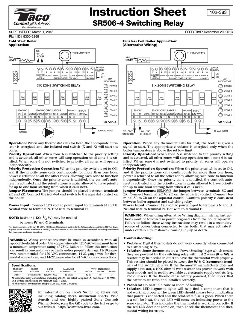
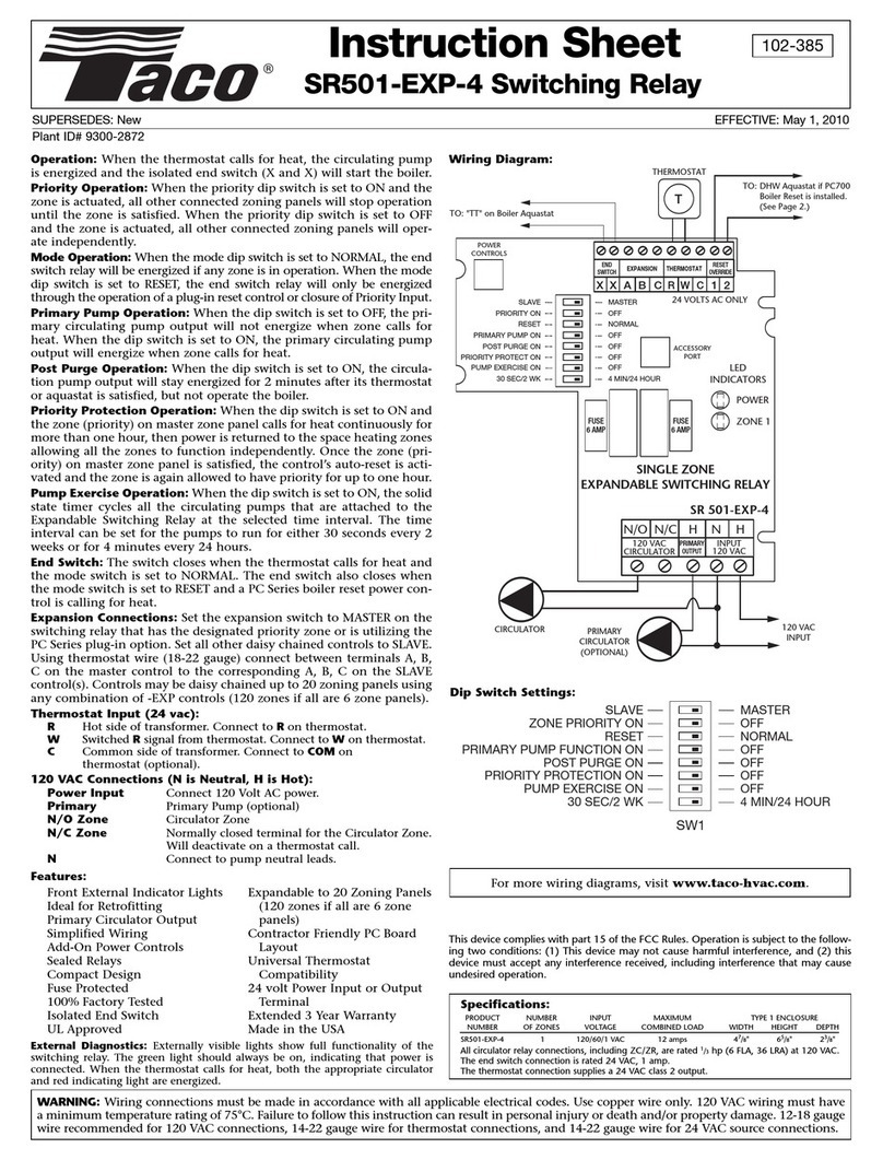
Oper tion: When any thermostat calls for heat, the appropriate circu-
lating pump is energized and the isolated end switch (X and X) will
start the boiler.
For T nkless Coil Boiler Applic tion (Altern tive Wiring)
Oper tion: When any thermostat calls for heat, the boiler will be enabled
and appropriate circulating pump is energized when the boiler tempera-
ture is above the set low limit and low limit (ZC) dip switch is set to on.
ZC nd ZR Termin ls: Connect terminal ZC to ZC terminal on the aqua-
stat control. Connect ZR to ZR terminal on the aquastat control. Confirm
polarity is consistent between boiler aquastat and switching relay.
WARNING: When using Alternative Wiring diagram, wiring instruc-
tions must be followed so power originates from the boiler aquastat.
Failure to follow these wiring instructions may result in a secondary
source of power being connected to the boiler that may activate it
under certain circumstances, causing injury or death.
Specific tions:
P ODUCT NUMBE INPUT MAXIMUM TYPE 1 ENCLOSU E
NUMBE OF ZONES VOLTAGE COMBINED LOAD WIDTH HEIGHT DEPTH
S 504-EXP-4 4 with Priority 120/60/1 VAC 20 amps 121/4" 8" 3"
All circulator relay connections, including ZC/Z , are rated 1/3hp (6 FLA, 36 L A) at 120 VAC.
End switch connections are rated 24 VAC, 1 amp.
All thermostat connections supply a 24 VAC class 2 output.
For more wiring diagrams, visit www.taco-hvac.com.
WARNING: Wiring connections must be made in accordance with all
applicable electrical codes. Use copper wire only. 120 VAC wiring must have
a minimum temperature rating of 75 C. Failure to follow this instruction
can result in personal injury or death and/or property damage. 12-18 gauge
wire recommended for 120 VAC connections, 14-22 gauge wire for thermo-
stat connections, and 14-22 gauge wire for 24 VAC source connections.
Taco, Inc. will repair or replace without charge (at
the company’s option) any product or part which
is proven defective under normal use within
three (3) years from the date of start-up or three
(3) years and six (6) months from date of ship-
ment (whichever occurs first).
In order to obtain service under this warranty, it is
the responsibility of the purchaser to promptly
notify the local Taco stocking distributor or Taco
in writing and promptly deliver the subject prod-
uct or part, delivery prepaid, to the stocking dis-
tributor. For assistance on warranty returns, the
purchaser may either contact the local Taco
stocking distributor or Taco. If the subject product
or part contains no defect as covered in this war-
ranty, the purchaser will be billed for parts and
labor charges in effect at time of factory exami-
nation and repair.
Any Taco product or part not installed or operat-
ed in conformity with Taco instructions or which
has been subject to misuse, misapplication, the
addition of petroleum-based fluids or certain
chemical additives to the systems, or other
abuse, will not be covered by this warranty.
If in doubt as to whether a particular substance is
suitable for use with a Taco product or part, or for
any application restrictions, consult the applica-
ble Taco instruction sheets or contact Taco at
[401-942-8000].
Taco reserves the right to provide replacement
products and parts which are substantially simi-
lar in design and functionally equivalent to the
defective product or part. Taco reserves the right
to make changes in details of design, construc-
tion, or arrangement of materials of its products
without notification.
TACO OFFERS THIS WARRANTY IN LIEU OF
ALL OTHER EXPRESS WARRANTIES. ANY
WARRANTY IMPLIED BY LAW INCLUDING
WARRANTIES OF MERCHANTABILITY OR
FITNESS IS IN EFFECT ONLY FOR THE
DURATION OF THE EXPRESS WARRANTY
SET FORTH IN THE FIRST PARAGRAPH
ABOVE.
THE ABOVE WARRANTIES ARE IN LIEU OF
ALL OTHER WARRANTIES, EXPRESS OR
STATUTORY, OR ANY OTHER WARRANTY
OBLIGATION ON THE PART OF TACO.
TACO WILL NOT BE LIABLE FOR ANY SPE-
CIAL, INCIDENTAL, INDIRECT OR CONSE-
UENTIAL DAMAGES RESULTING FROM THE
USE OF ITS PRODUCTS OR ANY INCIDENTAL
COSTS OF REMOVING OR REPLACING
DEFECTIVE PRODUCTS.
This warranty gives the purchaser specific rights,
and the purchaser may have other rights which
vary from state to state. Some states do not
allow limitations on how long an implied warranty
lasts or on the exclusion of incidental or conse-
quential damages, so these limitations or exclu-
sions may not apply to you.
LIMITED WARRANTY STATEMENT
2 Exp nd ble Switching Rel ys Connected Together
SLAVE
ZONE PRIORITY ON
RESET
PRIMARY PUMP FUNCTION ON
POST PURGE ON
PRIORITY PROTECTION ON
PUMP EXERCISE ON
30 SEC/2 WK
MASTER
OFF
NORMAL
OFF
OFF
OFF
OFF
4MIN/24 HOUR
LOW LIMIT (ZC) ON OFF
Dip Switch Settings:
This device complies with part 15 of the FCC ules. Operation is subject to the
following two conditions: (1) This device may not cause harmful interference,
and (2) this device must accept any interference received, including interfer-
ence that may cause undesired operation.
Troubleshooting:
• Problem: Digital thermostats do not work correctly when connected
to a switching relay.
• Solution: Some thermostats are a “Power Stealing” type which means
they are powered by the switching relay with just 2 wires (R& W). A
resistor may be needed in order to have the thermostat work properly.
This resistor should be placed between the W& C(common) termi-
nals of the switching relay. If the thermostat manufacturer does not
supply a resistor, a 1000 ohm ½ watt resistor has proven to work with
most models and is readily available at electronic supply outlets (e.g.
8the batteries are fresh and installed correctly.
• Problem: No heat in a zone or room of building.
• Solution: LED diagnostic lights will help find a component that is
not working properly. The green LED should always be on, indicating
that power is connected and the solid-state fuse is good. When there
is a call for heat, the red LED will come on indicating power to the
zone circulator. This indicates the thermostat is working correctly. If
the red LED does not come on, then check the thermostat and ther-
mostat wiring for errors.
NOTE: Resistor (1KΩ, 1⁄2W) may be needed
between Wand Cterminals.
Optional power stealing thermostat resistor part number: S T -001 P
(Value: 1000 Ohms, 1/2 watt or higher)
eplacement Switching elay fuses part number: S 6A-001 P
(Manufacture: Littlefuse, Part Number: 229006)
A Taco Family Company
2017

Other Taco Relay manuals

Taco SR502 User manual

Taco

Taco SR502 User manual

Taco SR502-4 User manual

Taco

Taco SR502-4 User manual

Taco SR503-EXP-4 User manual

Taco

Taco SR503-EXP-4 User manual

Taco SR501-EXP-4 User manual

Taco

Taco SR501-EXP-4 User manual

Taco SR506-EXP-4 User manual

Taco

Taco SR506-EXP-4 User manual

Taco Comfort Solutions SR506-4 User manual

Taco

Taco Comfort Solutions SR506-4 User manual

Taco SR501-4 User manual

Taco

Taco SR501-4 User manual

Taco SR501-HC-4 User manual

Taco

Taco SR501-HC-4 User manual

Taco FuelMizer SR501-OR-4 User manual

Taco

Taco FuelMizer SR501-OR-4 User manual

Taco SR501-EXP-4 User manual

Taco

Taco SR501-EXP-4 User manual

Taco FuelMizer SR501-OR-4 User manual

Taco

Taco FuelMizer SR501-OR-4 User manual

Popular Relay manuals by other brands

Pickering 4-781A Series user manual

Pickering

Pickering 4-781A Series user manual

Pilz PZE x4p operating manual

Pilz

Pilz PZE x4p operating manual

Aiphone RY-ES Installation & operation instructions

Aiphone

Aiphone RY-ES Installation & operation instructions

Siemens SIPROTEC 7SD610 manual

Siemens

Siemens SIPROTEC 7SD610 manual

Siemens 7SR210 Argus Application guide

Siemens

Siemens 7SR210 Argus Application guide

ZIEHL TR1200IP operating manual

ZIEHL

ZIEHL TR1200IP operating manual

Siemens Argus 7SR11 manual

Siemens

Siemens Argus 7SR11 manual

Owon CB432-DP quick start guide

Owon

Owon CB432-DP quick start guide

Plejd REL-01-2P installation manual

Plejd

Plejd REL-01-2P installation manual

LVS LUT-ALCR-D-FM installation instructions

LVS

LVS LUT-ALCR-D-FM installation instructions

Cooper Wheelock XRT-T-40 overview

Cooper Wheelock

Cooper Wheelock XRT-T-40 overview

National Instruments USB-9481 USER GUIDE AND SPECIFICATIONS

National Instruments

National Instruments USB-9481 USER GUIDE AND SPECIFICATIONS

Rockwell Automation Allen-Bradley 440R-GL2S2T user manual

Rockwell Automation

Rockwell Automation Allen-Bradley 440R-GL2S2T user manual

Pilz PNOZ e4.1p operating manual

Pilz

Pilz PNOZ e4.1p operating manual

ZIEHL SPI1021 operating manual

ZIEHL

ZIEHL SPI1021 operating manual

GE T35 instruction manual

GE

GE T35 instruction manual

Pilz PNOZ s2 operating instructions

Pilz

Pilz PNOZ s2 operating instructions

Alstom MCAG 14 Service manual

Alstom

Alstom MCAG 14 Service manual

manuals.online logo
manuals.online logoBrands
  • About & Mission
  • Contact us
  • Privacy Policy
  • Terms and Conditions

Copyright 2025 Manuals.Online. All Rights Reserved.