TFM VT-222 Vortex Flowmeter User Manual
H86CT1 Product Manual
Technical Support
TacticalFlowMeter VT-222 Vortex flowmeters utilize piezo sensors to detect the Vortex Shedding
Frequency. We integrate internal Pressure and Temperature sensors to provide for full multivariable
operation. Please read this manual carefully before using the meter. If you have any questions, please
do not hesitate to contact us.
Company:Take 5, Inc. dba TacticalFlowMeter.Com
Tel:831-244-8080 x1 Sales, x2 Support
Website:www.TacticalFlowMeter.com
Electronics Specifications
Power Supply: 12-32VDC
Operating Temperature: -20°C to 70°C(with LCD -40°C to 85°C(without LCD)
Output: 4-20mA output
Configuration: Flow mode, Flow unit, Range (Qmax), Density, Temperature, etc.
Alarm: Low alarm outputs 3.8 mA & high alarm can outputK-Factor linearity: The VT-222 provides 2 to 5
points of K-Factor linearity correction.
Local adjustments: Setting range and PV units, Density, Flow mode, damping, high alarm percent, low alarm
percent and data recovery etc.
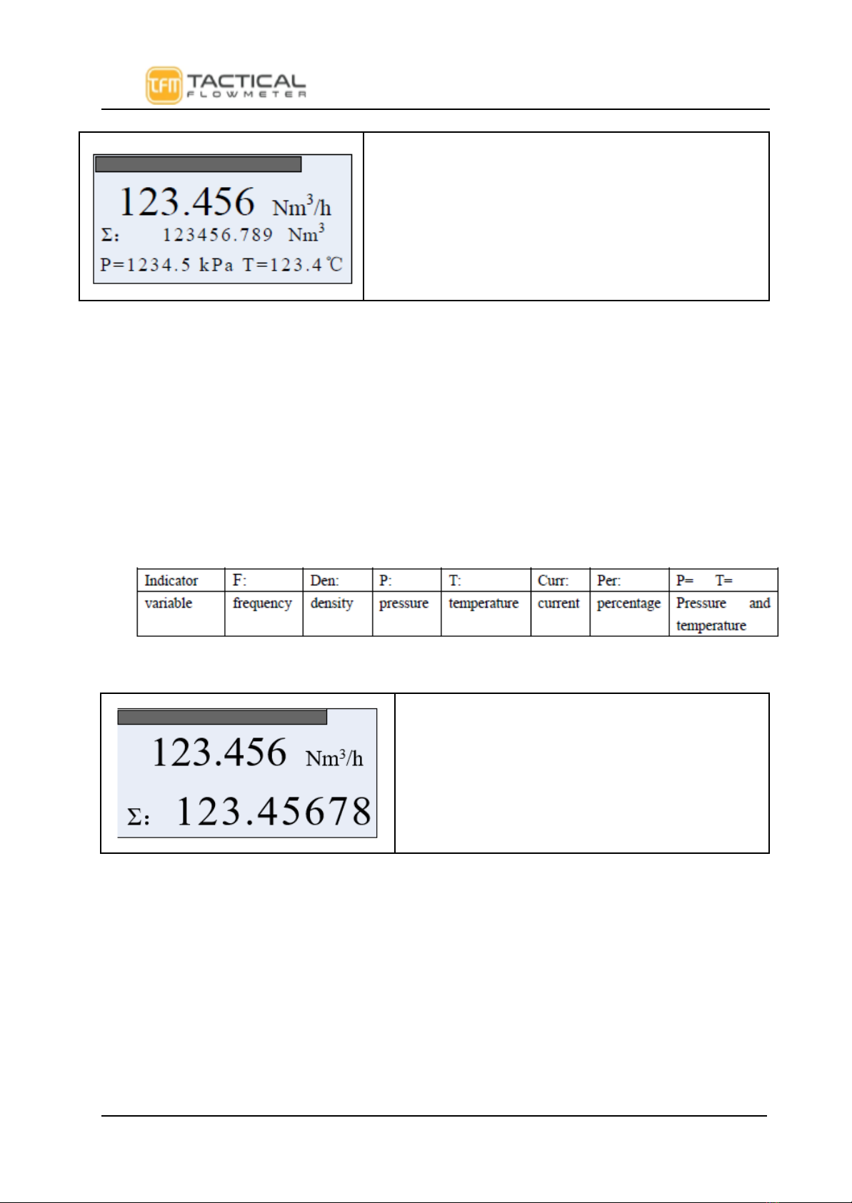
LCD display: Line 1 shows the instantaneous flow. Line 2 shows the totalized flow. Line 3 can display the
percentage, output current, temperature, pressure, density and more combinations easily selected by the user.
Multivariable Operation:The VT-222 supports real-time temperature and pressure compensation for gas, and
utilizes the international standard for the steam and density tables for temperature and pressure compensation as well
for superheated steam with pressure compensation or temperature compensation for saturated steam.
Temperature trim: High trim and low trim .
Pressure trim: High trim and low trim .
The VT-222 provides power-down protection and flow totalizer value storage functions.
Hardware
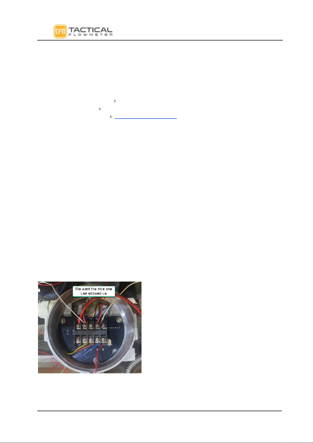
Terminal Board Wiring
The terminal board is used for connection to the external power supply, output pulse, the external
pressure sensor and temperature sensor.
The following are common wiring methods.
TFM VT-222 Vortex Flowmeter Quick Manual Rev 10f page 3 of 30