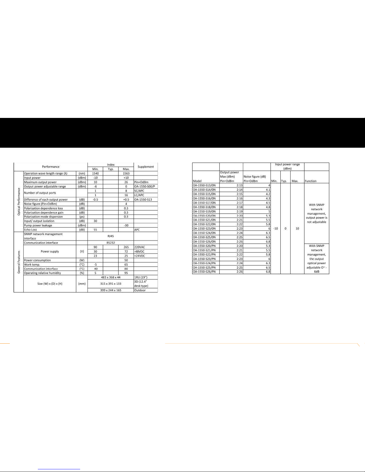
Taikan OA-1550-S00 series User manual

919 E. 29th St. Lawrence, KS 66046 // tel: 1-800-255-0247 // fax: 785-841-9512 // email: support@taikan.com // www.taikan.com
USER MANUAL
OA-1550-S00 Series

Taikan 1550nm Erbium Doped Fiber Amplifi er Owner’s Manual
This manual is intended for use by purchasers of Taikan’s OA-1550 family of optical amplifi ers and their qualifi ed
technicians. This document is the property of Taikan Corporation (Taikan) and embodies proprietary subject matter. All
design, manufacture, reproduction, use and sale rights regarding these products are expressly reserved. This manual may
not be reproduced without written consent from Taikan. All copyright, patent and trade secrets for this manual and product
are expressly reserved by Taikan. Specifi cations are also subject to change without notice.
Please read this manual thoroughly before use.
Retain this manual for future reference.

1.0 Product Summary 06
2.0 Amplifi er Controls 07
2.1 Powering On
2.2 Available Menus
2.3 Menu Defi nitions
3.0 Equipment Operation Principal 9
3.1 OA-1550 Amplifi er Circuit Principal
3.2 Carrier-to-noise Ratio
4.0 Description of Status Alarm 10
5.0 Operator Notice 10
6.0 Repair & Warranty Policies 10
7.0 Technical Specifi cations 11
TABLE OF
CONTENTS
Taikan // 919 E. 29th St. Lawrence, KS 66046 // tel: 1-800-255-0247 // fax: 785-841-9512 // email: support@taikan.com // www.taikan.com
OA-1550-S00 | 04

1.0 INTRODUCTION
PRODUCT SUMMARY
The OA-1550 series is a CATV booster optical amplifier with gain spectrum bandwidth of
1540-1565nm. This headend amplifier is designed for the application of single channel or
1-8 continuous ribbon channels (ITU wavelength). Generally, fi ber CATV systems operate in a
single wavelength without strict requirements on gain fl atness. THE OA-1550 booster amplifi ers
are designed with a low noise fi gure and high-saturated output power. It is applicable for central
headend, sub-headend, line relay, and other optical networks. The OA-1550 optical amplifier
utilizes a top-class pump laser and OFS erbium doped optical fi ber; perfect for APC, ACC and
ATC control.
The housing is designed for proper ventilation and heat-dissipation thereby ensuring a longer
product life and more reliable pump laser. On the rear panel a RS232 and RJ45 offer serial
communication and SNMP network management port. The LCD at the front panel displays
relevant parameters and warning LED lights. As a safety precaution the output laser will
automatically shut off if an optical input power is not detected. Lastly output ports can be installed
ON the front or rear panel depending on your desired preference.
Taikan // 919 E. 29th St. Lawrence, KS 66046 // tel: 1-800-255-0247 // fax: 785-841-9512 // email: support@taikan.com // www.taikan.com
OA-1550-S00 | 06
STANDARD FEATURES
• Erbium Doped Optical Fiber
• 1540~1563 nm Operating Wavelength
• Low Noise, High Output, High Reliability
• APC, ACC , ATC Controlled Selection
• 19” 1 U Standard Rackmount Housing
• Excellent P/P Ratio
• RS232 and RJ45 Connections
• Easy to Read LCD Screen

OVERVIEW:
This section of the manual gives an overview of the available menus in the OA-1550-S00 series amplifi er. All instructions in
Section 2.0 refer to the representation of the front panel shown in the image below. The user can scroll through the menus by
using the push buttons that are on the front panel located to the right of the LCD screen.
2.0 AMPLIFIER CONTROLS
Taikan // 919 E. 29th St. Lawrence, KS 66046 // tel: 1-800-255-0247 // fax: 785-841-9512 // email: support@taikan.com // www.taikan.com
OA-1550-S00 | 08
2.1 THE OPERATION OF THE PANEL:
2.1.1 INITIAL STEPS
A. Plug in 110V or 220V power supply
B. Turn on the power switch in the rear panel
C. Turn the laser key from OFF to ON. The laser status LED turns from green to red and the product enters
self-diagnostic mode.
D. After the self-diagnostic test, the amplifi er will enter working status and display “Descriptor”
2.1.3 MENU DEFINITIONS
1. Input power (INPUT):
Input power > +10 dBm, displays HIGHER
Input power <-10 dBm, displays LOWER
2. Output power (OUTPUT):
When input displays HIGHER or LOWER the output power displays NO OUTPUT.
3. Laser temperature °C (TEMP):
The laser temp is set at a range of 20°C~30°C. If the detected temp exceeds the range, the red light will show an alarm
and the power supply of the laser will be shut off automatically
4. Bias (BIAS):
Bias (BIAS): Bias is the key index of the laser. If the fi xed range is exceeded, the power supply of the laser will shut off
automatically to protect the laser
5. +5V voltage (+5V READS):
>±0.5V alarm
6. Press ▲\▼ key to update the IP address menu. Press ▲▼ at the same time to enter the menu, press ▼ to choose the
number that needs to be changed, push ▲ to update, and then press ▲▼ to enter into save and exit it.
For example, to update IP: 192.168.000.015; and you want to change 5 to 6, use ▲▼ to enter the IP menu, then press
▼ to choose the place of 5, press ▲ key to change 5 to 6, and then press ▲▼ to save the amended IP:192.168.000.016
7. LCD Contrast Level
Press ▲\▼ at the same time to enter menu edit status, press ▲▼ button to increase/decrease the contrast level, and at
last, press ▲\▼ button at the same time to save the modifi cation
2.1.2 START-UP MAIN MENU
Press the ▲\ ▼ buttons and the following menu will be displayed in sequence.
Menu #1 — Descriptor
Read-only menu, displays the amplifi er’s model number
Menu #2 — S/N
Read-only menu, displays the serial-number
Menu #3 — INPUT
Read-only menu, displays the input optical power
Menu #4 — OUTPUT
Read-only menu, displays the output optical power
Menu #5 — BIAS1
Read-only menu, displays the current of pump
Menu #6 — BIAS2
Read-only menu, displays the current of pump
Menu #7 — TEC1
Read-only menu, displays the current of pump in cooling/heating situation
Menu #8 — TEC2
Read-only menu, displays the current of pump in cooling/heating situation
Menu #9 — TEMP1
Read-only menu, displays the temperature of pump
Menu #10 — TEMP2
Read-only menu, displays the temperature of pump
Menu #11 — +5V READS
Read-only menu, displays the voltage +5V
Menu #12 — UNIT TEMP
Read-only menu, tells the chassis temperature
Menu #13 — IP
Adjustable list, displays the SNMP IP address
Menu #14 — Sub
Adjustable list, displays the net mask address
Menu #15 — GW
Adjustable list, displays the gateway SNMP address
Menu #16 — TR1
Adjustable list, displays the TRAP1 SNMP address
Menu #17 — TR2
Adjustable list, displays the TRAP2 SNMP address
Menu #18 — LCD Contrast Level
Adjustable list, displays the LCD contrast level

3.0 EQUIPMENT OPERATION
PRINCIPALS
Taikan // 919 E. 29th St. Lawrence, KS 66046 // tel: 1-800-255-0247 // fax: 785-841-9512 // email: support@taikan.com // www.taikan.com
OA-1550-S00 | 10
3.1 OA-1550-S00 SERIES AMPLIFIER CIRCUIT PRINCIPAL:
3.2 CARRIER-TO-NOISE RATION
4.0 DESCRIPTION OF STATUS ALARM
The working status indicator (LED) is near the power supply switch on the front panel. When it is green, the device is working
properly. When the indicator light is fl ashing red, there is an error.
1. Connect with 110V/or 220V power supply. After the amplifi er is plugged in, the display panel will show “READY; KEY
OFF” with a red indicator light.
2. Turn on with the key, the digital panel will display “KEY ON”. After a few seconds, the laser will turn on automatically and
the indicator light will turn from red to green.
3. Pressing both ▲▼ displays the product’s parameters.
4. If an error should occur, the red LED indicator light will fl ash and the laser will shut off automatically. Please refer to the
front display screen for the possible error.
5. As an added safety feature the laser’s power supply has time-delay function of 10 seconds.
5.0 OPERATION NOTICE
1. The amplifi er should have proper grounding with grounding resistance<4Ω.
2. The amplifi er is designed with a high reliability, steady voltage switch power supply. It has constant voltage overfl ow
protection and can work in 220 VAC electric network. The microprocessor monitors the output DC voltage.
3. To ensure the refl ection loss is ≥45dB, the amplifi er is installed with a SC/APC connector. Keep the connector clean
when installing. It is recommended that you frequently clean the connector with degreased cotton and anhydrous alcohol.
4. Do not turn on the amplifi er separately or without a protective cover at the connector end. Note: looking into the laser is
dangerous and can do permanent eye damage
6.0 GUARANTEE AND REPAIR
1. Each unit is packaged with a Product Qualifi cation Certifi cate and serial number. The amplifi er carries a limited
three-year warranty.
2. The pump laser is extremely delicate and only a certifi ed technician should be allowed to repair it. The micro-processor
software of the device has the function of monitoring laser status, digital display, trouble alarm, network management etc.
If the LED is fl ashing red (Alarm), please send the product back to manufacturer for repairing. The user should not open
the top cover for repair, even within guarantee period.
3. If the warranty seal on the product is broken or if the product has been tampered with a service fee may be charged.
4. Please refer to www.taikan.com for a detailed limited warranty policy.

7.0 TECHNICAL
SPECIFICATIONS
Taikan // 919 E. 29th St. Lawrence, KS 66046 // tel: 1-800-255-0247 // fax: 785-841-9512 // email: support@taikan.com // www.taikan.com
OA-1550-S00 | 10
7.0 GENERAL TECHNICAL SPECIFICATIONS 8.0 MODEL SPECIFICATIONS
*Please note: For the ON model SNMP network management output optical power is not adjustable. For the PN model
SNMP network management output optical power is adjustable from 0-6 dBm
Table of contents