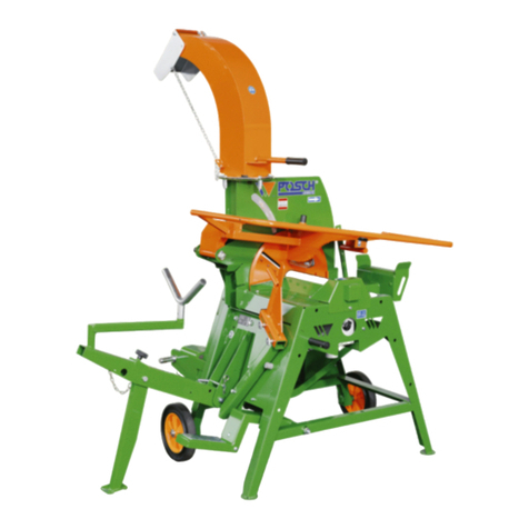
Tajfun RCA 400 joy User manual

1
Ver.: 2.5 07/2010-ENG
RCA 400 joy
Please read operating instructions carefully before installing and using the machine!
OPERATING INSTRUCTIONS
FIREWOOD PROCESSOR

2
TABLE OF CONTENTS
Chapter: Page:
1 GENERAL 3
1.1 MANUFACTURER’S ADDRESS 3
1.2 APPLICATION 4
1.3 SCOPE OF DELIVERY 4
1.4 OPTIONAL EQUIPMENT 4
1.5 TECHNICAL DATA 6
1.5.1 SPECIFICATION PLATE 6
2 SAFETY INSTRUCTIONS 7
3 MACHINE SETUP AND OPERATION 7
3.1 DISCHARGE CONVEYOR ASSEMBLY 8
3.1.1 RETRACTION OF DISCHARGE CONVEYOR 9
3.2 TRACTOR P.T.O. SHAFT DRIVE 9
3.3 CONNECTING THE LOG LOADER (OPTIONAL) 10
3.4 STARTING UP 10
3.5 TRANSPORT POSITION OF THE MACHINE 11
4 OPERATING THE FIREWOOD PROCESSOR 11
4.1 BASIC FUNCTIONS 11
4.2 NOISE 12
4.3 LOG FEEDING 12
4.4 SAWING 13
4.4.1 ADJUSTING THE WOOD LENGTH 13
4.5 SPLITTING 14
4.5.1 ADJUSTING THE HEIGHT OF THE SPLITTING WEDGE 14
4.5.3 MACHINE COVER WITH SAFETY SWITCH 16
4.6 DISCHARGE CONVEYOR 17
4.7 CLEANING DURING THE OPERATION 17
5 MAINTENANCE AND REPAIR 18
5.1 MAINTENANCE PLAN 18
5.2 TROUBLESHOOTING 19
5.3 CHAIN REPLACEMENT 21
5.4 CHAIN TENSIONING 22
5.5 CUTTING CHAIN SHARPENING ANGLES 22
5.6 SPLITTING WEDGE REPLACEMENT 22
5.7 HYDRAULIC SYSTEM OIL CHANGE 22
5.8 CHANGE OF FILTER INSERT 23
5.9 LUBRICATION OF THE ANGLE REDUCTION GEAR 23
5.10 CHAIN LUBRICATION 23
5.11 CUTTING CHAIN BELT REPLACEMENT 24
5.11.1 BELT TENSIONING 25
5.12 INDICATIONS OF IMPROPER USE 27
5.13 SUPPLIES 27
5.14 SPARE PARTS ORDERING 27
WARRANTY SHEET 32
5.11.2 CLEANING AND REPLACING THE AIR FILTER 26
4.5.2 PROPER USE OF SPLITTING WEDGE 15

3
Dear Customer,
By purchasing our firewood processor you obtained the equipment which will provide you with great help in
your work. To make operating the machine as safe and pleasant as possible, please carefully read this operat-
ing instructions and follow the safety and maintenance directives.
We would like to thank you for your trust and wish you great satisfaction in your work.
1 GENERAL
1.1 MANUFACTURER’S ADDRESS
Tajfun Planina, d.o.o., Planina 41a, 3225 Planina pri Sevnici, Slovenia
A In – feed Conveyor H Safety STOP Switch
B Machine Cover with Safety Switch I Low pressure Gauge
C Chainsaw cover J High pressure Gauge - Splitting
D Telescopic discharge Conveyor K Sawbar movement Gauge
E Control Handle
F Discharge Conveyor’s speed Regulator
G Log Loader Control Handle
A
B C
D
E F G H
K J I
1

4
1.2 APPLICATION
Firewood processor (RCA 400 joy) is a machine used for preparation of firewood. For open air use only! The
processor can handle logs from 10 to 40 cm (4" - 15,7") in diameter, which can be cut to 20 – 50 cm (7,9" -
20") length and thereafter split.
The work process is as follows:
1. Lifting and transportation of the log on the conveyor belt using the log loader (optional).
2. Transportation of the log with the conveyor belt to the limiter which sets the length of cut log. (Ch. 4.3).
3. Sawing with the chainsaw (Chapter 4.4).
4. Splitting (Chapter 4.5).
5. Transportation off the exit conveyor belt (Chapter 4.6).
1.3 SCOPE OF DELIVERY
RCA 400 joy
Discharge conveyor Operating instructions
Log Loader Control Valve –
integrated in the machine con-
trol panel
Chain 3/8" Oregon MULTI-
CUT ; Number of driving teeth
= 64, b=0.058” (1.5 mm)
Discharge Conveyor’s speed
regulator – integrated in Dis-
charge Conveyor
Manual Winch Operating In-
structions
Sawbar: Oregon 178SLHD009
or compatible
1.4 OPTIONAL EQUIPMENT
LOG LOADER DM 1511 - Tajfun (Figure 2)
LOG LOADER DM 2000 - Tajfun (Figure 2)
ELECTRIC POWER UNIT EP 11 with built-in 12V power supply - Tajfun
Chain lubrication oil is not included in the scope of delivery.
LOG LOADER DM 1511 - Tajfun
Retractable, with drive cylinders
Log loader length: 1840 mm
Lifting power: 4500 N
Weight: 160 kg
LOG LOADER DM 2000 - Tajfun
Retractable, with drive cylinders
Log loader length: 1650 mm
Lifting power: 7000 N
Weight: 330 kg
2
DM 1511 DM 2000

5
ELECTRIC POWER UNIT EP 11 - Tajfun
Motor Power: 11 kW
Weight: 197 kg
EP 12
LIVE LOG DECK RN 3000 - Tajfun
Dimensions: 5550 x 2010 x 1495 mm
Weight: 700 kg
Log Length: up to 6 m
Stock Capacity : 3t or up to 4 m3
RN 3000

6
1.5 TECHNICAL DATA
Length of Cut Log 20 – 50 cm (7,9"- 20")
Diameter of Log 10 – 40 cm (4 – 15.7")
Sawbar 17", b=0.058" (1.5 mm)
Chain 3/8", 64 pogonskih zob, b=0.058" (1.5 mm)
Splitting Power 150 kN (≈15T)
Machine Width 1290 mm (50.8″)
Machine Length (transport position) 2350 mm (92.5″)
Machine height (transport position) 2360 mm (92.9″)
Required Tractor Power 30 kW (40 KS)
Tractor P.T.O. Shaft Speed [400 – 430] min-1 (RPM)
Maximum splitting pressure 240 bar (3481 psi)
Oil Reservoir Volume 100 l (25 gal)
Chain Lubrication Oil Reservoir Volume 8 l (2 gal)
Operating Noise (Max.) 92 dB (A)
Weight 1080 kg (2381 lbs)
Discharge Conveyor
Conveyor Length 4000 mm (13’)
Conveyor Belt Width 430 mm (17.5″)
Maximum Speed 60 cm/s (24″)
Weight 130 kg (286 ls)
Required Tractor Outlet Voltage 12V
Minimal control fuses’ rating 16A
1.5.1 SPECIFICATION PLATE
Year of Manufacture
Serial number

7
2 SAFETY INSTRUCTIONS
The machine must be operated by one operator only. All other persons must stay away from the danger
zone (within the radius of 3 m ) Please ensure that there is nobody else in the near vicinity of the ma-
chine working area!
Machine operation and maintenance is allowed to qualified persons older than 18 years of age, only!
Before starting the work place the machine in a stable position, according to machine installation in-
structions!
Use only P.T.O. shafts of appropriate strength (min. 25 kW), with undamaged outer plastic protective
cover!
Never use damaged, cracked or deformed cutting chains, chain sprockets and sawbars!
All protective parts of the machine (safety nets, saw shield, covers ...) must be in place during the ma-
chine operation. Any modification of these protective parts is not permitted!
Always wear personal protective equipment (safety glasses, hearing protectors, gloves and forestry
boots)!
When troubleshooting, replacing the chain, cleaning or any other service procedure, always disengage
the P.T.O. shaft and shut down the tractor or unplug the power cord from the electrical outlet (EP 11)!
Do not wear loose clothes!
Keep the working environment clean and tidy!
Always use caution when operating the machine! Moving parts can cause serious injuries in case of
improper use of the machine!
Never leave the machine running without supervision!
Do not reach into the working area while the machine is in operation!
Before removing a wedged piece of wood, shut down the machine drive or turn off the machine.
When transporting the machine on public roads install lights on the read end of the machine!
For your own safety use only original spare parts and manufacturer approved accessories!
Damaged power cord or plug must be replaced immediately.
3 MACHINE SETUP AND OPERATION
Mount the firewood processor to the three-point tractor system using bolts. Lower tractor connecting han-
dles must be fixed with tensioning screws, so the machine can move transversely. When transporting the
machine, consider the weight of the whole machine (Chapter 1.5).
Connect the P.T.O. shaft to the cardan shaft and secure it using the safety chain.
Plug the machine control cable to the 12V outlet on the tractor.
Before the first installation also check the P.T.O. shaft length.
Check the P.T.O. shaft length by raising and lowering the machine to determine the position with the shortest
distance among connecting shafts. Tubes should be in this position, when the P.T.O. shaft is connected, app.
20 mm shorter.
In case the P.T.O. shaft is too long, it must be shortened:
Saw of steel and plastic tubes on both ends to the same length. Afterwards file down, clean and grease the
edges.
Do not use P.T.O. shaft with a clutch.
Tractor exit shaft and machine input shaft should be positioned as parallel as possible! P.T.O. shaft geometry
may otherwise cause uneven rotation transfer and subsequent vibrations. If this cannot be achieved you may
need to use P.T.O. shaft with wide angle linkages on both sides which is the only type of shaft that ensures
constant rotation with different angles (Figure: 3).
Model Dimensions Compatibility
PTO Shaft C Line-T 6BR + KK560 1 3/8’’ Z6 – 1 3/8’’ Z6; LKK = 560 EP 12 (RCA 380, RCA 400 JOY, RCA 480 JOY)
PTO Shaft C Line-T4 DZ BR + KK510 1 3/8’’ Z6 – 2X; LKK = 510 RCA 380, RCA 400 JOY, RCA 480 JOY
When using our machines, we recommend Tajfun PTO Shafts:
8
3.1 DISCHARGE CONVEYOR ASSEMBLY (in case of separate delivery)
Hydraulically driven discharge conveyor is also a component part of the firewood processor.
Place the discharge conveyor on the ground and move it closer to the connecting spot
Slide the discharge conveyor on the supporting forks and secure it with two screws (1– Figure:4)
Fasten the lifting package by fixing rope pulleys to their position (2-Figure: 5).
Use the hand winch (3-Figure:4) to lift the discharge conveyor slightly above the desired height and attach
the carrying chain (4-Figure:4).
Loosen the wire rope, so that the weight of discharge conveyor is distributed between the wire rope and
carrying chain (4-Figure:4)
Connect the hydraulic connectors::
- a - hydroengine return line - c - hydroengine discharge line
- b - hydroendine pressure line
3
4
3
4
ab
c
1

9
3.1.1 RETRACTION OF THE DISCHARGE CONVEYOR
Discharge conveyor is usually telescopically retracted in the machine transport position. By activating the ma-
chine, telescopic cylinder of the discharge conveyor automatically activates and fully extends the machine, so
the belt is tensioned.
3.2 TRACTOR P.T.O. SHAFT DRIVE
P.T.O. shaft (grooved shaft 13/8!" Z6 – DIN 9611A) must comply with the required driving power of the
machine (technical specifications).
The tractor P.T.O. shaft must rotate in a clockwise direction. In case you use EP11, the shaft must also ro-
tate in a clockwise direction.
Recommended rotating speed of the P.T.O. shaft: 420 min-1; max.: 430 min-1, min.: 400 min-1
When the machine is not coupled to its power source, place the PTO shaft into the rest hook.
To optimally tension the belt, move the control handle of the lifting table (G-Figure:1) to the lowering posi-
tion, which increases the system pressure. To position the Discharge Conveyor into the working – extended
position, the discharge conveyor valve (T-Figure:5) must be closed – fully tightened..
After you disconnect the machine drive, you can retract the discharge conveyor. Open the discharge conveyor
valve (T-Figure:5) and lift the machine cover (B-Figure:1) and leave the discharge conveyor to retract by its
own weight. Therefore put the machine in more upright position.
When the discharge conveyor is retracted, close the discharge conveyor valve (T-Figure:5). The valve should
remain closed during the operation.
Before starting the machine, make sure to loosen the conveyor belt, by moving the Discharge Conveyor from
vertical to horizontal position using the hand winch (3-Figure:4). Otherwise damages to the belt can occur
during the extension procedure!
Ensure the clearance “t” between the nut
and the hand winch handle axis.
5
T
2
t

10
3.4 STARTING UP
Before each machine startup, it is necessary to check the chain tension and readjust it if necessary!
A too loose chain can induce vibrations, which unfavorably affect the drive belt’s operation. Increased vibra-
tions can also cause damages to the drive belt.
Check the oil levels of the hydraulic system and cutting chain lubrication system, before starting the machine!
Examine the machine and equipment for faults and check the chain lubrication
Place the tractor manual throttle handle in lowest position
Lift the machine cover (B-Figure: 1) to activate the safety switch and disengage all major machine func-
tions
Engage the P.T.O. shaft drive and start the machine.
It may be necessary to turn on the headlights on some tractors to activate the 12V outlet
Set the required rotating speed of P.T.O. shaft (420 min-1) by manually adding the throttle
Lower the machine cover
Push the RESET button (green) on the control panel to start the operation
Check the function of the emergency STOP switch.
RCA 400 joy :
Remove all wood remains and other particles from the splitting chute, before starting the machine!
Before starting the machine, make sure to loosen the conveyor belt, by moving the Discharge Conveyor from
vertical to horizontal position using the hand winch (3-Figure:4). Otherwise damages to the belt can occur
during the extension procedure!
3.3 CONNECTING THE LOG LOADER (OPTIONAL)
Position the log loader in line with the machine,
as shown in the picture. The log loader can be
turned 180°, depending on the position of the
logs. Connect the hydraulic pipes for forks’ op-
eration to connectors a and pipes for cylinder
rotation to connectors b. You can reverse the
pipes on the connectors b to reverse the rotating
direction.
To retract the log loader in working position use
the fork lifting cylinder but first unscrew the nut
on the safety pin. Protect the extended log loader
using the safety supports.
In case you will not use the log loader install the
connecting pipe c. Otherwise the machine will
not operate properly!
a
b c
6
Before you start to work, check all functions and safety features of the machine as described herebelow.

11
4 OPERATING THE FIREWOOD PROCESSOR
The machine must be operated by a single person. Please ensure that there is nobody else in the near vicinity
of the machine working area!
3.5 TRANSPORT POSITION OF THE MACHINE
The maximum allowable speed of the tractor
when transporting the machine on the rut or off-
road is 10 km/h (12 mph) and 40 km/h (25 mph),
when the tractor is driven on the asphalt roads.
Warning!!
Driving at unsuitable
speeds for the road condi-
tions can cause damages
to the machine or the trac-
tor.
4.1 BASIC FUNCTIONS
- Control handle (joystick) has the following functions (Figure: 8):
Left-Right —> direction of the in-feed conveyor belt
Down —> sawing (2 phases, first fastening of the log and start-
ing the operation of the cutting chain, then moving the chain-
saw)
Up —> splitting (push the handle in the upward direction
briefly; do not hold it this position)
- Control handle buttons:
Yellow Buttons—> moving the splitting wedge up/down
Red Button —> returning the splitting cylinder from any posi-
tion
Green Button —>RESET function, opening of trapdoors manu-
ally. After each machine shut down (lifting of the cover, push-
ing the STOP switch) it is necessary to push the RESET button
to restore control functions.
7
Additional functions:
Figure 8a—> safety STOP switch
Figure 8b —> log loader - lifting, low-
ering
Figure 8c—>conveyor belt speed
regulator
8
8a 8c 8b

12
9
A
11
12
10
4.3 LOG FEEDING
The in-feed conveyor must be placed in a horizontal working position before operation:
Pull out the safety pin (10-Figure:9)
Remove the support limiter (12-Figure:9)
Lower the in-feed conveyor (A-Figure:9) in horizontal position and support it using the supporting leg
(11-Figure:9)
Set the supporting leg so that the upper rod on the conveyor belt in the middle of the feed conveyor is
slightly elevated above the table (already factory set).
Activate the feeding by pushing the control handle (Figure:9a) right. You can stop it at any time (when the log
reaches length limiter), by returning the handle to the neutral position. If you push the handle left, the con-
veyor belt will run in the opposite direction.
Warning! Stop the feeding after the log reaches the length limiter, otherwise you can damage the in-feed con-
veyor belt!
During in-feeding both trapdoors lift and stay in the position (Figure: 9b) until the end of the sawing phase or
until the operator pushes the green RESET button.
In the in-feeding phase the cut length limiter moves in the correct position.
4.2 NOISE
Machine operator is exposed to the following noise levels, during the machine operation (measured near the
machine operator's ear):
RCA 400 joy
Idling: 85 dB (A)
Operation: 92 dB (A)
Therefore it is mandatory to wear hearing protectors while operating the machine.
9b
9a

13
4.4 SAWING
The chainsaw operates only during the sawing cycle.
Sawing operation begins with the movement of the control handle (Figure: 10) in the backward direction and
includes 2 phases. In the first phase, log holder (Figure: 10a) fastens the log and cutting chain activation
clutch is engaged (Figure: 10b). In the second phase, the saw bar movement begins. During the cutting opera-
tion the operator must hold the handle in this position, otherwise the saw will return to the primary position.
Sawbar moving cylinder (Figure: 10c) has 2 adjustable switches. Switch 1 (cylinder retracted) prevents opera-
tion of the conveyor belt when the sawbar is in the outside position; and switch 2 opens movable trapdoors
and returns the sawbar to the primary position.
Sawbar pushing force is factory adjusted and may not be altered. Sawbar moving speed is also set to a fixed
value. Sawing speed varies according to the sharpness of the cutting chain and type and width of the wood.
Before sawing always check sharpness and tension of the chain and the level of the chain lubrication oil.
The wood should not move during sawing operation. Be especially careful when cutting the last piece – both
clamps should hold the wood still. Otherwise damages to the sawbar and cutting chain can occur!
Movable trapdoors ensure better entry of the cut pieces to the splitting chute and remain in horizontal position
during sawing. Trapdoors open when the sawbar reaches the lower position (switch 2). Trapdoors can also be
opened manually at any time, by using the green button on the control handle. This is especially useful when
cutting warped wood which leans on the trapdoors and pushes the sawbar laterally and subsequently interferes
with sawing.
4.4.1 ADJUSTING THE WOOD LENGTH
The length of the firewood is set by adjusting the
position of the length limiter (14-Figure:11) and fix-
ing it in the required position using the fixing pin
(13-Figure:11).
Regularly clean the filter on the chainsaw drive and replace it, if necessary. A clogged filter prevents the air
from entering the machine and decreases cooling efficiency of the clutch elements and belt and lowers life
span of these elements.
11
14 13
10 10a
10b
10c
1
2

14
4.5.1 ADJUSTING THE HEIGHT OF THE SPLITTING WEDGE
Splitting wedge can be gradually lifted or lowered depending on the
diameter of the logs - so you split logs in center using the yellow but-
tons on the control handle (Figure:10).
Splitting wedge can be simply adjusted when the splitting chute is
empty or at the point when the splitting cylinder starts to move.
Lifting mechanism of the splitting wedge also allows partial height
movements of the splitting wedge during the splitting phase. In case
the wood gets stuck under the splitting wedge it must be removed to
prevent damage to the lifting mechanism of the splitting wedge.
To replace the splitting wedge, lower the mechanism in the lowest
position, pull the splitting wedge out and replace it. Afterwards lift the mechanism a
little to fasten the splitting wedge in the operating position.
4.5 SPLITTING
Splitting is performed by a splitting cylinder which pushes the log towards the splitting wedge. The splitting
speed depends on the wood resistance and changes during splitting. Since the splitting speed is inversely pro-
portional with the splitting force, the splitting cylinder enables greater splitting force at a lower speed and a
smaller splitting force at a greater splitting speed. The splitting cylinder automatically selects the necessary
speed or splitting force, which results in greater energy efficiency.
The activation of splitting cylinders is performed by pushing the control handle forward. Do not hold the han-
dle in this position! Cylinder will automatically move forward and backward. The return of the cylinder is ac-
tivated by adjustable switch located under the machine cover.
Before each splitting, make sure the log is positioned properly in the
splitting chute!
You can return splitting cylinder at any time by pushing the red button on
the control handle, by lifting the safety cover or by pushing the safety STOP
switch.
The wood may fall into the splitting chute diagonally. In this case it is nec-
essary to open the cover and reposition the wood, before splitting. Problems
may be also caused by wood pieces which were sawed sideways (especially
the last piece) which can get lifted during splitting and damage the machine.

15
To ensure the durability of your splitting wedge, follow these instructions:
1. The splitting wedge is designed exclusively for wood splitting up to the max. diameter specified on your
RCA machine.
2. The log in the splitting chute must always be longitudinally directed towards the splitting wedge. This pre-
vents unnecessary overloads and downtime.
3. The log in the splitting chute must always be centred on the vertical blade of the splitting wedge. This pre-
vents overloading of the side blades of the splitting wedge.
Dmax
Dmax
4.5.2 PROPER USE OF SPLITTING WEDGE

16
4.5.3 MACHINE COVER WITH SAFETY SWITCH
In case of eventual problems during the splitting phase, or in case the log is wrongly positioned in the splitting
chute, the splitting process must be stopped immediately. In this case it may be also necessary to switch the
cylinder, so the splitting cylinder which pushes towards the splitting wedge, moves back.
Machine cover (B-Figure:12) is linked to the safety switch, which disengages all major machine functions
when the machine cover is lifted: in-feed and discharge conveyors stop, splitting cylinder stop and sawbar is
withdrawn into the saw shield. Lifting the machine cover therefore acts also as a main safety switch.
The log can be reached by hand only when the machine cover is opened and machine is stopped. Sawing and
splitting cannot continue until the machine cover is closed and safety switch disengaged. To restore all ma-
chine functions it is necessary to push the green RESET button (Figure: 8).
4. Ensure that the splitting chute and splitting wedge are never obstructed. Always remove any wedged pieces
of wood.
5. Adjust the height of the splitting wedge to be slightly less than the mechanism permits. This allows the
splitting wedge to still “breathe” during the splitting so as not to burden the mechanism and the lower bla-
des of the wedge.
Failure to observe the instructions may result in mechanical damage to the wedge and the machine that
is not subject to reclamation.
5° min

17
4.6 DISCHARGE CONVEYOR
Lifting and lowering of the discharge
conveyor is performed with the hand
winch (23-Figure:13). When the desired
position is reached, secure it with the
chain, so that the weight of discharge
conveyor is distributed between the wire
rope and the carrying chain.
(24 – Figure:13).
When using and maintaining the hand
winch, follow the enclosed manufac-
turer’s instructions.
The speed of the discharge conveyor can
be adjusted using the discharge con-
veyor's speed regulator
(F-Figure:13).
13
23
F
24
12 B
STOPSTOP
C
4.7 CLEANING DURING THE OPERATION
a
c
b
Sawdust and wood remains begin to pile in cer-
tain areas during the operation. It is necessary to
regularly clean this areas:
a - wood remains under the machine. Wood
remains can fill the areas behind the splitting
cylinder and prevent the cylinder from return-
ing to the primary position. This can cause in-
creased pressure when idling and overheating.
b - wood remains under the discharge con-
veyor drive cylinder can damage the conveyor
belt.
c - sawdust produced by the chainsaw must be
removed regularly, so the sawdust doesn’t fill
the drain channel.

18
5 MAINTENANCE AND REPAIR
Regular machine maintenance ensures reliable operation and long lifetime of the machine.
Any work on the electric equipment may only be performed by a qualified electrician.
WHAT? WHEN? HOW?
Lubrication (Figure:18)
Lubrication spot: a, b, c, At least after every 80 hours of operation Lithium grease
Lubrication spot: d At least after every 80 hours of operation Lubrication spray
18
a
b
c
d
5.1 MAINTENANCE PLAN
Turn off the machine and disconnected the P.T.I shaft while performing any service or maintenance work.
WHAT? WHEN? HOW?
Check the tension of the cutting chain Before each use 5.2.
Check the tension of the cutting chain
belt
Every 50 hours of operation 5.11.1
Tighten any loose bolts and nuts and
hydraulic connections
After first hour of operation
After every 100 hours of operation
Using appropriate tools
Check the oil level Before each use visually
Hydraulic system oil change After 5000 hours of operation or once
every two years.
5.5.
Replacing the oil filter insert When changing the oil, or in case the
gauge indicator is in the red zone
Replace the filter insert.
Multiplication gear oil change After the first 50 hours of operation
Later, after every 1000 hours of
operation
Drain the oil in the appropriate vessel
from the lowest plug and replace the
plug. Fill the oil through the upper plug.
Cleaning and replacing the air filter on
the saw drive
Cleaning the filter - daily
Replacing the filter - every 6 months
5.11.2
Regularly remove peaces of wood and sawdust from the splitting chute, under the conveyor belt, under the
splitting wedge lifting mechanism and under the machine control handle!

19
5.2 TROUBLESHOOTING
PROBLEM POSSIBLE CAUSES SOLUTION
The machine does not react to control
handle commands. Electrical cable is not connected. Connect the cable to the tractor outlet.
Electric cable connected, no voltage in the socket or
wrong polarity.
Switch the tractor lights on, check the fuses (in the mac-
hine el. box and on the tractor), check the polarity.
RESET button wasn’t pushed.
Before every startup or after opening the safety cover it is
necessary to push the green RESET button (4.1) to re-
store all machine functions.
Machine vibrates excessively
Improper tractor and machine postion is causing
vibrations of the P.T.O. shaft.
Reconnect the tractor and the machine according to the
instructions (Chapter 3).
Worn-out P.T.O. shaft. Check and replace P.T.O. shaft if necessary.
Machine is overheating. Not enough oil in the reservoir. Add suitable quality oil (5.5).
Worn-out oil. Check the oil quality and replace the oil, if necessary.
Clogged oil filter, the filter gauge is in the red zone
when the oil is warm.
Replace the oil filter insert.
Excessive P.T.O. shaft rotating speed is causing
increased oil flow, higher losses and heating of the
oil.
Check the P.T.O./shaft rotating speed; it should be 400 to
430 rpm.
Splitting cylinder cannot return in the primary posi-
tion as too much sawdust and wood particles have
accumulated behind the cylinder. This is also indi-
cated by higher pressure when idling.
Lift the splitting cylinder cover and clean the wood re-
mains. Afterwards clean the area under the machine
regularly (4.6).
Overheating and the loss of splitting force can be
caused by internal splitting cylinder leakage.
Servicing may be required due to possible loosening of
the piston in the cylinder.
No hydraulic component is operational
and the control indicators on the valves
do not light when you move the control
handle.
Interrupted connection between angle multiplication
gear and hydraulic pump.
Replace the sprocket which connects multiplication gear
and hydraulic pump (servicing).
The machine became loud. Excessive P.T.O. shaft rotating speed. Check the P.T.O./shaft rotating speed, which should be
400 to 430 rpm.
Not enough oil in the multiplication gear. Check the oil level and replace it, if necessary (5.7)
P.T.O. shaft with built-in clutch is causing the noise. We do not recommend using P.T.O. shafts with clutches.
Use the regular P.T.O. shaft or P.T.O. shaft with wide
angle linkages on both sides which ensure constant trans-
fer of rotating speed.
Improper tractor and machine positioning; vibrations
are also present.
Reconnect the tractor and the machine according to the
instructions (Chapter 3).
P.T.O. shaft is not lubricated. Lubricate the shaft according to P.T.O. shaft instructions.
Discharge conveyor is not operating. Before staring up you didn’t push the RESET button. Before every startup or after opening the safety cover, it
is necessary to push the green RESET button (4.1) to
restore all machine functions.
Conveyor belt speed regulator is set in the lowest
position.
Set higher speed using the regulator (Figure 8c).
Conveyor belt is not moving although driving roller
is spinning. Conveyor belt is not tensioned enough.
Discharge conveyor valve (T-Figure 5) must be turned
down totally to prevent oil from exiting the cylinder
which tensions the belt.
Piece of the wood is blocking the rotation. Remove the foreign piece and regularly clean the area
under the driving roller.
Feed conveyor belt is not operating or
is slipping and the gauge shows the
pressure (90-100bar / 1305-1450 psi)
Hydraulic pipes for driving the log loader cylinders
are connected improperly and the oil flow is inter-
rupted.
Check the pipe connectors and push the couplings (3.3)
deep enough.
Log loader is not connected and quick couplings
under the table are loose.
Connect both couplings with the connecting pipe (3.3).
The roller is slipping, the belt isn’t tensioned enough. Tension the belt.
Log is too heavy and getting stuck. Saw the log in shorter pieces.
The conveyor belt is pulling in one
direction. Applicable to both feed and
discharge conveyors.
Bad positioning of the driven rollers. Set the driven roller so the conveyor belt will run in the
middle.
Hydraulic cylinder is leaking. Damaged seal. Seal replacement (servicing).
Damaged piston rod. Cylinder replacement (servicing).

20
More demanding procedures must be performed by a qualified technical service, only.
Splitting cylinder starts to split but
returns to soon or returns when you
start another function.
Splitting valve doesn’t remain in open position due to
too low electric power.
Check tractor power output. If you power the control
mechanism using other power supply to convert 220V to
12V, check its power output. Electric current can rise to
15A. DC current from such power supply has to be as
“even” as possible, without oscillation. Only transformer
does not suffice and has to include large condenser. Do
not use the cable with small diameter wires or exces-
sively long cable, due to high voltage drops in DC cur-
rent.
Cylinder performs forward movement,
but doesn't return automatically. You
can return splitting cylinder using the
red button on the control handle.
Final position inductive switch didn’t send the signal
to return the splitting cylinder.
It is necessary to set the position of the switch so it may
detect the final position of the cylinder. The switch is
located under the machine cover near the splitting cylin-
der.
.
Splitting cylinder is losing power,
transfers from high to low speed may
take longer, machine cannot reach
maximum pressure. Machine some-
times works normally and sometimes
doesn’t.
Possible internal leakage on the splitting cylinder due
to a loosen piston.
Cylinder repair is necessary.
Increased pressure (over 50bar / 725
psi) on the splitting gauge (J-Figure: 1)
when idling. Faster heating of the hy-
draulic oil.
Splitting cylinder cannot return in the primary posi-
tion as too much sawdust and wood particles have
accumulated behind the cylinder. This is also indi-
cated by higher pressure when idling.
Lift the splitting cylinder cover and clean the wood re-
mains. Afterwards clean the area under the machine
regularly (4.6).
Cannot set the height of the splitting
wedge.
Splitting wedge probably came out from the lifting
mechanism.
Reinstall splitting wedge to the lifting mechanisim.
Torn driving belt Too low speed of P.T.O. shaft and dull and loose
chain.
Replace the belt, use proper settings when working.
Belt is not tensioned enough. Replace the belt.
The chainsaw was blocked during sawing since the
wood was not fastened enough.
Replace the belt.
Stuck drive bearing. Replacement of damaged bearings (servicing).
The sawbar does not move, log holder
and chainsaw operate.
The foreign piece got stuck in the restrictor between
hydraulic cylinder and hydraulic block and blocks the
oil inflow
Remove the foreign piece by unscrewing the coupling
which holds the saw gauge (K-Figure). In this area the
restrictor is located in a small block. The foreign piece is
probably located there.
Slower sawing The chain became dull. Install a sharpened chain. The sawbar pushing force is
always the same, cutting speed depends on chainsaw
quality and resistance of the wood.
Sawbar overheating Not enough lubrication causes increased friction and
subsequent overheating.
Use dedicated chainsaw lubrication oil, increase lubrica-
tion pump flow (5.8), check oil quantity in the lubrication
reservoir, ensure uninterrupted oil flow to the groove on
the sawbar.
Sawbar pulls in one direction, cuts
sideways, overheating is possible.
Bent sawbar, probably cause by movement of the
wood during sawing.
Replace the sawbar.
A few cutting teeth on the chain are damaged. Sharpen or replace the chain.
The chaisaw damaged the surface of the chainsaw
holder. Chainsaw created the edge on the surface of
the holder and the sawbar rests on this edge. The
sawbar is therefore placed sideways relative to the
sawing direction.
Grind off the edge.
Chainsaw clutch is slipping Worn clutch plates. Replace the clutch plates.
Leaking of the oil on the slide surfaces. Determine the source of the oil, clean the slide surfaces.
PROBLEM POSSIBLE CAUSES SOLUTION
Table of contents