BGU USP 13-6 User manual

USER’S MANUAL
Carefully read entire manual before operating
the log splitter!
Südharzer Maschinenbau GmbH
Helmestraße 94 ∙ 99734 Nordhausen/Harz
Zentrale: +49(0)3631/6297-0 ∙ -111
Internet: www.bgu-maschinen.de
e-mail: [email protected]
- Set-up
- Use
- Maintenance
- Accessories
UNIVERSAL LOG
SPLITTER MODELS
USP 13 - 6, USP 16 - 2, USP 22-2
We manufactu-
re in Germany

2
CONTENT
1. INTRODUCTION 4
1.1 About the manual 4
1.2 Delivery and transport claims 4
2. PRODUCT OVERVIEW 6
(model usp 13 HZE-6) 6
6
3. WARNING LABELS AND SAFETY DECALS 7
4. SAFETY 9
4.1 Mandatory application field 10
5. ABOUT THE MACHINE 11
6. OPERATING INSTRUCTIONS 12
6.1 Adjusting the ram stroke length 12
6.2 Two-speeds operating mode 13
6.3 Function of the safety bracket 13
6.4 Setting the machine ready to work 14
6.5 Operating temperature 14
6.6 Working with the intermediate table 15
6.7 Temperature 15
7. TransportATION 16
7.1 Attaching the splitter to the adjustable three-point linkage 17
8. START-UP 18
8.1 Electric power mode 18
8.2 Three-point hitch mode 18
8.3 Tractor drive (PTO) 19
8.4 Direct connection to tractor hydraulics 19
9. REPAIRS AND 20
MAINTENANCE 20
9.1 Ordinary maintenance 20
9.2 Recommended oil types: 20
10. DISMOUNTING/DISPOSING OF AN 22
OBSOLETE MACHINE 22
11. TECHNICAL DATA 23
11.1 Noise emessions 23
12. WIRING DIAGRAM 25
13. OTHER AREAS OF POSSIBLE DANGER 26
13.1 Mechanical dangers 26
13.2 Electrical dangers 26

3
14. attachments 26
14.1 Radio-controlled winch FSW 750 D (Optional Art. Nr. 96010) 26
14.2 Tow bar with steering wheel (Optional Art. Nr. 94757) 26
14.3 Hydraulic log lifter (Optional Art. Nr. 94721) 26
14.4 Intermediate table (Optional) 27
14.5 Snap-in 4-ways wedge (Optional rt. Nr. 94716) 27
14.6 Mechanical log lifter (Optional Art. Nr. 94711) 27
15. LEGAL WARRANTY 28
16. EXTENDED WARRANTY 28
17. Ersatzteilliste 29
18. EC-STATEMENT OF COMPLIANCE 30

4
1. INTRODUCTION
Dear customer,
thank you very much for your trust and preference in choosing our
equipment and joining the number of our best customers in the world.
We are confident that our equipment will be up to all your expectati-
ons and assure you a long lasting quality and performance.
Our range of hydraulic log splitters includes various different models
of different splitting force:
USP 13 H - 6 USP 16 HZ - 2
USP 13 HZ - 6 USP 16 HZE - 2
USP 13 HE - 6 USP 22 HZ - 2
USP 13 HZE - 6
1.1 About the manual
Please take time to read this manual and learn to how operate and
maintain the splitter safely. For your easier reading this manual is laid
out in several sections. The sections are progressively numbered and
listed on the “content” page. The information, pictures and technical
data in this document reflect current or planned product features,
functions, and characteristics as of the publication date. Because of
on-going product improvements and feature additions, information in
this document is subject to change without notice. If you are experi-
encing a problem or functional trouble on your machine, please read
the “trouble-shooting” section 9 to identify possible causes and re-
medies. If the problem or functional trouble is not listed in the trou-
bleshooting chart contained in this manual, ask your Authorized Ser-
vice Centre for service. When you order parts maintenance or repair
services, your Authorized Service Centre, your dealer or eventually
the manufacturer need your machine serial number and engine serial
number. These are the numbers that you have recorded on the pro-
duct identification label of the manufacturer on the machine.
1.2 Delivery and transport claims
Upon delivery of the machine please check for visual machine dama-
ges such as damaged packing or scratched buckled parts. If so, make
a remark on all copies of the delivery bill before signing for accep-
tance. Also have the truck driver sign all copies of the delivery bill.

5
Also have the truck driver sign al copies of the delivery bill.
Should your shipper or the truck driver refuse to accept your claim,
fully reject delivery and make sure to inform us (the manufacturer)
immediately. No claims shall be taken into account by the shipper or
by the insurance company, if a reservation note is not made on the
delivery bill.
All transport damages must be notified within latest 2 days from de-
livery. Therefore delivery must be collected and inspected within this
term. Later claims shall be disregarded. In case of assumed but not
visually clear transport damages, make sure to mark the following
sentence on the delivery bill: „Reserved delivery due to assumed
transportation damages.“
Insurance and shipping companies act with extreme caution in case of
transport damages and sometimes refuse to accept responsibility.
Please make sure to provide clear and exhaustive evidence (photos)
of the claimed damages.
Thank you in advance for your help and attention to this matter.

6
2. PRODUCT OVERVIEW
(MODEL USP 13 HZE-6)
Ram
Control lever, left hand side
Log fender
Splitting wedge
Lower hitch pin
Control rod
Control lever, right hand side
Upper hitch pin
Vertical beam
Wheel
Oil tank
Floor plate
Safety U-clamp
Piston rod

7
1. Machine safety label
„Before setting-up, servicing, maintaining and clea-
ning the machine, disengage power and stop the
engine. Lock the tool and secure it against acciden-
tal start.“
This safety label reminds users of a pinched hands danger.
2. Machine safety label
„Read, understand, and follow all instructions in
this manual and on the splitter before starting!“
Keep at safe distance from machine moving parts!
3. Operation safety label „ADJUSTING THE SPLIT-
TING SPEED“
This label shows how to operate the control levers
4. Operation safety label „max p 240 bar“
This label shows the max admissible operating pressure.
5. Operation safety label “Pinched hands danger!“
Keep your hands off all moving machine parts! Pinched hands hazard
in the wedge dangerous area.
6. Maintenance label „Lubricate every 10 h“
7. Machine safety label „Direction arrow“
The motor must be turning in the same direction as shown by this ar-
row.
8. Machine safety label „Mind this direction arrow“
The motor must turn in the same direction as shown by this arrow.
3. WARNING LABELS AND SAFETY DECALS
p max 240 bar

8
9. Warning label (only on PTO powered version)
max. 520 Rev./min.
This label shows the max admissible number of PTO shaft revolutions.
10. Production label „Product identification“
This label shows the company details of the manufacturer and the
main machine technical data.
11. Identification label
“BGU-maschinen” manufacturer’s logo
12. Personal safety label
„Wear suitable protective cloths and boots“
13. Personal safety label
“WARNING! Always wear safety gloves” Wearing safety gloves.
14. Safety-alert symbol
„Danger: beware in this area!“
15. Personal protection sign
Mind these instructions for safe operation!
16. Position safety bar
This label indicates the position of the safety strap:
Transport position / working position
max. 520 U/min

9
Strictly perform installation, set-up, maintenance, cleaning
and transportation with the motor switched off and the machi-
ne firmly secured against accidental operation. Immediately
disconnect power off the machine in case of any eventual fault
or trouble.
Users shall strictly comply with these operation, set-up, maintenance,
repair and trouble-shooting instructions in order to assure safe ope-
ration and no damages to the equipment. Moreover we recommend
to let the machine be run only and strictly by trained and skilled staff
who must be familiar with the applicable occupational safety and
health administration rules as well as applicable transportation rules.
Incorrect use of the saw can cause serious injury or death.
No person under school leaving age should operate a log splitting ma-
chine. Those who have reached school leaving age but are below the
age of 18 may operate a circular saw if supervised by a competent
person of 18 years or over. The machine shall be installed and kept in
a suitable location selected by the customer for safest operation.
Machine instability can result in injury or severe damages. To ensu-
re stability during operation make sure to choose a flat, dry floor free
from any tall grass, brush or other interferences. The working area
around the machine must be kept as clear as possible from surroun-
ding tripping obstacles and slippery foundation floors should be duly
treated (do not use saw dust or wood ash for this purpose).
Make sure that the equipment stands on a safe stable foundation.
● Due and proper illumination of the working site must be provided at all times.
● Ensure that a wide but confined area is available around the machine
and assure maximum working freedom
● A skilled licensed electrician must be asked for any repair of the electric system
● Operators must wear steel toe safety shoes and snug-fitting tear resistant
work cloths
● No additional customised protections or tools should be provided on board of
the machine, other than the ones designed and supplied by the manufacturer
● NEVER leave the machine unattended with the running motor
Compliance to the applicable occupational safety and health administration
rules as well as applicable transportation rules must be assured at all times.
Operator‘s hearing protection, safety glasses, safety shoes and
gloves, close fitting cloths and other adequate protection means are
strongly recommended. Make sure that all access ways are properly
maintained so that wood can be safely delivered, loaded and shipped.
4. SAFETY

10
4.1 Mandatory application field
The log splitter is strictly designed for one-man operation. Never al-
low more than one person approach and work on the machine at the
same time.
This splitter is conceived for splitting short and long logs for firewood
preparation only. BEWARE: no crossgrain splitting is permitted. Always
split grain-wise and never split one log on top of the other. Make sure
to load your logs firmly on the floor plate against the vertical beam.
Any other use or splitting method is considered by the manufacturer
as “misuse”. In case of misuse the manufacturer will not be liable for
any injuries or damages and the operator will be held entirely
responsible.
Please make sure to comply with these set-up, operation and mainte-
nance/repair instructions in order to avoid happening of any injury or
dangerous condition.

11
5. ABOUT THE MACHINE
The log splitter is equipped with two-hands safety control.
This professional upright log splitter has own inbuilt hydraulic system
with pump and and oil reservoire into the vertical beam. The machine
comes from the factory with a first oil fill. A special level gauge on one
side of the beam provides for convenient oil level checkup.
The manufacturer performs default setting of main control valve be-
fore shipment so that no more adjustment is required on site.
This splitter is available in different versions with different power drive
systems to match with any operating requirement and condition of the
customers.
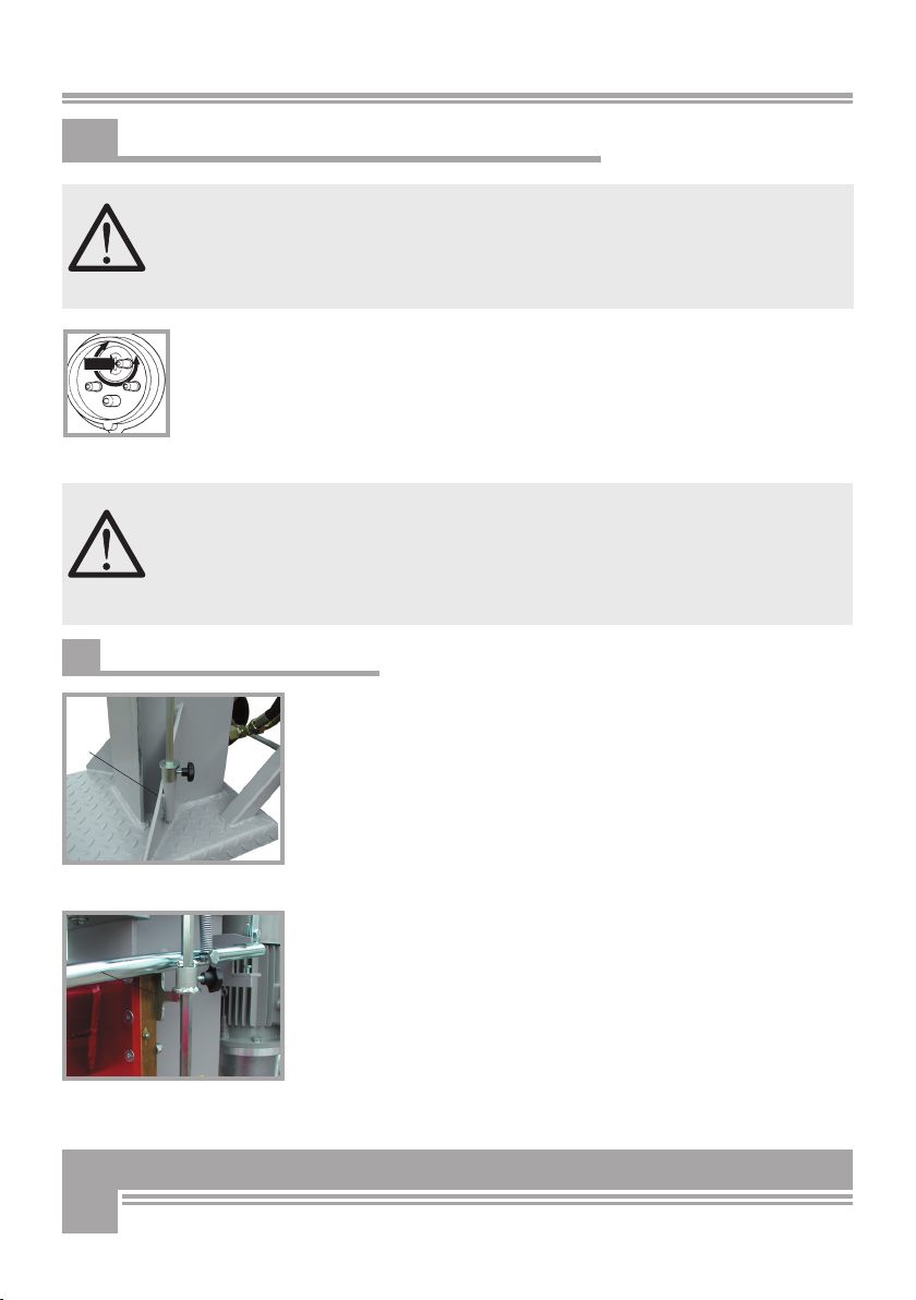
Make sure to secure the hydraulic ram to the beam, before you start-
up the splitter. The ram has an hydraulic cylinder with a flange that
must be secured on the respective upper plate of the beam using the
special fixation bolts. When doing this mind for the nuts (1) that must
be removed before bolting. (fig. 1)
To operate the machine, raise the ram all the way up and make sure
that the bolts keep showing through the flange. At this point hold the
wedge up and secure the assembly by tightening the special hex nuts.
When transporting the machine from one place to the other (or when
you are to store the machine inside) it may be convenient for you to
slide the ram all the way back down to fit into the splitter profile thus
saving a lot of space. When doing this make sure to first remove po-
wer from the splitter disconnecting all power sources (that is discon-
necting the driveshaft or the power cord).
Fig. 1
1
12
6. OPERATING INSTRUCTIONS
Fig. 3
Fig. 2
3
2
Locate your splitter only on firm, level ground. Site must be
free of slippery surfaces and tripping obstacles. The location
you choose should be flat, dry, and free from any interference.
Slippery foundation floors should be duly treated. For increa-
sed stability and safety, make sure to always load chunks on
their flat sawcut face.
Electrical specifications:
Before starting to work, quickly switch the 400V motor on and off to check that
rotation is performed in the direction shown by the arrow on the motor casing.
Should rotation be performed in the opposite direction, immediately stop the mo-
tor and use a phase inverter to switch the polarity in the plug of main power cord
using a phase changer. Operating the splitter while the motor turns in the wrong
direction may cause major, even permanent damages of the hydraulic pump!
Correct placement of the log on the pressure (floor) plate is a man-
datory condition for safe and efficient splitting. Be sure that the
body of the log is lying firmly against the vertical beam of the log
splitter and the end of the log is well supported by the pressure
plate. If the log tends to wobble, reposition it by turning it. Before
loading the next log on the machine and start a new cycle, clean
eventual residual chips and splinters away from the pressure plate.
6.1 Adjusting the ram stroke length
The ram travel is factory set to the maximum log capacity before
shipment. You just need to start the motor and the ram will slide au-
tomatically up to the maximum travel stroke.
In order to avoid dangerous hitting of the wedge against the pressure
plate on the floor, lift the lower stop-bush (2) up. (Fig. 2) The control
rod is duly scaled in order to facilitate a precise setting of the stroke.
BEWARE: the wedge will only travel down to the position set by the
stop-bush on the control rod.
For splitting full cord logs, slide the lower stop-bush (2) all the way
down so that the ram can slide over the entire stroke through the log.
If you move the upper stop-bush (3) down, the ram will no loger rai-
se all the way up and will stop as it reaches the position of the upper
stop-bush. (Fig. 3).
Use the upper handle located on the left-hand side of the beam to
secure the log central under the wedge. At the same time push the
handle on the righthand side down to activate the cylinder valve and
operate the splitter. In this situation, the splitter will stop and the
wedge will come to an immediate stop, if just one of the handles is
released.

13
6.2 Two-speeds operating mode
Press the control handle completely down to drive the ram down at its
fast-speed. If no throuhg-splitting is required, the ram must be ope-
rated at its slow speed (=more power). In order to do so, slightly re-
lease one of the two levers (preferably the right-hand one). When
doing so, the main control valve will switch over to max-power mode
instead of fast-speed mode. (Fig. 4).
Normal splitter operation will require the fast-speed mode. Just in ca-
se of a tough or very irregular log not being able to be split, you may
set the machine to slow-speed in order to gain power and perform th-
rouhgsplitting of the log.
If both handles (3 and 4) are released at once, the ram will slide au-
tomatically back to the initial position (Fig. 5), the control valve will
switch off and return to its neutral setting as soon as the ram reaches
its highest position.
Never place your hands on top of the log and never reach within the
splitting area on the machine, while the wedge is being operated.
Should any emergency arise and stopping be required, simply set the
control handles free from your grip. When doing this, the ram will
immediately travel all the way back up.
If a log is jammed on the wedge, it will hit against the safety U-clamp
as the wedge slides up. This will make the control valve switch to neu-
tral position preventing further operation and consequent possible da-
maging the splitter.
Logs that cannot be split through their entire length will jam to the
wedge and be lifted up, as the wedge slides up. BEWARE: check for
the clamping claw on the right-hand handle to avoid tearing.
On each side of the splitter vertical beam there are two log fenders
(6) specifically designed to avoid tipping over of the log sticks while
splitting is being completed (Fig.6).
Fig. 6
Fig. 5
Fig. 4
34
5
6
6.3 Function of the safety bracket
Called by the safety bar, (see Figure 1, point 2), it is possible that
one without a second person the splitter or vice versa brings the
transport position into the working position.
Before the operating levers are operated for splitting, must first of
Safety bar unlocked - being released (see Figure 7).
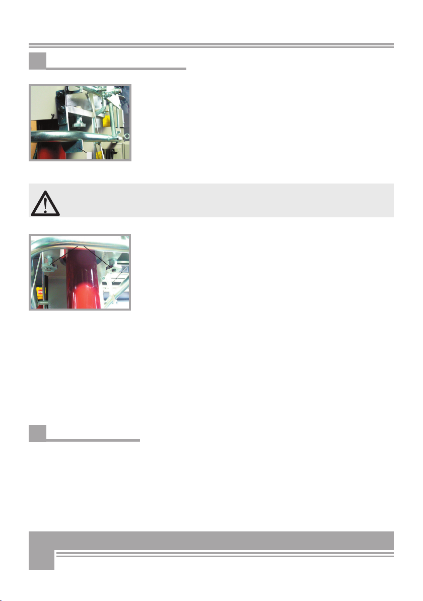
14
Abb. 7
Abb. 8
8
7
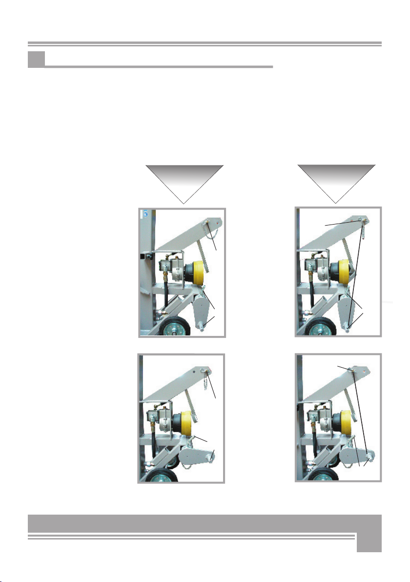
6.4 Setting the machine ready to work
To convert the machine from transport to splitting asset :
1. Engage the safety U-clamp →
Hook up the clamp to its catch
(Pos.7,
Fig. 7)
2. Remove (unscrew) both pommel grips (Pos. 8, Fig.8)
3. Perform power connection (electric or PTO)
4. Operate the left handle, pushing and holding it all the way down.
Press and hold the right handle down → to rive the ram all the way
up
Keep carefully rising the ram up all the way against the flange
of the upper cylinder casing. During operation of the safety bar
must be i m m e r hang out!
5.
Tighten both pommel grips (Fig. 8) again,
Release the U-clamp from its catch
→ the splitter wedge moves up:
→ the splitting position is now achieved.
To set the splitter ready for transportation after completing the work:
1. Secure the U-clamp (Fig. 7) →
hook up the clamp in its catch.
2. Operate both handles → let the wedge move down onto a wooden
block purposely located on the floor plate (approximately a 200 mm
thick block to use as safety seating during transportation) → release
both handles.
3. Remove (unscrew) the pommel grips (Fig. 8)
4. Push the left handle down
5. Release the U-clamp, cautiously settle the left handle back into start
position → let the ram move down and when it reaches its lowest posi-
tion push and maintain the handle
6. Secure the C-clamp → hook up
7. Disconnect power
8. Screw knob handles back
6.5 Operating temperature
At low ambient temperature the oil in the hydraulic circuit will thicken.
In this case, it is recommended to avoid sudden start-up (splitting wit-
hout warming the motor up) that could result into damages and trouble
of the hydraulic system. To assure trouble free operation of the hy-
draulic system at low ambient temperature, let the motor run idle and
cycle the unit several times till the oil in the hydraulic loop warms up.

15
6.6 Working with the intermediate table
With hinged intermediate table (accessory) the lower switching jack
ust solved and in the middle hole of the control rod be attached.
Then unhook the safety bar, now can be cleaved. After the operation,
the cylinder is moved upwards, the Abschaltbuchse the control rod
back into the lower hole of the Attached control rod and then removed
the table. The splitter can be brought back into the transport position.
6.7 Temperature
At low temperatures, the oil in the hydraulic system is still very vis-
cous. Instant work (columns) at such temperatures can cause damage
to the hydraulic system. The flawless To ensure operation of the hy-
draulic system, should the Only operated splitter at low temperatures
some idle time be to allow the hydraulic oil may heat up.

16
7. TRANSPORTATION
Abb. 9
Abb. 10
9
10
This machine is conceived for very ergonomic, easy handling thanks
to the special wheel arrangement in the rear bottom part of the ma-
chine. For long distance transportation, the machine can be conveni-
ently handled on the three-point linkage of your tractor.
To perform handling by rolling on its own wheels, first plug the pull-
rod (9) in the upper 3-point hitch and firmly secure it by means of the
pin. At this stage, find safe handling asset by leaning the splitter back
on the wheels till the wheels hit against the ground.
Alternatively lift the splitter using a crane or any equivalent lifting
equipment hooking the special lift bow (10) as shown on figure 10.
To perform transportation on the tractor, first lift the splitter
at least 20 cm above the ground while holding it straight up.
Disconnect power or remove the driveshaft and make sure that
the machine does not infringe the tractor profile nor blinds
tractor lights and signal lights (stop lights, tail lamps, etc...)
during transportation.
For road transportation compliance to the traffic rules of your
country is mandatory.
17
RIGHT PIN
POSITION WRONG PIN
POSITION
Fig. 12
Fig. 11
Fig. 14
Fig. 13
11
12
11
12
11
13
12
11
7.1 Attaching the splitter to the adjustable three-point linkage
Before transporting the splitter on the three-point hitch of your tractor,
check for the correct position of the upper (11) and lower hitch pin (12)
that must be lined up to each other. Accurate fitting of the pins in the
respective holes and precise line-up of their position (Figure 11 and 12)
is mandatory to assure trouble-free hitching. Wrong pins installation
and misalignement (see figure 13 and 14) may cause dangerous strain
of the machine which will void the warranty and release the manufac-
turer from any liability.
18
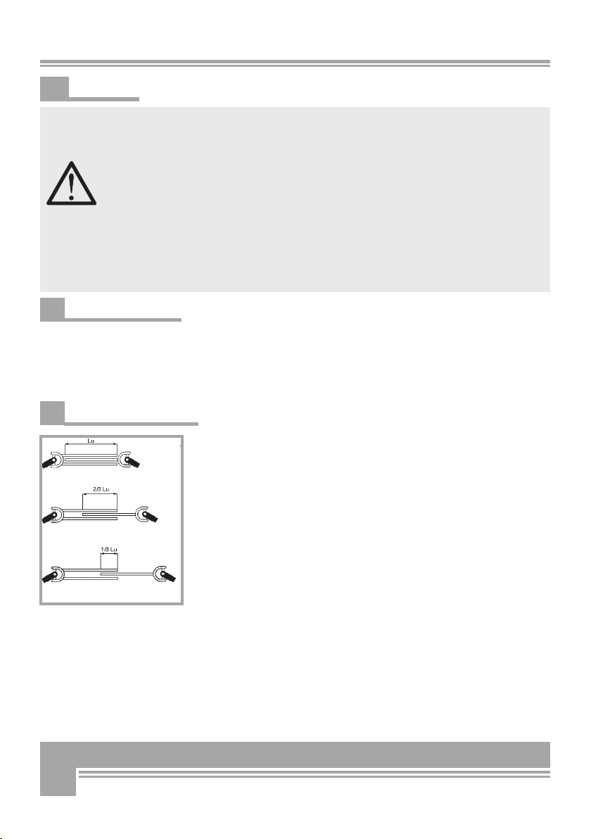
Fig. 15
Lu = pay length
closed length = longest telescopic half, fully
overlapping the shortest one
operating length = joint overlap by approx.
2/3 Lu
Longest (fully extended) length = joint overlap
by at least 1/3 Lu
8. START-UP
Before first use, make sure that the log splitter is in good conditions
and that there are no visual damages. Should any trouble or unusu-
al behaviour be detected, do not start splitting wood until these ha-
ve been fixed. First stop the machine, remove the cause of the trou-
ble and if required let skilled personnel perform a chekup before
you start working again.
For transportation purposes the ram is retracted within the splitter
profile alongside of the vertical beam. Before operating the splitter,
raise the ram up (Chapter 5 - About the splitter) in the initial opera-
ting position.
Periodically check the oil level inside the hydraulic oil tank and fill-
up if necessary. The splitter can be PTO powered by means of a dri-
veline or powered by tractor hydraulics by the hydraulic pump of
your tractor or by own electric motor depending on the version.
8.1 Electric power mode
Before attempting to operate the log splitter, make sure to duly con-
nect it to a power supply network of conformant safety specifications .
Do not switch the motor off till the splitting wedge reaches its upper
start-position.
8.2 Three-point hitch mode
PTO splitter versions must be connected by means of a driveshaft to
the power take off of your tractor. Connection of the driveshaft should
have no bigger play than 10 cm.
The PTO-driven version is equipped with a three-point linkage
to fit on the one available on your tractor. The drive shaft is going to
act as linkage and driving element between the tractor and the splitter
and should be therefore duly mounted and secured by the special pins
available on the machine.
For increased safety make sure that a minimum wrapping of 1/3 of the
total useful length is achieved (see figure 15 on the side).
Do not perform any repair, adjustment, cleaning or maintenance work
whatsoever while the machine is running (disconnect PTO-drive or switch the tractor off)!
Never use a PTO driveline without safety shield or with a damaged
guard and make sure that the shield is of the correct size and length for the drive
shaft. Driveshaft must be of an approved type and installed in compliance with
the instructions of the manufacturer.
PTO-versions are ground-driven, 3-point hitch implements. Lower the
machine to the “field” position when you are ready to use it.
During operation of a PTO powered splitter version, make sure that the splitter is
firmly secured to the three-point hitch of your tractor throughout the entire cycle!

19
8.3 Tractor drive (PTO)
Before uncoupling the processor, make sure to stop the tractor engine
in order to avoid damaging the tractor power drive.c
8.4 Direct connection to tractor hydraulics
Connect pressure to the coupling hose with a red mark and return
flow to the coupling hose with a green mark.

20
9. REPAIRS AND
MAINTENANCE
Make sure that the machine is fully disconnected and all
moving parts are secured before performing any main-
tenance/repair work on the machine. In the event of
any malfunctioning, switch the machine off before trou-
ble-shooting.
9.1 Ordinary maintenance
Make maintenance a regular part of daily operation. The daily mainte-
nance routine needs to include:
• Cleaning of the machine and clearing of all parts from residual wood
debris, chips, dust, bark pieces and eventual other waste.
• Greasing of the sliding pads inside the splitter stand.
• Hydraulic oil check and (in case of leakage) hydraulic hose and fit-
tings check-up to detect eventual oil leaks.
• Lubrication of all moving parts.
Oil or grease the wedge slinding pads after every 10 operation
hours.
9.2 Recommended oil types:
Periodically check the oil level inside the hydraulic oil tank. When doing
so, accurately avoid contaminating the tank with dirt, wood chips, sow
dust etc...Make sure that the splitter never runs without oil or with a low
oil level. When this happens, air is likely to reach inside the hydraulic
loop. Failure to maintain due oil level may cause poor running and irre-
gular splitter operation (very rough, back/forth or up/down motions) as
well as major pump damages. Please schedule your first oil change after
approximately 25-30 operation hours and later ones at least once a year.
Make sure to accurately clean the suction filter at each oil change.
Recommended oil types:
DEA HD B 46, Shell Tellus 10-46, Esso Nuto H 46.
After each new oil fill, operate the splitter and let it run for 2 or 3 complete
cycles before plugging the tank. This operation will help bleeding all residual
air out of the hysdraulic line. No parts or components of this rugged splitter
construction are likely to get damaged during compliant use and handling.
However always check all hydraulic hoses, fittings and couplings to detect
and repair eventual oil leaks. Do not check for leaks with your hand.
This manual suits for next models
2
Table of contents
Other BGU Log Splitter manuals


