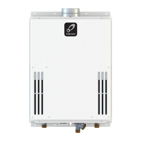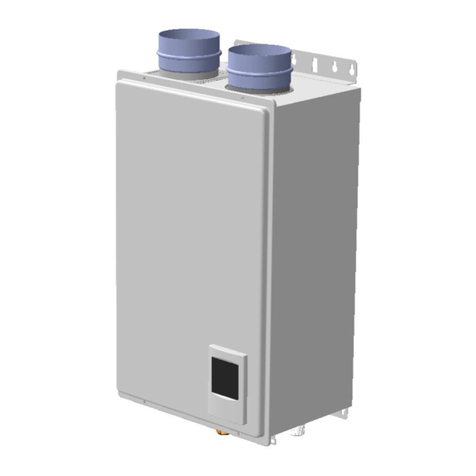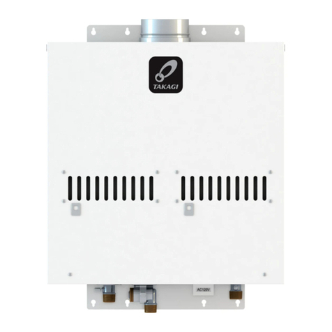
Iftheerrorcodeisindicatedonthe3‐digit7‐SegLEDonthePCB(Part#701)ofthewaterheater
(and/ortheremotecontroller),refertoSectionB.
<<Ittakeslongtimetogethotwateratthefixtures>>
・ Thetimeittakestodeliverhotwaterfromthewaterheatertoyourfixturesdependson
thelengthofpipingbetweenthetwo.Thelongerthedistanceorthebiggerthepipes,
thelongeritwilltaketogethotwater.
・ Ifyouwouldliketoreceivehotwatertoyourfixturesquicker,youmaywanttoconsidera
hotwaterrecirculationsystem.
<<Thewaterisnothotenoughorturnscoldandstayscold>>
・ Comparetheflowandtemperature.Refertothe“Outputtemperaturechart”ofthe
installationmanual.
・ Checkcrossplumbingbetweencoldwaterlinesandhotwaterlines.
・ Checkifthegassupplyvalvefullyopen,thegaslinesizedproperlyandthegassupplies
pressureenough.Refertothe“Gassupplyandgaspipesizing”oftheinstallationmanual.
・ Checkthesettemperature,andchangethedipswitchsetting.RefertoSectionD.
・ Referto“Watercircuit”inthissection.
<<Thewateristoohot>>
・ Checkthesettemperature,lowersettingtemperature.
<<Thehotwaterisnotavailablewhenafixtureisopened>>
・ Refertothe“Powersupplycircuit”and“Watercircuit”inthissection.
<<Fluctuationinhotwatertemperature>>
・ Checkifthefilteronthecoldwaterinletcleaned.(Part#409)
・ Checkifthegaslinesizedproperlyandthesupplygaspressuresufficient.
・ Checkforcrossconnectionbetweencoldwaterlinesandhotwaterlines.
・ Referto“Watercircuit”inthissection.
<<Unitdoesnotignitewhenwatergoesthroughthewaterheater>>
・ Refertothe“Powersupplycircuit”and“Watercircuit”inthissection.
・
Ifyouusetheremotecontroller,turnthepowerbuttononandthenthegreenLEDwilllit.
・ Checkifthefilteronthecoldwaterinletcleaned.(Part#409)
B.Errorcodes
031:Incorrectdipswitchsetting
・ CheckthedipswitchsettingsonthePCB.RefertoSectionD.
101:Warningforthe“991”errorcode
・
Checkthegastypeofthewaterheater.Ifit’swronggastypemodel,replacethewaterheatertocorrectone.
・ Checkifthereisanyblockage(Forexample,Dampersticking,VentFlapsinstalledonthe
terminator,Snowbuilduparoundterminator,Installedinacloset(Noventilationorlack
ofcombustionair))intheintakeairand/orexhaust.Refertothe“Venttermination
clearances”oftheinstallationmanual.
・ Ifthewaterheaterisinstalledasadirect‐ventsystem,checkwhetherthereareenough
distancebetweentheintakeairterminalandtheexhaustterminal.Refertothe“Vent
terminationclearances”oftheinstallationmanual.
・ Checkifthetotalventlengthdoesn’texceed50ftandthe#ofelbowsislessthan5Ea.
・ Checkthealtitude/elevationofareaofwherethewaterheaterinstalled.Refertothe
“High‐altitudefunction”oftheSectionD.Andchangethedipswitchsettings.
・ Checkifthereisgreaseand/ordirtintheburner(Part#101),andthefanmotor(Part
#114),especiallyifthewaterheaterhasbeeninstalledinacontaminatedarea.
・ Checkifthereisdustandlintinheatexchanger.
・ Checkthemanifoldpressureofthewaterheater.Refertoinstallationmanual.
111:Ignitionfailure
1. Checkgassupplyandinletgaspressure.
2. CheckiftheHi‐limitswitch(Part#432)isproperlyfunctioning.
3. Checkforconnection/breakageofwires(Part#110,404,704,705,710,719),burnmarks
onthecomputerboard(Part#701),and/orsootontheflamerod(Part#106).Andthenif
O.H.C.F(Part#008and/or#404)isbreakage,Consultthemanufacturer.
4. Checkifthereisabuzzingsparkignitionsoundcomingfromtheburner(Part#101)when
waterheaterpreparesforcombustion.
5. Listenforthedouble“clunk”soundcomingfromthegasvalvesassembly(Part#118)
whenwaterheatergoesintocombustion.
6. (Onlynosparkingand/orkicksound)Checkvoltageoneachwiretogasvalvesassembly
(Part#118)and/ortheigniter(Part#123).Refertothe“AppendixA”inSectionC.
*Nosparkingsound >>>>>Refertothe#1at“AppendixA”inSectionC.
*Nokicksound >>>>>Refertothe#2at“AppendixA”inSectionC.
7. Checkifthereisleakingfromheatexchanger(Part#401or456)
8. Checkifthereisdustandlintinnozzlesofthemanifold(Part#118).
9. Checkcurrentontheflamerod(Part#106).Refertothe#3at“AppendixA”inSectionC.
121:Lossofflame
1. Checkgassupplyandinletgaspressure.
2. CheckiftheHi‐limitswitch(Part#432)isproperlyfunctioning.
3. Checkforconnection/breakageofwires(Part#110,404,704,705,710,719),burnmarks
onthecomputerboard(Part#701),and/orsootontheflamerod(Part#106).Andthen
ifO.H.C.F(Part#008and/or#404)isbreakage,Consultthemanufacturer.
4. Checkifthereisleakagefromheatexchanger(Part#401or456).
5. Checkifthereisdustandlintinnozzlesofthemanifold(Part#118).
6. Checkcurrentontheflamerod(Part#106).Refertothe#3at“AppendixA”inSectionC.
311,321,331,341*:Disconnected/short‐circuitedthermistor
・
Checkforconnection/breakageofwiresand/ordebrisonthermistor(Part#422,433,418,706,707,721).
・ Checkthermistorresistance.Refertothe“AppendixD”inSectionC.
391:Air‐fuelRatioRodfailure
・
Checkforconnection/breakageofwires(Part#710)and/orsootontheAFRrod.(Part#106).
M
Ma
ai
in
nt
te
en
na
an
nc
ce
e
s
sh
he
ee
et
t
7
73
3W
W0
00
03
3
A.Troubleshooting
C.WiringDiagramandcheckpointoftheWaterheater
<Rightbankofdipswitches>
441:FlowSensorfailure(OnlyEas
‐Linksystem)
・ Check
for
connection/breakageofwiresand/ordebrisonimpeller(Part#429,708).
510,551:AbnormalMainandGasSolenoidValve
・
Checkforconnection/breakageofwires(Part#705)and/orburnmarksonthecomputerboard(Part#701)
.
・ Resetpowersupplyofthewaterheater.
・ Checkvoltageontheeachvalveonthegasvalvesassembly(Part#118).Refertothe
“AppendixC”inSectionC.
611,621*:FanmotorandExhaustFanmotorfault
・ Check
for
connection/breakageofwires,dustbuildupinthefanmotor/Exhaustfanmotor
(Part#114,124)and/orburnmarksonthecomputerboard(Part#701).
・ Checkforfrozen/corrosionofconnectorsofthefanmotor(Part#114,124).
・ Checkvoltagebetweenbluewireandeachwireofthefanmotor(Part#114,124)during
operation.Refertothe“Ap p endi x B”inSectionC.
631:AbnormalExternalPump
・ CheckwhetherthepumpconnectedtoPCB(Part#701)worksproperly.
651,661:Watercontrolvalvefault(OnlyEasy‐Linksystem)
・ Checkthewatercontrolvalve(Part#423),connection/breakageofwires(Part#423),
motordrivelockedduetoscalebuildup,and/orwaterleakage.
・ Checkvoltagebetweenblackwireandredwire.Refertothe“AppendixF”inSectionC.
701:Computerboardfault
・
Checkforconnection/breakageofwires(Part#708)and/orburnmarksonthecomputerboard(Part#701).
711:Hi‐limitswitchtrip/Gassolenoidvalvedrivecircuitfailure
・ Checkconnection/breakageofwires(Part#705)and/orburnmarksonthecomputer
board(Part#701).
721:Falseflamedetection
1. Cleantheflamerod(Part#106).
2.
Forindoormodels,checkifcondensatedrainisinstalledontheventcollarofthewaterheater.
3. Checkifthereisleakingfromheatexchanger(Part#401or456).
741:Miscommunicationbetweenwaterheaterandremotecontroller
1.
Checkthemodeltypeoftheremotecontroller.Modelname9007603005(TM‐RE30)isthe
correctone.
2. Inspectfortheconnectionsbetweenthewaterheaterandremotecontroller.Referto
“Remotecontrollerconnections”sectionintheInstallationmanual.
3. Checkthepowersupplyofthewaterheater.
4.
Ifthiserrorcodeappearsonlythe3‐digit7‐SegLEDonthePCB(Part#701),checkthevoltage
ontheremotecontrollerterminalonthePCB.Refertothe
“AppendixE”
in
Section
C
.
5. Ifthiserrorcodeappearsonlyremotecontroller,replacethePCB(Part#701).
6. IfthiserrorcodeappearsboththePCB(Part#701)andtheremotecontroller,replacethe
remotecontroller.
761:MiscommunicationbetweenParentunitandChildunitsforEasy‐link
system
(Only520Hmodels)
・ Checkifconnectionbetweentheparentunitandthechildunitsarecorrect.Referto
“Easy‐Linksystem”sectionintheInstallationmanual.
941*:
Abnormalexhausttemperature(Only520Hand320HDirectVentIndoor)
・ Checkifthesettemperatureishigherthan140°F(60°C)andthesystemisRecirculation.
・
Checkexhaustthermistorresistance.Refertothe“AppendixD”inSectionC.
991:Imperfectcombustion
・ Refertothe“Errorcode101”inthissection.
<<Thefanmotorstillspinningafteroperationhasstopped>>
・ Thisisnormal.Afteroperationhasstopped,thefanmotorkeepsrunningfor35seconds
inordertore‐ignitequickly,aswellaspurgealltheexhaustgasoutoftheflue.
<<Abnormalsoundfromwaterheater>>
・ Anabnormalsoundfromthewaterheatersiscausedbynotenoughairsupplyorwrong
installations.Thewaterheaterneedsmorecombustionair.Refertothe“Error101”inthe
SectionB.
<<Powersupplycircuit>>
1. Iftheremotecontrollerinstalled,pressthe“ON/OFF”buttonoftheremotecontroller,
andmakesurethatthegreenLEDonthe“ON/OFF”buttonoftheremotecontrollerislit.
Restartthewaterheater.
2. Checkifthatthe3‐digit7‐SegLEDonthePCB(Part#701)ofthewaterheaterislit.Ifso,
thepowersupplycircuitofthewaterheaterisundernormalcondition.Next,refertothe
“Watercircuit”inthissection.
3. Checkthefuseonthesurgebox(Part#715),andifithasabrownspot,needtoreplaceit.
4. Checkthepowersupply,andmakesurethatthewaterheaterhas120VAC.
5. Ifthe3‐digit7‐SegLEDonthePCB(Part#701)isn’tlit,someelectricalpartscanbe
broken.Consultthemanufacturer.
<<Watercircuit>>
1. Ifyousettheremotecontroller,turnthepowerbuttononandthenthegreenLEDwilllit.
2. Openallhotwaterfaucets,andmakesurethatthereisenoughwaterflow.Thiswater
heaterneedsatleast0.5GPMwaterflowtooperate.
3. Checkforreverseconnectionandcrossconnection.
4. Checkifthefilteronthecoldwaterinletcleaned.(Part#409)
5. Checkifthereisnodebrisorobstructiononthefixtures.
6. Checkifwaterwaysinthewaterheaterarefrozen.Ifso,unfreezethem.Andreferto
installationmanualtoprotectyourwaterheaterfromfreeze.
7. Checkiftheinletwaterpressureishigherthan40psi.Andifit’slowerthan40psi,need
toincreasethepressure.
8. Checkforconnectionsandbreakageofwires(Part#423,429).
9. Checkifthemotordriveofthewatercontrolvalve(Part#423)islockedduetoscale
buildup,and/orwaterleakage,Consultthemanufacturer.
<Leftbankofdipswitches>
Leftbank Rightbank
AppendixD(Forerrorcode:311,321,331,341and941)
・ Mixingthermistor(FindthemarkingofNo.113ontheconnector)
Checkpoint“E1”
・ Outputthermistor(FindthemarkingofNo.12ontheconnector)
Checkpoint“E2”
・ Inletthermistor(FindthemarkingofNo.42ontheconnector)
Checkpoint“E3”
Checkresistancebetweenblackwireandblackwire.
Temp e rat u re°F 505968778695
C10 15 20 25 30 35
ResistancekΩ15.4 12.6 10.3 8.57.05.9
・ Exhaustthermistor(FindthemarkingofNo.52ontheconnector)
Checkpoint“K1”
Checkresistancebetweenwhitewireandwhitewire.
Temp e rat u re°F 505968778695
C10 15 20 25 30 35
ResistancekΩ19.5 15.9 13.0 10.7 8.97.4
Allcheckpointsarenormal?
Yes>>ReplacethePCB.(Part#701)
No>>
Replacethewrongthermistor.(Part#422,433,418,706)
AppendixE(Forerrorcode:741)
Refercheckpoint“F”onthewiringdiagramabove.
CheckvoltageontheremotecontrollerterminalonthePCB.(Normal:11to25VDC)
Thischeckpointisnormal?
Yes>>Replacetheremotecontroller.
No>>ReplacethePCB.(Part#701)
AppendixC(Forerrorcode:510and551)
Refercheckpoint“C”inthediagramtotheleftandfollowings.
Checkvoltageontheeachvalveonthegasvalvesassembly.
・
Betweenbluewireandlightbluewire(#3).(Normal:78to100VDC)
・ Betweenbluewireandgreenwire(#9).(Normal:78to100VDC)
・ Betweenbluewireandorangewire(#53).(Normal:78to100VDC)
・ Betweenbluewireandredwire(#73).(Normal:78to100VDC)
Allcheckpointsarenormal?
Yes>>Replacethegasvalvesassembly.(Part#118)
No>>ReplacethePCB.(Part#701)
AppendixB(Forerrorcode611and 621)
Refercheckpoint
“G1”
&
“G2”
inthediagram
totheleftandfollowings.
・ Checkvoltagebetweenredwireandbluewire.
(Normal:110to160VDC)
・ Checkvoltagebetweenyellowwireandbluewire.
(Normal:13to17VDC)
・ Checkvoltagebetweenorangewireandbluewire
(Normal:2.0to6.5VDC)
Allcheckpointsarenormal?
Yes>>ReplacethefanmotorandExhaustfanmotor.(Part#114&124)
No>>ReplacethePCB.(Part#701)
AppendixF(Forerrorcode:651and661)
Refercheckpoint“J”onthewiringdiagramabove.
Checkvoltagebetweenbluewireandbrownwire.(Normal:13to16VDC)
Thischeckpointisnormal?
Yes>>ReplacetheWatercontrolvalve.(Part#423)
No>>ReplacethePCB.(Part#701)
AppendixA(Forerrorcode111)
Checkthesepointsduringignitionstage.
#1.Refercheckpoint“B2”onthewiringdiagramabove.
Checkvoltagebetweenpurplewires.
(Normal:90to110VAC)
ThisCheckpointisnormal?
Yes >>Replacetheigniter(Part#123)
No >>GotoNext
#2.Refercheckpoint“C”and“H1”onthewiringdiagramabove.
Checkthevoltagebellows.
C:Betweenbluewireandlightbluewire(#3).
(Normal:78to100VDC)
C:Betweenbluewireandorangewire(#53).
(Normal:78to100VDC)
H1:Checkthevoltagebetweenwhitewireandredwire.
(Normal:1to15VDC)
Thesecheckpointsarenormal?
Yes>>Replacethegasvalvesassembly.(Part#118)
No>>ReplacethePCB.(Part#701)
#3.Checkcurrentthoughttheorangeflamerodwire(Part#710).
(Normal:morethan1μA)
Thischeckpointisnormalduringoperation?
Yes >>ReplacethePCB.(Part#701)
No>>Replacetheflamerod.(Part#106)
D.DipswitchSettingsonthecomputerboardofthewaterheater
Changethedipswitch settingswhenthepowersupplyisturningoff.
Thedarksquareisthedirectionthedipswitchshouldbesetto.
DEFAULTisthefactorysetting.
FMspeedisincreasedautomatically.
TheGasTypeandModelTypedipswitchshould
alreadybeproperlypresetfromthefactory.
*The341,621and941errorcodesareappliedto
the520Hand320HDirectVentIndoormodelonly.
BK: BLACK R: RED W: WHITE
G: GREEN
BL: BLUE
O: ORANGE Y: YELLOW
P: PURPLE
BR:BROWN LB:LIGHT BLUE
Singleunitisthesameasthechildunit.
N
O
N
O
12345678910
12345678910
Propane Natural
Gas
GastypeEas
‐Linksystem
N
O
N
O
12345678910
12345678910
DEFAULT
Parent
Unit
Child
Unit
J
JT
TH
H2
2
12345678
N
O
910
12345678
N
O
910
12345678
N
O
910
High‐altitudefunction
FM++
(4,000to
5,000ft)
DEFAULT
(0to
2,500ft)
Over
5,000ft:
Consult
the
manufacturer
FM+
(2,500to
4,000ft)
Inlet
thermistor
Mixing
thermistor
Output
thermistor
BK
BK
BK
Air-fuel
ratio rod
Ground
Flame rod
MV
SV3
SV1
SV2
BK
BK
BK
O.H.C.F
BL
BL BL
BL
Y
G
O
BL
LB
O
R
G
Parent
W
W
BK
BK BL
BL
R
R
Remote con troller
123456
OFF
78
123456
OFF
78
2
1
W
Y
O
R
Gas
Propor-
tional
Valve
W
R
W
R
BK
RW
Flow
Sensor
BKW
R
Hi-limit switch
for exhaust
Exhaust
thermistor
W
W
W
R
YG
W
BK
BR
ROYGW
BK
BL
Water
Control
valve
Igniter
rod
IG
PP
P
P
BK
BK
G
BK
W
Trans-
former
Ground
BR
BR
120
VAC
G
Ground
BK
W
W
BK
BL
BR
Surge
box
W
BK
BL
W
Y
O
R
BL
W
9
10
9
10
BL
BL
Hi-limit
switch
O.H.C.F
BL
BL
520H / 320H Direct
Vent Indoor Only
MAX button
MIN button
Increase button
Error call button
Decrease button
Alarm
port
Pump port
Burning lamp
7 Seg LED
Number display button
Left bank
of dipswitches
Right bank
of dipswitches
Fan motor for
exhaust
Fan
motor
Heaters
Freeze protection
thermostat
520H / 320H Direct
Vent Indoor Only
J
I
9007603005
(TM‐RE30)
D2
D1
K1
B1
B2
G2
G1
A
A1
A2
C1
C2
F
C
E2
H2
H1
E3
K2
E1
N
O
N
O
12345678910
12345678910
Modeltype
520H Outdoor
and
320HOutdoor
520H Direct
Vent Indoor
and
320HDirect
Vent Indoor
