I
PIPER
AIRCRAFT
CORP.
REPORT
VB-575
Eo
"YELEOP
UIT
CE
R,
YEIRO
BEACH,
R
A.
MODEL
rA-28-151
F
AtE
3
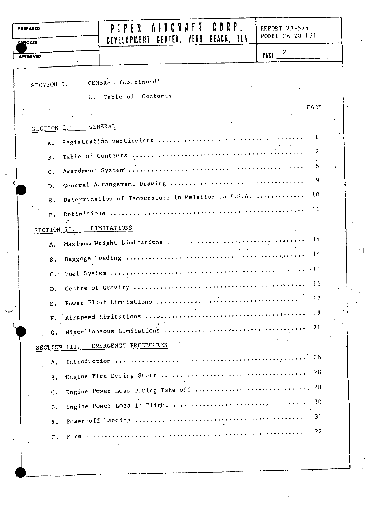
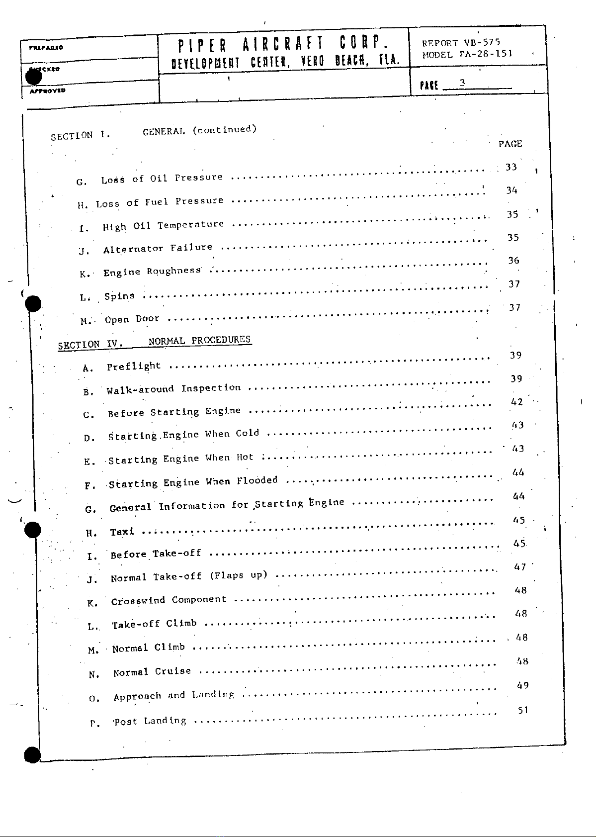
SECTION
.GENERAL
(continued)
PAGE
G.
Lo
S
of
Oil
Pressure
............................................
It.
Loss
of
Fuel
Pressure
............................................
34
1.
High Oil
Temperature
...................................
........
35
J. Alternator
Failure
.............................................
35
K.
Engine
Roughness
................................................
36
..... .. ... 37
~~L,
Spins
.. ............
M.
Open
Door
............
....
...................................
37
SECTION
IV.
NORMAL
PROCEDURES
•A.
Preflight
.........................
..............................
39
B.
Walk-around
Inspection
..........................
..............
39
C.
Before
Starting
Engine
..........
.............................
42
D. Starting.Engine
When
Cold
......................................
E Starting
Engine
When
Hot
..................................
43
F.
Starting
Engine
When
Flooded
................................
..... 44
a.
General
Information
for
Starting
Engine
.....................
44
H.
Taxi
............... ........................................
45
I.
Before
Takeoff.
.................................................
45
j.
Normal
Take-off
(Flaps
up).......................................
K.
Crosswind Component...............................................
48
L..
Takeoff
Climb..................................................
48
M.
Normal
Climb
....................................................
.. 48
N.
Normal
Cruise...................................................48
0.
Approach
and
Lndin
...........................................
49
p
Post
Landing
.......................................................
51