Robit S Sense User manual

Robit Sense Systems
Operator's Manual
Rig integrated deviation measurement system for Top
Hammer applications

Robit Oyj
Oyj Robit Plc
Vikkiniityntie 9
FIN-33880 Lempäälä, Finland
Tel. +358 (0)3 3140 3400
E-mail: [email protected]
Web: www.robitgroup.com
Business ID: 0825627-0
Introduction
2

Contents
1 Introduction.............................................................................................. 5
1.1 Operator's manual....................................................................................................................... 5
1.2 Reading instructions.................................................................................................................... 6
1.3 Copyright......................................................................................................................................6
1.4 Warranty...................................................................................................................................... 6
1.5 Customer service.........................................................................................................................6
1.5.1 Robit Sense support..........................................................................................................6
2 Safety.......................................................................................................7
2.1 General warnings.........................................................................................................................7
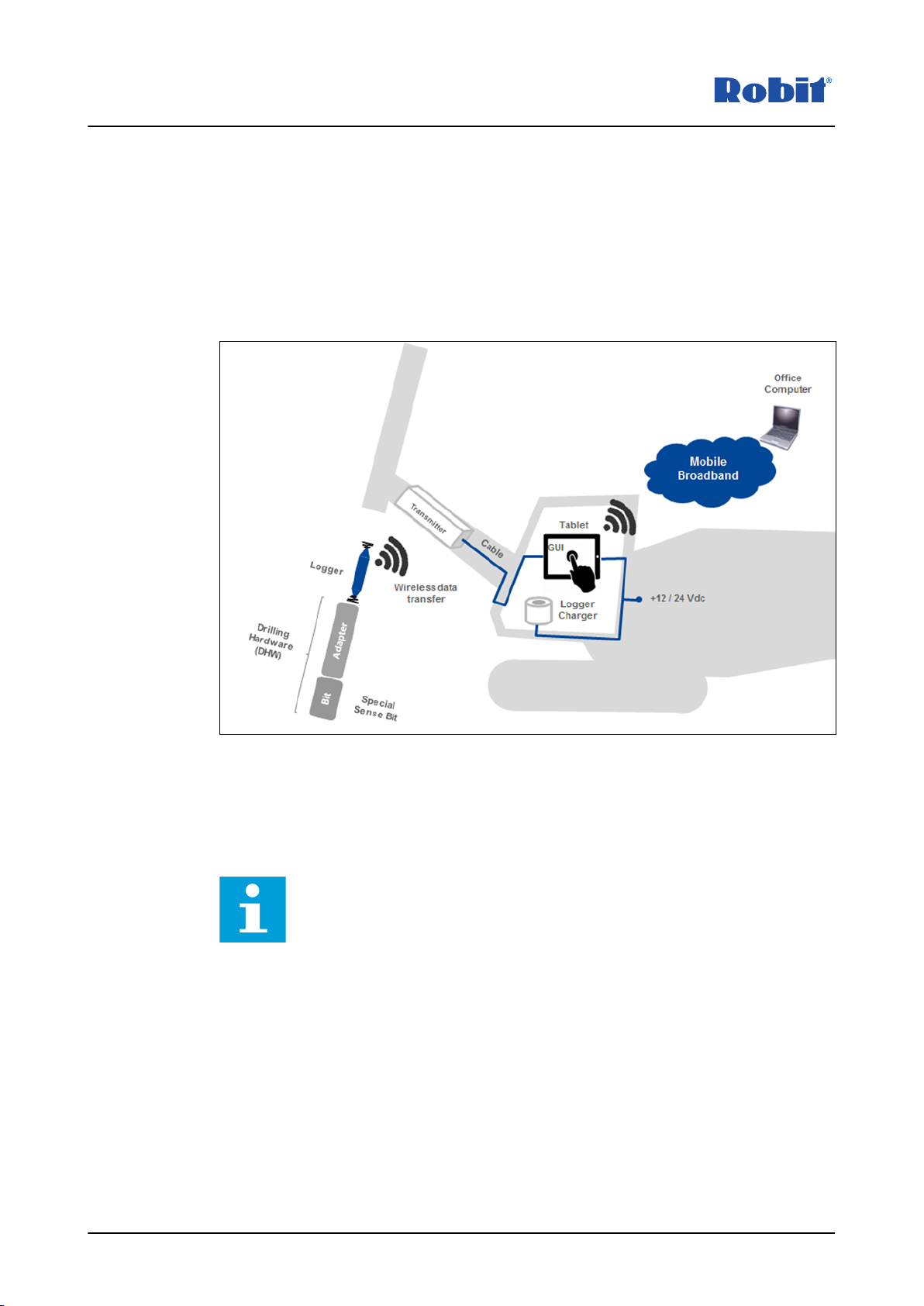
3 System description...................................................................................8
3.1 System components.................................................................................................................... 9
3.2 Operating principle.......................................................................................................................9
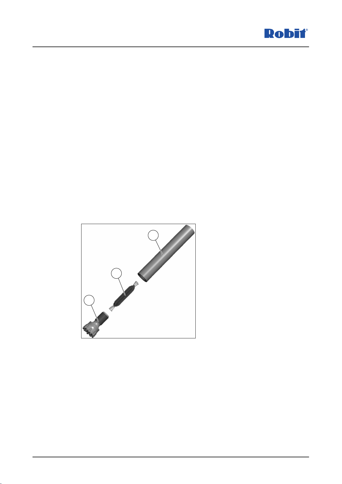
3.2.1 Measurement module and adapter................................................................................. 10
3.2.2 Transceiver..................................................................................................................... 11
3.2.3 Tablet computer.............................................................................................................. 11
3.2.4 Charging station..............................................................................................................11
3.3 User interface.............................................................................................................................12
3.3.1 Cloud synchronization.....................................................................................................12
3.4 Licensing....................................................................................................................................12
3.4.1 Registering a tablet......................................................................................................... 14
4 Operating instructions............................................................................ 17
4.1 Installing a measurement module..............................................................................................17
4.2 Starting up the software.............................................................................................................17
4.3 Measuring modes...................................................................................................................... 18
4.4 Measuring view..........................................................................................................................18
4.4.1 Measuring a borehole in continuous mode..................................................................... 19
4.4.2 Measuring a borehole in interval mode...........................................................................22
4.4.3 Measurement quality view...............................................................................................23
4.4.4 Modify measurement.......................................................................................................24
4.5 Results view...............................................................................................................................26
4.5.1 Inspecting measured holes............................................................................................. 26
4.6 Site view.....................................................................................................................................28
4.6.1 Creating a new field........................................................................................................ 28
4.6.2 Deleting a site, level or plan............................................................................................30
4.6.3 Additional information dialog...........................................................................................32
4.7 Settings view..............................................................................................................................32
5 Inspection and service........................................................................... 34
5.1 Daily inspections........................................................................................................................34
6 Troubleshooting..................................................................................... 35
6.1 Indicator lights on the transceiver circuit board..........................................................................35
Contents
59 - 002 - 06.03.2020 3

7 Environment and recycling.....................................................................36
7.1 Disposal of components.............................................................................................................36
8 Technical specifications......................................................................... 37
8.1 Standards...................................................................................................................................37
8.2 Licence information....................................................................................................................37
9 Certificates............................................................................................. 38
9.1 CE marking................................................................................................................................ 38
10 Appendices............................................................................................ 39
Contents
459 - 002 - 06.03.2020

1 Introduction
The Robit S Sense measurement system is used for measuring boreholes in rock drilling.
The measuring system may only be used for purposes for which Robit Plc has given its
written consent. The system may not be modified without Robit Plc's written consent. If
the system is modified, the plates and documents must be updated to correspond with
the new structure.
S Sense Hardware Package
The Robit S Sense standard delivery package contains the following:
• tablet computer
• transceiver
• docking station for the tablet computer
• 230 V power supply for the tablet computer
• 12/24 V power supply for the tablet computer
• charging station for measurement modules
• measuring software and accessories
• operator's manual.
S Sense Installation Package
The Robit S Sense installation package is customized for each drill rig type and contains
the following:
• all cables, cable ties and clamps for installation
• transceiver installation bracket
• ram mounts for the tablet computer's docking station.
S Sense Consumables Package
The Robit S Sense Consumables Package is delivered separately and contains the
following:
• four (4) measurement sensors
• two (2) adapters
• five (5) drill bits.
1.1 Operator's manual
Please study and observe the operator's manual thoroughly in order to maintain the
safety and reliability of the machine.
Robit Plc reserves the right to make changes.
For production-related reasons, the figures and technical specifications in this operator's
manual may deviate from the actual product.
Robit Plc cannot be held liable for any material damage or injuries caused by using the
device incorrectly or in violation of the instructions.
If you do not understand the instructions or some parts of this manual appear to be
missing, please contact Robit Plc.
Thank you for choosing Robit Plc as your systems supplier. We are confident that we will
fulfil your expectations regarding both usability and the availability of services.
Introduction
59 - 002 - 06.03.2020 5

Maintaining the operator's manual
Keep the manual in good condition and available to the operator and service personnel.
Ordering a manual
You can order a manual from Robit Plc's customer service or from our Robit retailer.
1.2 Reading instructions
Warnings
This manual contains warnings, which are indicated with yellow triangles and descriptions
of the warning.
Warning:
• Type of hazard!
• Provides a warning of a situation that may cause injury, death and
significant equipment or property damage if the appropriate safety
instructions are neglected.
• Provides information how to avoid the hazardous situation.
1.3 Copyright
This document may not be copied, presented or supplied to a third party or used for any
other purposes without Robit Plc's express permission.
Robit Plc reserves the right to change the values, equipment and service instructions
provided in the manual without advance notification.
1.4 Warranty
See the warranty information regarding Robit Plc's general warranty terms.
1.5 Customer service
Company name: Robit Plc
Address: Vikkiniityntie 9
FIN-33880 Lempäälä, Finland
Telephone / Telefax: +358331403400 / +35833670540
E-mail: [email protected]
WWW: https://www.robitgroup.com/contact-us/
1.5.1 Robit Sense support
Telephone / Telefax: +358143370412
E-mail: [email protected]
Introduction
659 - 002 - 06.03.2020

2 Safety
The purpose of the safety information is to reduce the number of accidents and prevent
personal injury and property damage.
Please read the safety instructions carefully and ensure that you are using the system in
a safe manner. Do not use the system in ways other than those described in this manual.
An incorrect method of use may be hazardous and cause an accident, fire or
electrocution.
You must also observe the instructions appearing on the computer screen and abide by
all warnings.
Do not operate the system if its components are damaged.
Use only components and accessories described in this manual.
2.1 General warnings
Warning:
• Electrocution hazard
• The power supply of the measurement module, which is available as
an accessory, provides a supply voltage of 230 V.
• Do not touch!
Caution:
• Burn hazard
• The adapter and drill bit can be hot after drilling. Touching hot
surface may cause personal injury.
• Wear protective gloves when attaching and detaching drill parts.
Caution:
• Lifting hazard
• The adapter and drill bit are heavy.
• Observe ergonomic lifting methods when attaching and detaching
drill parts.
Safety
59 - 002 - 06.03.2020 7

3 System description
For the purpose of calculating the size of demolition charges, it is important to know the
exact position, direction and deviation of the drilled holes.
The Robit S Sense system measures the deviation of the hole using inertial navigation
provided by gyroscopes and an accelerometer. The measurement is performed upon
lifting the drill, and the measurement data is transmitted to a computer in the cabin when
the rods are lifted.
Figure 1. System overview
The Robit S Sense system is easy to use, and it measures each hole you drill. The hole
measurement does not slow down drilling or interrupt it for the duration of the measuring.
The measurement results are available immediately after drilling. The system also
provides a wide range of tools for examining the holes and analysing the field.
Note: Borehole measurement accuracy is affected in certain borehole angles.
System azimuth accuracy decreases in red zones. Inclination accuracy is not
affected by the borehole angle.
System description
859 - 002 - 06.03.2020

10°
5°
10°
5°
3.1 System components
The Robit S Sense measuring system consists of the following components:
1. Measurement module
2. Adapter for the measurement module
3. S Sense compatible drill bit
4. Transceiver and cable
5. Tablet PC, dock, support and accessories
6. Measurement software
7. Measurement module charger and accessories
3.2 Operating principle
The Robit Sense measurement software is a versatile tool for measuring boreholes. The
measurement data can be saved in a database, where it can be viewed after drilling or at
a later time.
Holes can be measured in two ways: 1) select a site and field before measurement,
which allows you to define what hole to measure, or 2) drill and measure a hole first and
decide afterwards whether or not you wish to save it in a site. All holes measured in a
field can be viewed simultaneously, which provides a good overall view of the holes
throughout the field. A measured hole does not need to be connected to a worksite.
Instead, it can be saved in the database separately.
Selecting a field before drilling a hole
1. Select the site, level and field.
2. Select the hole to be drilled.
3. Press the Drill here button.
4. Drill the hole normally.
5. Once the hole has been drilled, press the Start lifting the rods button.
6. Enter the starting angle and length of the hole.
7. Maintain the rod stationary for the time shown on the screen.
8. Mark rod replacement points using the rod replacement button.
9. Once the drill has been lifted, the hole measurement data is transferred to the
computer.
System description
59 - 002 - 06.03.2020 9

10. The data for the drilled hole is linked to the selected hole automatically.
Drilling without selecting a field
1. Press the Start drilling button.
2. Select the measurement module.
3. Press the Drill new hole button.
4. Drill the hole normally.
5. Once the hole has drilled, press the Start lifting the rods button.
6. Enter the starting angle and length of the hole.
7. Maintain the rod stationary for the time shown on screen.
8. Mark the rod replacement points using the rod replacement button.
9. Once the drill has been lifted, the hole measurement data is transferred to the
computer.
10. Attach the measurement data to the hole.
a. Download the data from the measurement module.
b. Select the worksite, level and field where the data is to be saved. If you do not
select a site for the hole, it will be saved independently in the database.
c. Select the hole from the drilled field.
d. Link the transferred information to the drilled hole.
3.2.1 Measurement module and adapter
AA
BB
CC
Figure 2. Measurement module and adapter
The measurement module (A) measures the drilled hole. The measurement module is
cast in a protective urethane case. The module features multiple motion detectors, a
transmitter, internal memory and a wirelessly-charged battery. To activate the module,
place it in the charging station.
The measurement module is installed inside the hollow adapter (B) between the drill bit
(C) and rod. The measurement module is protected by two springs when it is installed in
the adapter.
The measurement module uploads data to the cabin computer when it is in the vicinity of
the transceiver. The measurement data is deleted once it has been transferred to the
computer. If the transfer is unsuccessful, the data will remain on the module until it has
been transferred to the computer. The data in the measurement module's memory will not
be lost even if the battery is drained in the middle of the measurement.
System description
10 59 - 002 - 06.03.2020

The adapter must be attached to the drill bit in the correct position or it may break.
3.2.2 Transceiver
The transceiver is fastened to the dust collection box with a protective metal piece. The
transceiver communicates wirelessly with the measurement module. The transceiver
connected to the cabin computer with a USB cable. The USB connector is protected
inside the case.
If multiple transceivers are used in the area, their signals may become mixed. This may
interfere with the connection of the measurement modules to the transceiver.
The transceiver circuit board features indicator lights that illustrate the status of the
device. The positions and locations of the indicator lights are described in the
Troubleshooting section.
3.2.3 Tablet computer
The Robit Sense measurement system is operated by means of the computer's touch
screen.
3.2.4 Charging station
The measurement module's charging station charges the measurement module
wirelessly when the module is placed in the designated slot. The charging power and
charge of the measurement module battery can be viewed on the computer screen when
the module is in the charging station.
To activate a measurement module, place it in the charging station.
The charging station features two indicator lights that indicate the status of the charging
station. Table 1 presents all the possible statuses of the charging station.
Standby Charging Charging com-
plete
Error
Limited charging
power
Foreign object
Green light on Green light blink-
ing
Green light on Green light blink-
ing
Green light off
Red light on Red light off Red light off Red light blinking Red light blinking
The charging station takes its power from the USB port in the computer dock.
System description
59 - 002 - 06.03.2020 11

3.3 User interface
The user interface of the Robit Sense S system is designed to be used with a touch
screen or mouse. The Robit Sense measurement software can be used to design drilling
fields, measure drilled holes, and inspect and analyse measurements with a range of
powerful graphical view and tools.
Figure 3. Robit Sense measurement software
3.3.1 Cloud synchronization
The cloud synchronization icon briefly appears in the user interface when
data has been successfully synchronized with the Sense Cloud Service.
If the synchronization fails for some reason, the synchronization error icon
is displayed. This icon disappears after successful data synchronization.
3.4 Licensing
During startup, the software automatically checks that the current license is valid. The
license validity period is displayed at the bottom of the home screen.
If a license cannot be acquired automatically, the software prompts you to check the
availability of licenses.
System description
12 59 - 002 - 06.03.2020

Click the Check button.The software contacts the licensing server and checks if the tablet
is registered in the Sense Cloud.
If a license is available, the software displays the licensing information in a confirmation
window. Click Proceed.
If a license cannot be acquired, you need to enter the organizational registration code.
Click Submit to send the code.
Your Company Administrator can order the organizational registration code from
https://
www.sensesystems.com
.
System description
59 - 002 - 06.03.2020 13

If the licensing period has expired, an error message is displayed. Contact Robit Plc. for
more details.
3.4.1 Registering a tablet
If the tablet computer's measurement software asks for a registration code, log into
https://www.sensesystems.com
with your credentials and go to the
Company
view.
System description
14 59 - 002 - 06.03.2020

You will see a list of licences. Select an available licence to register the tablet with by
clicking the Register Tablet text. If the list does not have an available licence, contact
Robit personnel.
A window with a registration code will open.
Write or copy the code into the registration code field on the tablet computer's
Measurement UI Software. Click Submit to send the code.
System description
59 - 002 - 06.03.2020 15

Review your licence information on the tablet computer and click Proceed to start using
the software.
System description
16 59 - 002 - 06.03.2020

4 Operating instructions
Before first use
Ensure that the transceiver is installed correctly in the device and that the transmitter
cable is properly attached to the boom.
Ensure that the measurement module charging station is installed correctly in the cabin
and that the power cable is connected.
Ensure that the computer is installed correctly in the cabin and that it does not prevent
the use of other drill rig devices and instruments. Make sure that the computer does not
obstruct the visibility out of the cabin in a way that makes driving or operating the rig
dangerous.
4.1 Installing a measurement module
Figure 4. Installing a measurement module
Procedure
1. Detach the drill bit from the adapter.
2. Check that the measurement module has a spring at both ends.
3. Insert the measurement module in the adapter with the antenna facing down.
4. Ensure that the guide pin is above the antenna in the groove and that the antenna is
aligned with the communication window.
5. Attach the drill bit to the adapter.
4.2 Starting up the software
Procedure
1. Start up the Robit Sense software by tapping the software icon on the tablet
computer.
Operating instructions
59 - 002 - 06.03.2020 17

2. Once the software has been activated, enter the lengths of the rods in either metres
or feet.
Note: The first rod length must also include the additional components,
i.e. the first rod, the measurement module adapter and the drill bit.
Once the rod settings have been approved, the program moves to the home screen
where you can select the desired function.
4.3 Measuring modes
Two measuring modes are available in the S Sense software:
Continuous mode
for
normal drilling conditions and
Interval mode
for tough drilling conditions.
You can select the measuring mode in the Settings > Measurement settings view.
• In continuous mode, the measurement is continuously active and the operator records
timestamps at each rod length when the coupling is clamped for uncoupling. This
mode is suitable when threads uncouple easily and percussion and flushing are rarely
needed during the measurement process. The continuous mode is sensitive to correct
working methods.
• The interval mode is suitable for demanding ground conditions when threads get stuck
and percussion is often needed for uncoupling. The interval mode maximizes
accuracy in tough conditions.
4.4 Measuring view
The process of measuring a borehole is initiated in the measuring view. You can access
the measuring view with the Start drilling button in the home menu.
Operating instructions
18 59 - 002 - 06.03.2020

You can also access the measuring view by selecting the hole in the Site view and
clicking the Measure here button.
The measurement modules connected to the transmitter are shown in the measurement
module view. The view indicates the measurement module identifiers, battery charges,
the battery power of modules being charged and the position of the modules. Up to five
measurement modules can be connected to the transmitter simultaneously.
A module in the charging station can be identified by the charging power indicator shown
next to the battery charge status. Other modules can be identified by moving a module
and checking which module moves on the display.
You can view detailed information about the selected logger by clicking the measurement
module image.
4.4.1 Measuring a borehole in continuous mode
Procedure
1. Press the measurement module image to select a logger installed in the drill. Select
Drill a new hole to start drilling and measurement.
Operating instructions
59 - 002 - 06.03.2020 19

2. Enter the clamp altitude and hole length using the sliders or the + and - buttons.
Once the hole has been drilled, you can begin saving the measurement by pressing
the Start lifting the rods button.
3. Enter the initial angle and side inclination or azimuth values using the sliders or the +
and - buttons.
Operating instructions
20 59 - 002 - 06.03.2020
Table of contents
Other Robit Tools manuals
Popular Tools manuals by other brands

AME
AME 71600 Instruction manual & parts breakdown

Traditional Tool Repair
Traditional Tool Repair DTF-125 operating instructions

Pro's Kit
Pro's Kit FB-1601/ FB-1602 user manual

Equalizer
Equalizer NS12TI Operator's instruction manual

Band-it
Band-it S75099 quick start guide

Equalizer
Equalizer SG4TM Instructions for use

Equalizer
Equalizer TFA4TM Operator's instruction manual

Delta
Delta 34-184 instruction manual

Power Fist
Power Fist Metal Punch Kit user manual

Master cool
Master cool HYDRA-KRIMP operating instructions

Sparta
Sparta Huskie Tools PRO LINE IL-7NDBG Operator's manual

Cembre
Cembre CP1086-W-1000-KV Operation and maintenance manual