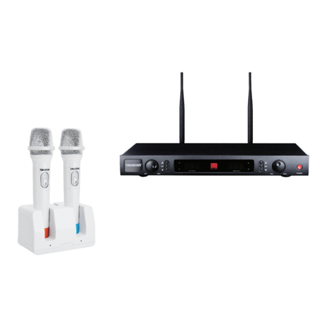
Takstar JD Series User manual

JD系列无线麦克风
JD Series Wireless Microphone System

前言
尊敬的用户:
感谢您选购得胜JD系列无线麦克风,为了您能够更好的了解使用本产品,建议您在使
用前仔细阅读本说明书。
若存在有疑问或者您有宝贵的建议,可通过拨打得胜官方服务热线400 6828 333或微信
扫描二维码关注得胜官方公众号与我们联系。
产品特性
JD系列无线麦克风
01
• 整个系统硬件电路由微电脑CPU控制,可以进行选频、显示、频率数据处理及自动频道追锁等功能;
• 釆用双液晶LCD显示,所有操作均可在液晶屏显示,方便用户了解系统工作状态及对系统进行设置;
• 所有发射机的电池电量可实时显示在各自的液晶显示屏上, 并在电池低电量时发出警告提示;
• 系统应用多种抗干扰技术,出厂时系统已预置多个互不干扰的频点,合理的设计,方便用户多系统同
时使用;
• 音频输出设有XLR平衡式插座输出和6. 3非平衡式插座输出两种方式,方便用户连接到不同的外部设
备上;
• 使用1U金属机箱,铝合金属面板,坚固美观及隔离谐波辐射的专业品质。
适用范围
适用演唱、会议、节目主持、演讲、户外活动等场合

02
JD-4H:
接收主机..................................................................................................................................................1台
会议底座..................................................................................................................................................4只
鹅颈咪杆..................................................................................................................................................4只
音频连接..................................................................................................................................................1条
电源适配..................................................................................................................................................1条
AA电池 ....................................................................................................................................................8节
UHF天线..................................................................................................................................................4条
角码.........................................................................................................................................................2个
说明书 .....................................................................................................................................................1本
JD-4D:
产品配置
接收主机..................................................................................................................................................1台
手持麦克风..............................................................................................................................................4只
音频连接线..............................................................................................................................................1条
电源适配器..............................................................................................................................................1条
UHF天线..................................................................................................................................................4条
AA电池 ....................................................................................................................................................8节
防滚圈 .....................................................................................................................................................4个
角码.........................................................................................................................................................2个
说明书 .....................................................................................................................................................1本
JD系列无线麦克风

03
接收机技术规格
综合特性
• 杂散抑制:N50dB
• 镜象抑制:N50dB
• 灵敏度:>25dBu (SIND=35dB)
• 音频输出电平:平衡输出(XLR output jack):250mV/600Q
非平衡输出(1/4" output jack):400mV/3KΩ
• 工作电压:DC 12V 工作电流:W350mA
• 机箱尺寸:480(宽)X 190(深)X 45(高)mm
• 频率范围:580-630MHz
• 频带宽度:60MHz
• 调制方式:FM调频
• 最大频偏:±45KHz
• 频率响应:75Hz-19KHz
• 信噪比(S/N):>60dB
• 失真度(IkDz):<5%
• 工作温度:TOP ~ 55°C
• 工作距离:100米(理想环境下)
• 消耗功率:7W
• 静态功率:2W
技术参数
发射器技术规格
• RF功率输出:最大30mW(国标电源)
• 振荡模式:PLL(数字频率合成器)
• 发射频率稳定度:<30ppm
• 动态范围:≥50dB(A)
• 频率响应:70Hz-19KHz
• 最大输入声压:130dBSPL
• 发射拾音头:动圈式
• 电 源:2节AA型碱性电池(预期使用时间约为8小时)
JD系列无线麦克风

04
功能示意
1.接收主机正面:
① 红外(IR)对频窗口:配合“SET”按键,将频率参数传至发射机,使接收机与发射机频率同步。
② 液晶显示屏:显示系统当前工作状态。
③ 上下按钮( ): 用于频率、音量调节等操作。
④ 确认按钮(SET): 按下可选择菜单选项,被选中菜单选项闪动显示。按下可确认调整当前选中的菜单选项。
⑤ 电源开关(POWER): 用于控制机内电源供应。
① 天线连接座D(ANT-D):用于连接外置天线。
② 平衡输出插座(BALANCED-D):采用“XLR”型插座,提供各通道独立信号输出。
③ 平衡输出插座(BALANCED-C):采用“XLR”型插座,提供各通道独立信号输出。
④ 天线连接座C(ANT-C):用于连接外置天线。
⑤ 天线连接座B (ANT-B):用于连接外置天线。
⑥ 平衡输出插座(BALANCED-B):采用“XLR”型插座,提供各通道独立信号输出。
⑦ 6.35mm非平衡混合输出插座(MIXED OUTPUT):将四路音频信号混合成一路输出。
⑧ 电源插座(DC INPUT):通过电源适配器为接收机供电。
⑨ 平衡输出插座(BALANCED-A):采用“XLR”型插座,提供各通道独立信号输出。
⑩ 天线插孔A(ANT-A):用于连接外置天线。
2.接收主机背面:
JD-4H
PROFESSIONAL WIRELESS MICROPHONE
JD-4H
PROFESSIONAL WIRELESS MICROPHONE
JD系列无线麦克风

05
① 麦克风金属网头。
② LCD显示屏:显示当前工作频道和电池电量。
③ 红外对频:和接收机上红外对频等对应来完成对频。
④ 开机键:点按开机,长按关机。
使用时注意不要遮挡天线,以免影响使用距离。
① 4插针话筒输入插座:用于安装及拆卸麦克风咪杆。
② 液晶显示屏:显示工作频率、电池电量等信息。
③ 电源开关:点按开机,开机后点按静音/取消静音,长按关机。
④ 电池仓:用于安装5号电池。(注意电池放置极性)
⑤ 红外对频窗口:配合接收机“SET”键,将频道参数传至发射器。
JD系列无线麦克风
3.手持发射机:
4.会议发射机:

06
使用说明
1. 手动频率调节:
打开接收机电源开关,在初始界面下,先短按“SET”按键。
② 然后点击对应通道的“▲”键与“▼”键调整到所需频率。
③ 当已调整到需要使用的频率时,再点按“SET”按键,显示屏闪烁并出现“IR-”字样表示已进入对频状
态,此时打开发射机电源开关,将发射机的红外(IR)窗口与接收机红外(IR)窗口呈直线相对(对频距
离可选择在10cm-30cm之间),待发射器显示频率跟接收机的频率一致,且对着麦克风说话有声音时,则
表示对频成功;如对频不成功可重新点按“SET”键重复以上操作,直至对频成功。
①
2. 自动扫频操作:
打开接收机电源开关,在初始界面下,先长按“SET”键,然后点按一下对应通道的“▲”或“▼”键。
② 接收机的对应通道会进入自动扫描状态,频率会跳动,当扫描到干净频点时,接收机会自动发出红外对
频状态,这时打开发射机电源开关,将发射机上的红外(IR)窗口对准接收机上的红外(IR)窗口即可。
①
JD系列无线麦克风

07
使用建议
1.安置接收机
① 从包装箱中取出接收机后,将4支接收天线连接到接收机的天线插口(ANT),并调节2支天线为顶部向上
并与地面基本垂直的方向。本接收机为真分集自动选讯的产品,接收机具备4支接收天线,并且内部具备4
套完整的接收电路和分集控制电路,每2支接收天线和2套接收电路负责1支麦克风信号的接收。对于每一
支麦克风来说,接收机的2支接收天线处在不同的位置,所接收的麦克风信号会有明显差别,分集控制电
路会自动比较和选择使用信号较强的一路,以消除接收时的盲区。
② 建议勿将接收机置于金属机柜中,金属机柜会屏蔽射频信号,影响接收距离。
③ 应该避免将接收机与影碟机,电脑,点歌机,音频处理器,LED大屏,大屏处理器,LED灯具和灯光控
制处理设备放在一起,它们发出的杂散干扰信号也会影响接收距离。
④ 接收机应尽量接近演出区,并且与大的金属物、墙面、脚手架、天花板等物体至少保持1.5米的距离,并
尽量保证麦克风与接收机之间有空旷的信号直射途径。
⑤ 请在离开接收机3米以外使用麦克风,使用过程中,各麦克风之间不可靠的太近,保持30cm以上的间距。
2.检查与接通电源
请先检查确认接收机的电源适配器规格与市电规格相符,如不相符,请停止安装与使用,并联络你的经销
商。否则将可能损坏机器,并有可能导致危险。
确认电压规格相符后,将电源适配器的输出插头插入接收机背面的"DC INPUT"插孔,并将适配器插入市电
插座。
3.工程安装调试方法
同区域多套使用时,其安装调试方法如下:
① 先打开一台接收机,麦克风都不开启,观察接收机第一通道RF信号指示是否有信号,如有信号,表示
有干扰信号,则进行调节到没信号指示状态。
② 打开麦克风,确保第一支麦克风在实际使用位置工作正常。
③ 第一只麦克风保持打开状态,观察第二通道RF信号指示状态(重复第一通道的操作确认没干扰信号)
④ 开启第二支麦克风,确保第二支麦克风在实际使用位置工作正常,之后一次类推,保证调试好的麦克
开启状态,重复第②③④步直到所有话筒调试完毕。
⑤ 按照以上步骤调试完成后,每次只关闭一支麦克风,查看对应通道的RF指示灯是否有信号显示,(正
常是不会有信号显示的,如果有信号显示就继续更换频率),这样把每个通道再检查一遍,
一般一遍基本可达到使用要求。
JD系列无线麦克风

08
如果有麦克风损坏或者丢失,需要补充,请用备品麦克风与接收机进行对频操作后即可使用。
4.注意事项
大的金属体、墙面、天花板等反射物,以及人体等遮蔽物,将减弱麦克风的直射信号
② 避免与有可能产生强电磁场的设备安装在一起,如微波炉、电磁炉、电动机、发电机等;
③ 尽量远离开关电源电路、射频电路、高频脉冲电路,如:LED大屏幕、大功率电台、对讲机、高压发生
器、负离子发生器等。重点说LED大屏幕,因内部有数量众多的开关电源,极易影响接收机的工作;
④ 不要与其他设备,特别是有开关电源的设备、发射设备安装在同一个机柜内,比如DVD播放机、点歌机、
设备的电源变压器、开关电源等;4、 安装无线话筒时遵循独立的原则,尽量远离其他设备,小型电磁干扰
源基本相隔50公分以上就相对安全了,大型干扰源如LED屏幕的话,一般超过5米以上相对安全;
⑤ 麦克风越远信号越弱,麦克风与接收天线之间障碍越多,信号越弱。
① ;
JD系列无线麦克风

产品尺寸图示
1.接收主机:
2.手持发射机: 3.会议发射机:
09
JD系列无线麦克风

安全警示
为避免电击、高温、着火、辐射、爆炸、机械危险以及使用不当等可能造成的人身伤害或财产损失,使用
本产品前,请仔细阅读并遵守以下事项:
1.使用产品时请确认所连接设备与本产品功率是否匹配以及合理调整设备音量大小,不要在超过产品功
率及大音量下长时间使用,以免造成产品异常;
2.使用中若发现有异常(如冒烟、异味等),请立即关闭电源开关并拔掉电源插头,然后将产品送经销
商检修;
3.本产品及附件都应放置在室内干燥通风处,勿长期存放在潮湿、灰尘多的环境,使用中避免靠近火源,
雨淋、进水、过度碰撞、抛掷、振动本机及覆盖通风孔,避免损坏其功能;
4.若产品需要固定于墙壁或天花板上时,请确保固定到位,防止因固定强度不足导致产品发生跌落危险;
5.使用该产品时需遵守相关安全规定,法律法规明确禁止使用场合请勿使用产品,以免导致意外事故;
6.请不要自行拆机改装或维修,以防止出现人身伤害,如有问题或服务需求请联系当地经销商跟进处理。
关于本说明书
本说明书中内容符合截止印刷之日的技术规格。由于得胜公司会不断改进产品,本说明书可能不符合您的
特定产品的技术规格。要获取最新版说明书,请访问得胜官网,然后下载说明书文件。技术规格、设备或
另售的附件在各个地区可能有所不同,如有问题请与当地得胜经销商确认。如需更多支持和深层产品信息,
请浏览得胜官方网站:https://www.takstar.com/
10
JD系列无线麦克风

Preface
Dear Customer,
Thank you for purchasing Takstar JD Series Wireless Microphone System. In order to better understand
and use the product, please read this manual carefully. If you have any questions or suggestions,
please contact our local dealer.
Features
Applications
For performance, conference, program host, speech, outdoor activity
• Microcomputer controlled system, featuring frequency selection, LCD display, frequency data
processing and automatic channel scan.
• On-board LCD display makes it easier to track system status and modify system settings.
• Transmitter battery level meter on receiver LCD screen, with low-power alert function.
• Adopts a variety of anti-interference technologies, comes with multiple non-interfering frequency
presets, convenient for using several systems together.
• XLR balanced outputs and 6.3 unbalanced outputs, for connecting different external devices.
• 1U rack-sized metal chassis, aluminum alloy panel, sturdy, isolating harmonic radiation.
11
JD Series Wireless Microphone System

12
Package Contents
JD-4D
1 × Receiver
4 × Handheld Mic
1 × Audio Cable
1 × Power Adapter
4 × UHF Antenna
8 × AA Battery
4 × Anti-Roll Ring
2 × Angle Bracket
1 × User Manual
JD-4H
1 × Receiver
4 × Conference Mic Base
4 × Gooseneck Mic
1 × Audio Cable
1 × Power Adapter
8 × AA Battery
4 × UHF Antenna
2 × Angle Bracket
1 × User Manual
JD Series Wireless Microphone System

13
Specifications
Transmitter
Receiver
Overall System Parameters
• RF Power Output: 30mW max
• Oscillation Mode: PLL (digital frequency synthesizer)
• Transmission Frequency Stability: <30ppm
• Dynamic Range: ≥50dB(A)
• Frequency Response: 70Hz-19KHz
• Max Input SPL: 130dBSPL
• Capsule: Dynamic
• Power Supply: 2PCS AA alkaline batteries (expected use time is about 8hrs)
• Spurious Suppression: N50dB
• Image Rejection: N50dB
• Sensitivity: >25dBu (SIND=35dB)
• Audio Output Level: balanced output (XLR output jack): 250mV/600Q
unbalanced output (1/4" output jack): 400mV/3KΩ
• Working Voltage: DC 12V; Working Current: W350mA
• Chassis Size: 480 (W) × 190 (D) × 45 (H) mm
• Frequency Range: 580-630MHz
• Frequency Bandwidth: 60MHz
• Modulation Method: FM
• Max Frequency Deviation: ±45KHz
• Frequency Response: 75Hz-19KHz
• Signal-To-Noise Ratio (S/N): >60dB
• Distortion (IkDz): <5%
• Operating Temperature: TOP ~ 55°C
• Working Distance: 100 meters (under ideal conditions)
• Power Consumption: 7W
• Static Power: 2W
JD Series Wireless Microphone System

Function Descriptions
14
① Infrared (IR) Sync Window: transmit frequency parameters to the transmitter to sync transmitter
with receiver frequency, by using the “SET” button.
② LCD Display: display the system working status.
③ Up/Down Buttons ( ): used mainly for frequency and volume adjustment.
④ Confirmation Button (SET): press it to start or confirm menu selection.
⑤ Power Switch (POWER): used for power supply control of the device.
① Antenna Connector D (ANT-D): used to connect an external antenna.
② Balanced Output Socket (BALANCED-D): XLR connector; signals of each channel are output separately.
③ Balanced Output Socket (BALANCED-C): XLR connector; signals of each channel are output separately.
④ Antenna Connector C (ANT-C): used to connect an external antenna.
⑤ Antenna Connector B (ANT-B): used to connect an external antenna.
⑥ Balanced Output Socket (BALANCED-B): XLR connector; signals of each channel are output separately.
⑦ 6.35mm Unbalanced Mixed Output Socket (MIXED OUTPUT): signals of all four channels are mixed
into one output.
⑧ Power Socket (DC INPUT): accept power supply to the receiver via a power adapter.
⑨ Balanced Output Socket (BALANCED-A): XLR connector; signals of each channel are output separately.
⑩ Antenna Connector A (ANT-A): used to connect an external antenna.
1. Receiver Front Panel
2. Receiver Rear Panel
JD-4H
PROFESSIONAL WIRELESS MICROPHONE
JD-4H
PROFESSIONAL WIRELESS MICROPHONE
JD Series Wireless Microphone System

15
① Mic Metal Grille
② LCD Display: shows the current working channel and battery level.
③ Infrared Pairing: pair with the corresponding infrared receiver to complete the pairing process.
④ Power Button: press to turn on the mic, long-press to turn it off.
When using, please avoid obstructing the antenna to prevent any interference with the operating
distance.
.
JD Series Wireless Microphone System
3. Handheld Microphone

16
Front
① 4-Pin Mic Input Socket: used to install and remove the pluggable mic.
② LCD Display: display information such as operating frequency and battery power.
③ Power Switch: press to power up, then press to mute/unmute, and press and hold to power off
the mic.
④ Battery Compartment: used to install 2PCS AA alkaline batteries. (Please observe battery polarity)
⑤ Infrared Sync Window: receive frequency parameters from receiver, by using the “SET” button
on receiver.
JD Series Wireless Microphone System
4. Conference Transmitter
RearBottom

17
Operation Instructions
1. Manual Frequency Adjustment:
Switch on the receiver power. On default home screen, press "SET" button once
② then press "
③
power up the transmitter, align both IR windows on the transmitter and the receiver within
10cm-30cm, and wait until the frequency shown on the transmitter changes to the receiver frequency.
If synced successfully, there should be AF audio signal when you talk to the mic. If failed to sync,
please retry all the afore steps.
① .
▲" or "▼" button on the respective channel to adjust to a desired frequency.
Next, press “SET” again to start pairing, the LCD screen will flicker and show "IR-". Meanwhile,
2. Automatic Frequency Scan:
Switch on the receiver power. On default home screen, press and hold “SET” button, then press
"▲" or "▼" button on the respective channel.
② The receiver will start automatic frequency scan, and the screen will flicker as it scans. When it finds
the cleanest frequency available, the receiver will begin IR sync automatically. Meanwhile, power up
the transmitter, align both IR windows on the transmitter and the receiver to complete syncing.
①
JD Series Wireless Microphone System

18
Recommendations for Use
1. Placement of the Receiver
① After unpacking the receiver, connect the four receiver antennas to the antenna ports (ANT) on the
receiver. Adjust two of the antennas to face upward at the top and be approximately vertical to the
ground. This receiver is equipped with true diversity automatic selection. It has four receiver
antennas, along with four complete sets of receiving circuits and diversity control circuits. Each pair
of antennas and receiving circuits is responsible for receiving signals from one mic. For each mic, the
two receiver antennas are positioned differently, resulting in noticeable differences in the received
mic signals. The diversity control circuit will automatically compare and select the stronger signal,
eliminating blind spots during reception.
② It is recommended not to place the receiver inside a metal cabinet as it can shield RF signals and
affect the reception distance.
③ Avoid placing the receiver near DVD players, computers, karaoke machines, audio processors, LED
displays, display processors, LED lighting fixtures, and lighting control devices. The stray interference
signals emitted by these devices can also affect the reception distance.
④ The receiver should be placed as close to the performance area as possible and should maintain
a distance of at least 1.5 meters from large metal objects, walls, scaffolding, ceilings, and other
objects. Additionally, ensure there is a clear signal path between the mic and the receiver.
⑤ Please use the mic at a distance of at least 3 meters from the receiver. During usage, maintain a
minimum distance of 30cm between each mic.
2. Checking and Connecting the Power
Before proceeding, please ensure that the power adapter specifications of the receiver match the
local power specifications. If they do not match, please refrain from installing and using the
equipment and contact your dealer. Otherwise, it may cause damage to the device and pose
potential risks.
Once you have confirmed the voltage specifications, insert the output plug of the power adapter into
the DC INPUT socket located on the back of the receiver. Then, plug the adapter into a power outlet.
3. Installation and Setup Procedures
When multiple sets are used in the same area, follow the installation and setup procedures below:
① Start by turning on one receiver without activating any mics. Observe the RF signal indication of
JD Series Wireless Microphone System

19
there is no signal indication.
② Turn on a mic and ensure that the first mic is functioning properly in its actual operating position.
③ Keep the first mic open and observe the RF signal indication of the second channel (repeat the
steps from the first channel to confirm the absence of interference signals).
④ Activate the second mic and ensure its proper functioning in its actual operating position. Repeat
this process for subsequent mics, ensuring that the previously set mics remain open. Repeat steps 2,
3, and 4 until all mics have been set up.
⑤ After completing the above steps, individually turn off each mic and check if the corresponding
channel's RF indicator shows any signal (normally, there should be no signal indication. If there is a
signal indication, continue to change the frequency.) Repeat this check for each channel.
If there is a need to replace mics due to damage or loss, simply use spare mics and perform frequency
pairing with the receiver.
the first channel on the receiver. If there is a signal present, it indicates interference. Adjust until
4. Precautions
① Large metallic objects, walls, ceilings, and other reflective surfaces, as well as human bodies, can
weaken the direct signal of the mic.
② Avoid installing the mic system near devices that may generate strong electromagnetic fields, such
as microwave ovens, induction cookers, electric motors, generators, etc.
③ Stay away from switch power circuits, RF circuits, and high-frequency pulse circuits, such as LED
screens, high-power transmitters, walkie-talkies, high-voltage generators, ion generators, etc. LED
screens, in particular, contain numerous switch power supplies that can significantly affect the
operation of the receiver.
④ Do not install the wireless mic system in the same cabinet as other devices, especially those with
switch power supplies or transmitters, such as DVD players, karaoke machines, power transformers
of equipment, switch power supplies, etc. When installing the wireless mic, follow the principle of
isolation and try to keep a distance of at least 50 centimeters from other devices that may cause
electromagnetic interference. For larger interference sources like LED screens, it is generally safer to
maintain a distance of over 5 meters.
⑤ The signal strength of the mic weakens as the distance between the mic and the receiving antenna
increases, especially in the presence of obstacles between them.
JD Series Wireless Microphone System
Table of contents
Other Takstar Microphone System manuals