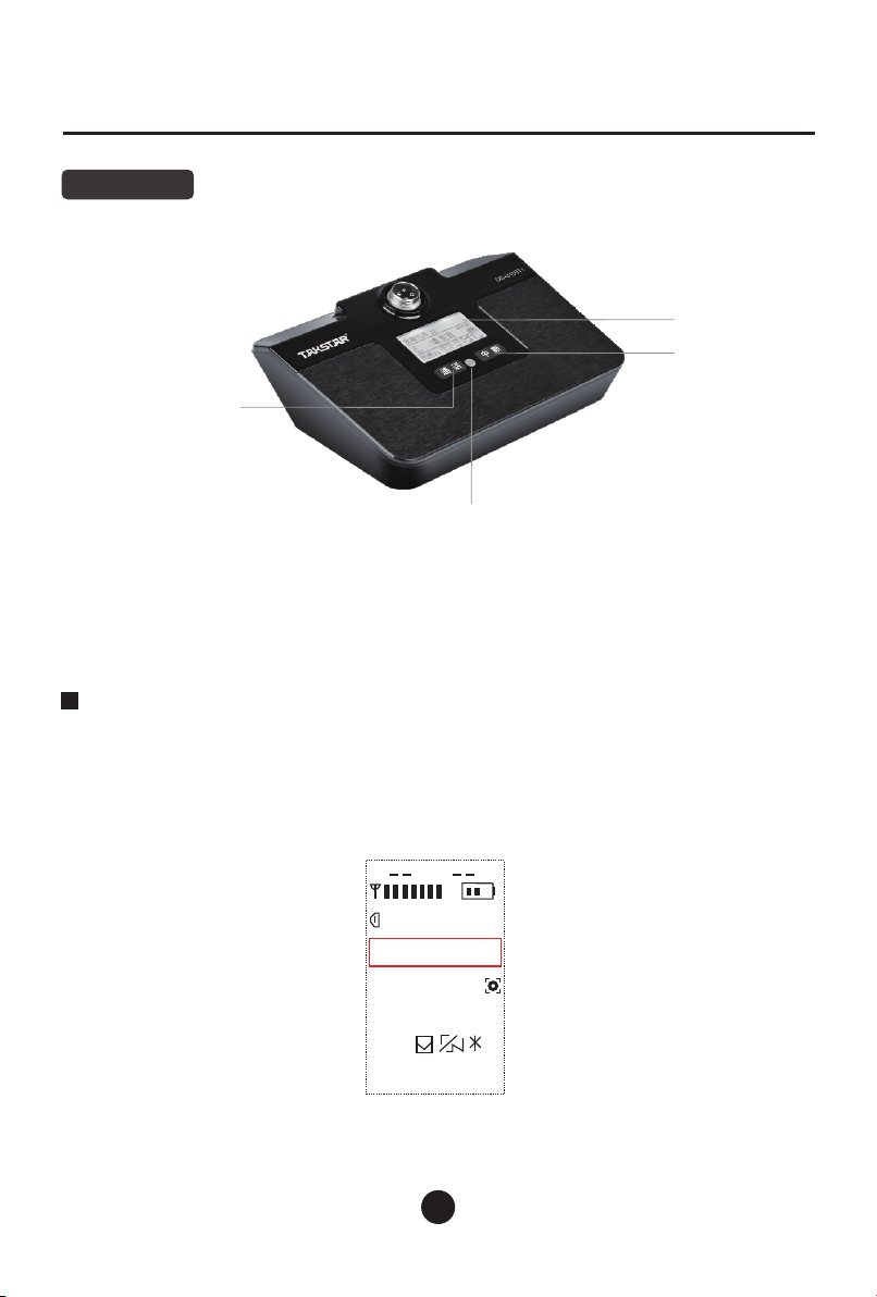
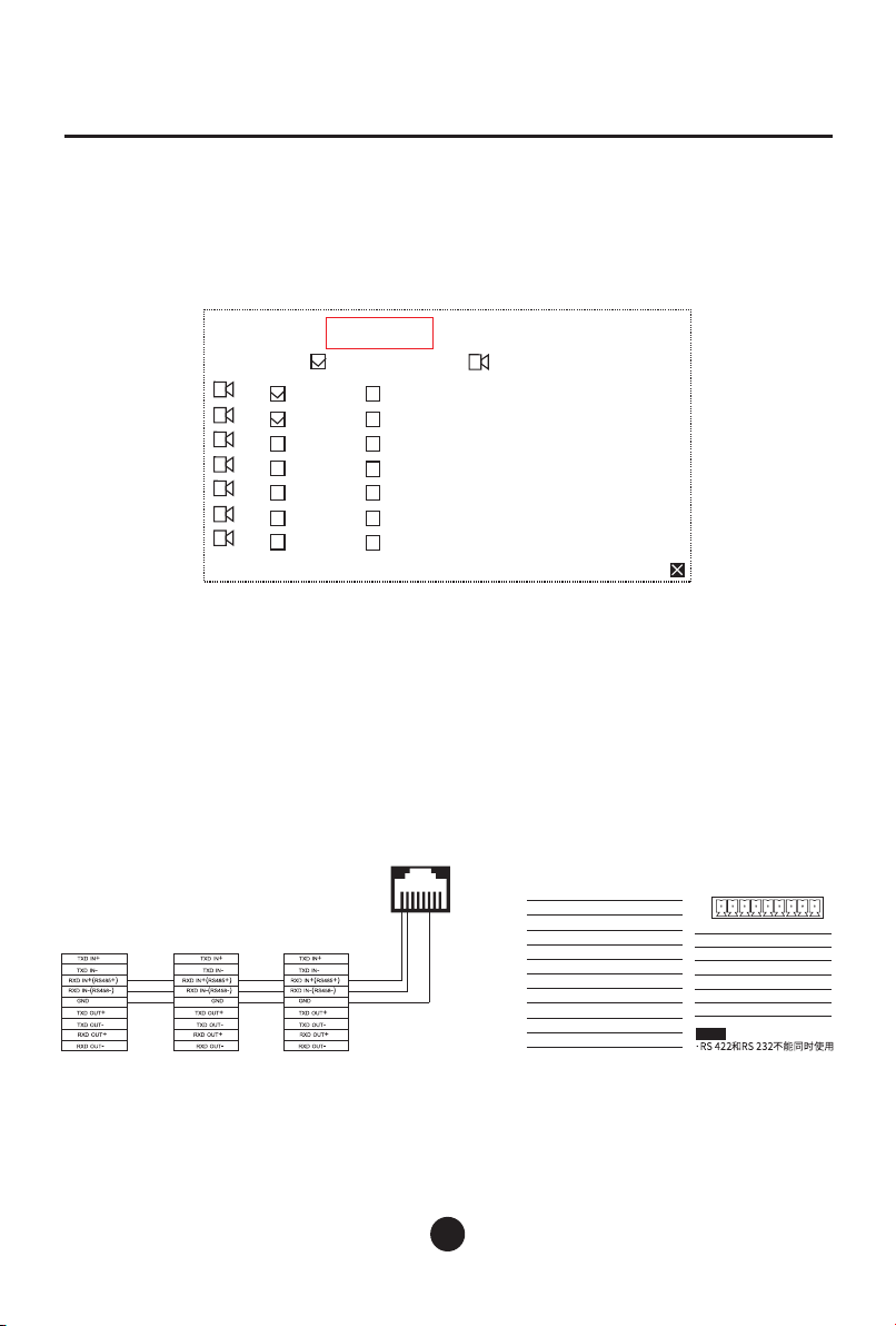
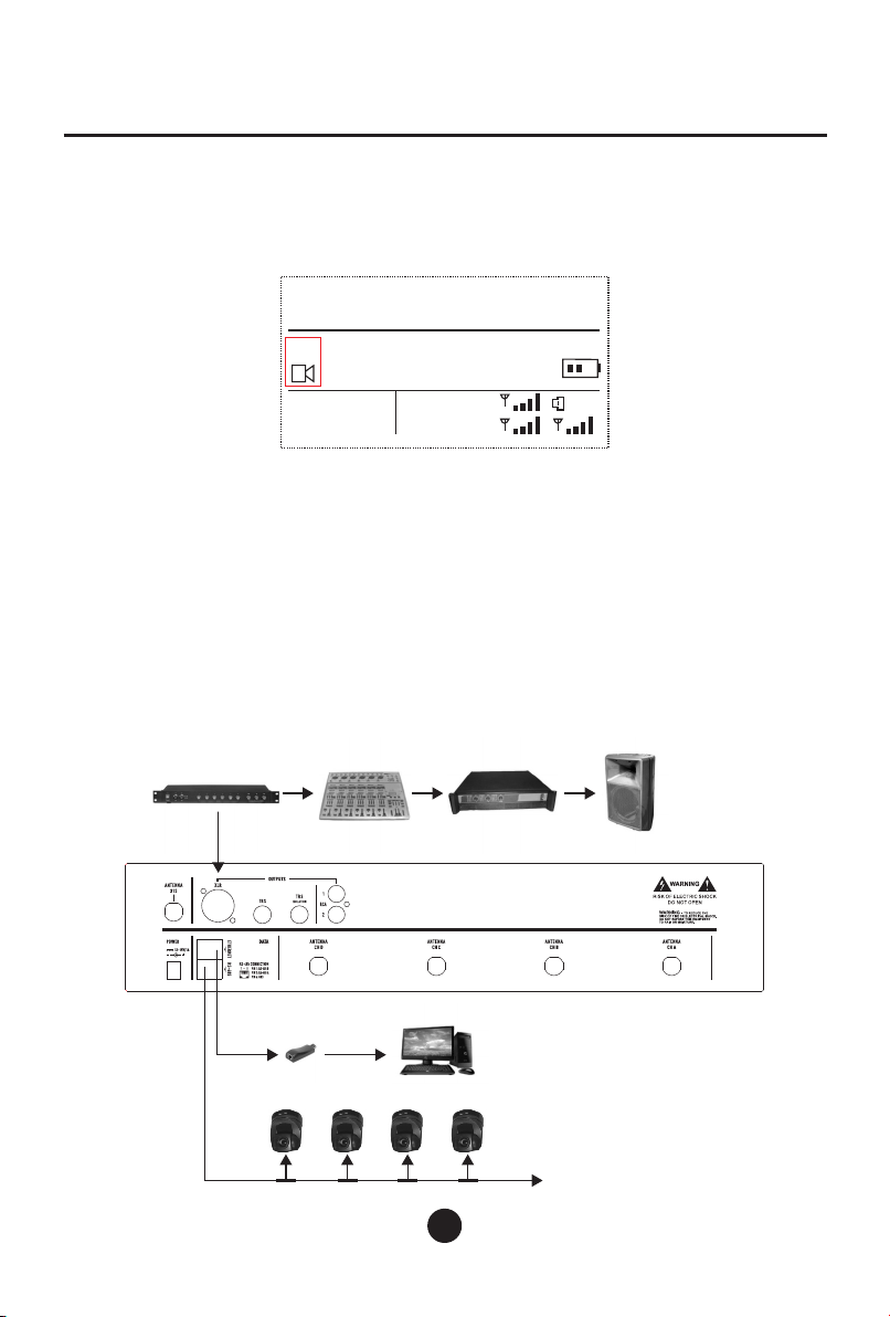
Takstar DG-U100 User manual
Other Takstar Microphone System manuals

Takstar
Takstar E210 User manual

Takstar
Takstar DA-235M User manual

Takstar
Takstar JD Series User manual

Takstar
Takstar DG-U100 User manual

Takstar
Takstar WGV-601 User manual

Takstar
Takstar TS-6320 User manual

Takstar
Takstar SGC-200W User manual

Takstar
Takstar UHF User manual

Takstar
Takstar VF-289 User manual
Popular Microphone System manuals by other brands


Sennheiser
Sennheiser Evolution Wireless Digital EW-DX EM 2 quick guide

Alpha Technologies
Alpha Technologies RBMS Installation & operation manual

SWIT Electronics Co.,LTD.
SWIT Electronics Co.,LTD. CW-S150 user manual

Shure
Shure UA844 user guide

Panasonic
Panasonic SHFX70 - DVD HOME THEATER WIRELESS SYSTEM operating instructions

Pyle
Pyle PDWM5000 user manual