TALARIA STING TL3000 User manual

LLEXETER.CO.UK
LLEXETER LTD - UNITS 15-18 GREENDALE BUSINESS PARK - WOODBURY SALTERTON - DEVON - EX5 1EW - UNITED KINGDOM
COMPANY NO: 4940600 / VAT REGISTRATION NO: GB825156925 TEL: 01395 233128
Motorcycle Service
Manual
Models Covered;
TL3000 - Off Road
TL45 - On Road

LLEXETER.CO.UK
LLEXETER LTD - UNITS 15-18 GREENDALE BUSINESS PARK - WOODBURY SALTERTON - DEVON - EX5 1EW - UNITED KINGDOM
COMPANY NO: 4940600 / VAT REGISTRATION NO: GB825156925 TEL: 01395 233128
All rights reserved. No parts of this publication may be reproduced, stored in
a retrieval system, or transmitted in any form or by any means, electronic or
mechanical photocopying, recording or otherwise,without the prior written
permission of LLexeter Ltd, UK
No liability can be accepted for any inaccuracies or omissions in this publication,
although every possible care has been taken to make it as complete and accurate
as possible.
We reserve the right to make changes at any time without prior notice and without
incurring an obligation to make such changes to products manufactured previously.
See your Motorcycle dealer for the latest information on product improvements or
alterations incorporated after this publication.
All information contained in this publication is based on the latest product
information available at the time of publication. Illustrations and photographs in this
publication are intended for reference use only and may not depict actual model
component parts.
All content compiled or created by Colin Price
First edition August 2022
Second edition August 2022
Contents;
1 General Information
2 Front wheel, Steering and Suspension
3 Rear wheel and Rear Suspension
4 Braking system
5 Electronic Power-train
6 Electric Motor and Gearbox
7 Bodywork & Chassis
8 Component Locations & Wiring Diagram

LLEXETER.CO.UK
LLEXETER LTD - UNITS 15-18 GREENDALE BUSINESS PARK - WOODBURY SALTERTON - DEVON - EX5 1EW - UNITED KINGDOM
COMPANY NO: 4940600 / VAT REGISTRATION NO: GB825156925 TEL: 01395 233128
1 General Information
e road-going Sting is largely the same as its dirty sibling with same centrally-mounted 3000-watt electric
motor, brakes, wheels, tyres, and fully adjustable suspension including DNM front suspension and Fastace
rear mono-shock.
e 60V, 38Ah lithium-ion battery can be charged in just 4 hours from any standard 3-pin UK plug socket.
It’s fully removable and can be taken out of the bike in a matter of seconds.
Model Characteristics
Drive System: Chain and Sprockets
Front Suspension: DNM USD Telescopic Rear suspension: Fastace Mono-shock
Wheel Base: 1250mm
Overall Length: 1890mm
Overall Width: 815mm Front brake: Hydraulic
Overall Height: 1155mm Rear Brake: Hydraulic
Overall Mass in Running
Order: 55kg Maximum mass on
Front wheel: 67kg
Maximum Allowed Mass
inc. rider: 168kg Maximum mass on Rear
wheel 101kg
Model Identification (VIN Prefix): R73TL3A00M??????
Service information
Model Code: TL45 Sting L1e
TL3000 Sting Motor Type; Talaria 182ZW6043407NA
Motor Rated Power; 3000w Motor Peak Power; 3700w @ 2100rpm
Oil Grade; CL-5 Oil Type; Hypoid
Oil Viscosity; 85w/90 Oil Quantity; 120-150ml
DNM Fork Oil Grade; 15w DNM Fork Oil Quantity; 130ml
DNM Front Fork Air Pressure; 100-150psi
Brake Fluid Type; Mineral Oil Battery Type; Lithium 60v 38Ah
Tyre Pressures;
Front; 32psi Rear; 32psi

LLEXETER.CO.UK
LLEXETER LTD - UNITS 15-18 GREENDALE BUSINESS PARK - WOODBURY SALTERTON - DEVON - EX5 1EW - UNITED KINGDOM
COMPANY NO: 4940600 / VAT REGISTRATION NO: GB825156925 TEL: 01395 233128
Component
Nm
Bolt Size
Component
Nm
Bolt Size
Belly pan Bolts 7
M6 x 10mm x 2
M6 x 20mm x 2
(with nuts)
Handlebar Mounting Pinch Bolts 15 M8 x 22mm
Brake Pad Retaining Pins 5 Horn Cover Bolts 5 M5 x 10mm x 1
M5 x 14mm x2
Chain Guard Bolts 5 M6 x 14mm Horn Securing Bolt 5 M5 x 10mm
Chain Guard Mount Bolts 5 M6 x 14mm Ignition Switch Bolts 5 M5 x 10mm
Circuit Breaker Bolts 5 M3 x 35mm Left Engine Cover Bolts 5 M6 x 10mm
DC-DC Converter Bolts 7 M6 x 11mm Mirror Assembly Handlebar Fittings 10-20
Engine Mounting Bolt (Rear) 55 M10 x 80mm Mirror Assembly Pinch Bolts 8 M6 x 20mm
Engine Mounting Bolts (Left side) 40 M8 x 75mm, 51mm spacer
M8 x 80mm, 60mm spacer
Number Plate Bracket Bolts 5
8
M5 x 11mm x 2
M6 x 14mm
Engine Mounting Bolts (Right side) 35 M8 x 25mm Rear Brake Caliper Bolts 10 M6 x 18mm
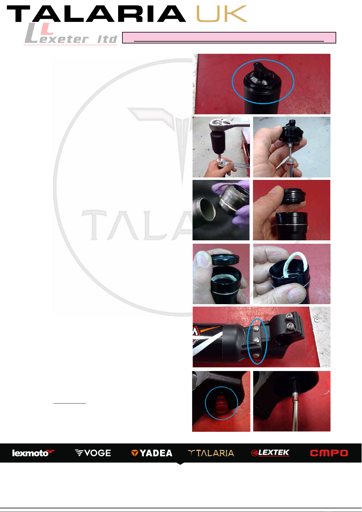
Fork Cap to Damper Rod fitting 15 Thread Lock Rear Brake Caliper Bolts 10 M6 x 18mm, Thread Lock
Front Brake Caliper Bolts 10 M6 x 18mm Rear Brake Disc Bolts 12 M6 x 12mm, Thread Lock
Front Brake Caliper Mounting Bracket 12 M6 x 24mm Rear Brake Hose Guide (Swingarm) 5 M6 x 7mm
Front Brake Disc Bolts 8 M5 x 10mm, Thread Lock Rear Brake Master Cylinder Clamp Bolts 7 M5 x 16mm
Front Brake Hose Guide (Fork) 5 M4 x 17mm Rear Fairing Undertray/Cover 7
4
M6 x 14mm x 5
Screw x 4
Front Brake Master Cylinder Clamp Bolts 7 M5 x 16mm Rear Mudguard (Swingarm) Bolts 5 M6 x 14mm
Front Fork Caps 20 Rear Sprocket Bolts 30 M8 x 18mm, Thread lock
Front Fork Leg Guards 5 M5 x 8mm Rear Subframe Assembly 20 M8 x 20mm
Front Fork Lower Yoke Pinch Bolts 10 M5 x 16mm Rear Wheel Spindle 50 ± 5
Front Fork Top Yoke Pinch Bolts 7 M5 x 16mm Saddle Fittings 5 M6 nuts
Front Indicator Mount Bolts 7 M6 x 12mm Seat Cowling (Front) 5 M6 x 10mm
Front Mudguard Bolts 5 M6 x 14mm Seat Lock Bolts 5 M6 x 14mm
Front Wheel Spindle 15 M16 x 12mm Shock Absorber Lower Bolt 25-30 M8 x 60mm
Front Wheel Spindle Pinch Bolts 10 M5 x 15mm, Thread lock Shock Absorber Upper Bolt 30 M8 x 54mm
Gearbox Casing to Motor Bolts 12
5-7
M6 x 25mm x6
M6 x 8mm x 2
Speedometer Clamp Bolts 5 M4 x 12mm
Gearbox Cover Bolts 25 M8 x 34mm Speedometer Mount Bolts 5 M4 x 7mm
Gearbox Oil Drain Bolt 50 M16 x 12mm Speedometer Switchgear Bolts 5 M3 x 8mm
Handlebar Clamp Bolts 8 M5 x 12mm Steering Stem Crown Bolt 8 M6 x 30mm
Handlebar Left Switchgear Bolts 5 M5 x 22mm Suspension Linkage Bolts 25-30 M8 x 64mm Upper
M8 x 84 Lower
Handlebar Right Switchgear Bolts 7 M5 x 11 Swingarm Pivot Bolts 50-60 Thread Lock
Headlamp Bracket Bolts 8 M6 x 14mm Top Yoke Stem Pinch Bolt 10
Headlamp Mounting Bolts 8 M5 x 12mm
Torque Settings
Service Schedule
Talaria Sting Service Schedule
Interval 1 / Mileage
Interval 2
Interval 3
Interval 4
Interval 5
Repeating
(On & Off Road Versions)
3 Months / 250m
6 Months / 500m
12 Months / 1000m
18 Months / 1500m
24 Months / 2000m
Every 6 Months / 500m
Motor Controller
I IC I C C
Throttle play
IIIII I
Brake system
IIIII I
Drive Chain/ Belt
A/G A/G A/G A/G A/G A/G
Suspension
I CI C I C
Swingarm Suspension Link Bushes
I G I G I I/G
Tyres: pressure,damage, tread etc.
IIIII I
Bearings (wheels, suspension, swingarm)
IIIII I
Headrace Bearings
I G I G I I/G
Side stand saftety switch
IIIII I
All Fixings
IIIII I
Electrical system
IIIII I
Brake Fluid
I IR I R R
Gearbox oil
I IR I R R
A: Adjust
I: Inspect
R: Replace
C: Clean
G: Grease

LLEXETER.CO.UK
LLEXETER LTD - UNITS 15-18 GREENDALE BUSINESS PARK - WOODBURY SALTERTON - DEVON - EX5 1EW - UNITED KINGDOM
COMPANY NO: 4940600 / VAT REGISTRATION NO: GB825156925 TEL: 01395 233128
2 Front wheel, Steering and Suspension
Chapter Contents
2.1 : Front Wheel removal, inspection and rebuilding
2.2 : Front Suspension, Fork removal, inspection and rebuilding
2.3 : Yoke and Steering bearings, removal, inspection and rebuilding
2.3a : Removal
2.3b : Refitting
2.1 Front Wheel - RST Fork Assembly
To remove the front wheel, ensure the machine is
suitably support with the wheel o the ground. Do
not us the side-stand as a liing support as this may
lead to injury or damage to the machine.
1. Remove the 2 bolts (M6 x 18mm) securing the
brake caliper to the fork bracket and remove the
caliper.
When retting, tighten to 10Nm and apply a
suitable thread locking agent.
2. Remove the spindle cap from the oside of the
front wheel.
Note; is cap uses a reverse thread - turn
clockwise to remove.
Remove the wheel spindly from the nearside by
turning counter-clockwise.
When retting, tighten the Spindle between
10-15Nm and the spindle cap to 10Nm
When retting the spindle, ensure both wheel
spacers are tted correctly with the ared side against
the wheel hub.
Retting is the reverse of the removal procedure

LLEXETER.CO.UK
LLEXETER LTD - UNITS 15-18 GREENDALE BUSINESS PARK - WOODBURY SALTERTON - DEVON - EX5 1EW - UNITED KINGDOM
COMPANY NO: 4940600 / VAT REGISTRATION NO: GB825156925 TEL: 01395 233128
2.1 Front Wheel - DNM Fork Assembly
To remove the front wheel, ensure the machine is
suitably support with the wheel o the ground. Do
not us the side-stand as a liing support as this may
lead to injury or damage to the machine.
1. Remove the 2 bolts (M6 x 18mm) securing the
brake caliper to the fork bracket and remove the
caliper.
When retting, tighten to 10Nm and apply a
suitable thread locking agent.
2. From one side of the spindle, remove the spindle
securing bolt (M16 x 12mm) followed by loosening
the fork pinch bolts (M5 x 15mm)fork pinch bolts (M5 x 15mm) from both fork
legs.
When retting, tighten the spindle to 15Nm
and the pinch bolts to 10Nm
Tip; install the spindle an tighten the pinch
bolts on the opposite leg to the spindle bolt being
used to aid tightening the spindle bolt.
When retting the spindle, ensure both wheel
spacers are tted correctly with the ared side against
the wheel hub.
Retting is the reverse of the removal procedure
RST Suspension Assembly
e RST front suspension systems are sold as a complete unit and designed for longevity. As such there
are no service items available. Is failure has occurred, replace the fork assembly.
2.2 Front Suspension & Forks

LLEXETER.CO.UK
LLEXETER LTD - UNITS 15-18 GREENDALE BUSINESS PARK - WOODBURY SALTERTON - DEVON - EX5 1EW - UNITED KINGDOM
COMPANY NO: 4940600 / VAT REGISTRATION NO: GB825156925 TEL: 01395 233128
2; Wheel Spindle
3; Spindle Bolt (x 2)
4; Le/Right Fork Legs
5; Oil Seal (x 2)
6; Steering Stop Rubber (x 2)
7; Lower Yoke/Steering Column
8; Upper Yoke
9; Pinch Bolts (M5 x 16mm x 7)
10; Spacer x 2
11; Lower Bearing Washer
12; Lower Yoke/Steering Assy
13; Upper Bearing Snap Ring
14; Upper Bearing Washer
15; Stem Spacers
16; Steering Crown Bolt
To remove the Talaria front suspension, it is
necessary to remove the Front wheel and Front brake
caliper.
1. Loosen the upper yoke fork pinch bolt (M5 x
16mm)
When retting, tighten to 7Nm
2. Loosen the lower yoke pinch bolts (M5 x 16mm)
and lower the fork leg through the yokes.
When retting, tighten to 10Nm
Tip; Before removing the fork from the lower yoke,
tighten the lower yoke pinch bolts to allow access to
loosen the fork leg cap and remove the steering stop
rubber.
When retting, tighten the cap to 20Nm
Note; the fork cap uses a 33mm hex socket
For the LEFT side fork leg;
3. Remove the 3 bolts (M5 x 8,,) securing the fork
guard to the lower leg
When retting, tighten to 5Nm
DNM Suspension;
e DNM Suspension tted is sold as a complete unit and if major
fault or damage has occurred, replace the assembly. e fork seal,
however, can be replaced along with the suspension uid.
2.2 Front Suspension & Forks - DNM Forks

LLEXETER.CO.UK
LLEXETER LTD - UNITS 15-18 GREENDALE BUSINESS PARK - WOODBURY SALTERTON - DEVON - EX5 1EW - UNITED KINGDOM
COMPANY NO: 4940600 / VAT REGISTRATION NO: GB825156925 TEL: 01395 233128
5. Using a suitable torch, apply heat to the fork cap
and raise the temperature to approximately 100°c
to release the thread lock and unscrew the fork cap
from the compression rod.
When retting, tighten to 15Nm and apply a
suitable thread locking agent.
7. Remove the fork oil seal taking care not to lose or
damage the greased wadding. Replace the wadding
and seal as required and rebuild the fork leg in the
reverse of the dismantling procedure.
For the RIGHT side fork leg;
8. Remove the 3 bolts (M5 x 8,,) securing the fork
guard to the lower leg
When retting, tighten to 5Nm
9. On the lower of the leg, remove the air valve dust
cap followed by the valve core.
When retting, tighten to 3Nm.
CAUTION; e fork leg is lled with
compressed air to between 100 and 150psi -
take care when releasing the pressure to avoid
injury or damage
4. Unscrew the fork cap from the outer leg and lower
the outer away from the cap.
Note; the le leg does not contain any uids
6. Remove the outer fork leg from the assembly and
unscrew the fork seal assembly from the fork leg
before removing the dust and oil seals.
Caution; e dust seal seat is anodised and is
easily damaged if incorrect tools are used to
remove the dust seal.
2.2 Front Suspension & Forks - DNM Forks

LLEXETER.CO.UK
LLEXETER LTD - UNITS 15-18 GREENDALE BUSINESS PARK - WOODBURY SALTERTON - DEVON - EX5 1EW - UNITED KINGDOM
COMPANY NO: 4940600 / VAT REGISTRATION NO: GB825156925 TEL: 01395 233128
11. Heat the fork cap to approximately 100°c to
soen the thread lock and unscrew the fork cap from
the damping rod.
When retting, tighten to 20Nm and apply a
suitable thread locking agent.
14. To replace the fork oil. Unscrew the damper
retaining cap form the top of the damper assembly
and remove the damper assembly.
When retting, tighten to 15Nm
Caution - remove the damper rod slowly to
avoid spilling any oil from the system.
15. Drain the oil to a suitable container. Rell the
damper chamber with 130ml of 15w fork oil.
Retting is the reverse of the removal procedure.
When rebuilding the right hand leg, remember to
install compressed air to between 100 and 150psi
depending on riding needs.
10. Unscrew the fork cap from the outer leg and
lower the leg away from the fork cap.
When retting, tighten to 20Nm
12. Remove the outer fork leg from the assembly
and unscrew the fork seal assembly from the fork leg
before removing the dust and oil seals.
Caution; e dust seal seat is anodised and is
easily damaged if incorrect tools are used to
remove the dust seal.
13. Remove the fork oil seal taking care not to lose or
damage the greased wadding. Replace the wadding
and seal as required and rebuild the fork leg in the
reverse of the dismantling procedure.
2.2 Front Suspension & Forks - DNM Forks

LLEXETER.CO.UK
LLEXETER LTD - UNITS 15-18 GREENDALE BUSINESS PARK - WOODBURY SALTERTON - DEVON - EX5 1EW - UNITED KINGDOM
COMPANY NO: 4940600 / VAT REGISTRATION NO: GB825156925 TEL: 01395 233128
In order to remove the handlebars and steering
yokes, it is necessary to rst remove;
Front wheel (Chapter 2.1)
Ignition Switch (Chapter 5.6)
Speedometer (Chapter 7.4)
rottle Control (Chapter 5.5)
Headlamp (Chapter 7.3)
Front Indicators (On-Road) (Chapter 7.3)
Front and Rear Brake Levers (Chapter 4)
2.3 Handlebars, Yoke and Steering Bearings
2; Wheel Spindle
3; Spindle Bolt (x 2)
4; Le/Right Fork Legs
5; Oil Seal (x 2)
6; Steering Stop Rubber (x 2)
7; Lower Yoke/Steering Column
8; Upper Yoke
9; Pinch Bolts (M5 x 16mm x 7)
10; Spacer x 2
11; Lower Bearing Washer
12; Lower Yoke/Steering Assy
13; Upper Bearing Snap Ring
14; Upper Bearing Washer
15; Stem Spacers
16; Steering Crown Bolt
Both the DNM Suspension and RST Suspension tted are sold as a
complete unit and if major fault or damage has occurred, replace the
assembly. e steering bearings, however, can easily be serviced or
replaced.
2.3a Removal - RST Forks
1. Disconnect the le hand switchgear from the main
wiring harness. Remove the le handlebar grip and
bar end cap and loosen the switchgear before sliding
it free from the handlebars.
2. Remove the 4 bolts (M6 x 18mm) securing the
handlebars to the yoke mount and remove the
handlebars.
When retting, tighten to 6Nm
3. Remove the rubber bolt cap form the crown bolt
and loosen the handlebar mounting pinch boltshandlebar mounting pinch bolts (M8
x 22mm)
When retting, tighten the bolts to 15Nm
Note; the bolts will only t correctly in one
direction per bolt hole.

LLEXETER.CO.UK
LLEXETER LTD - UNITS 15-18 GREENDALE BUSINESS PARK - WOODBURY SALTERTON - DEVON - EX5 1EW - UNITED KINGDOM
COMPANY NO: 4940600 / VAT REGISTRATION NO: GB825156925 TEL: 01395 233128
8. To prevent loss or damage, remove and store the
lower yoke snap rings.
2.3a Removal - RST Forks
4. Remove the steering stem crown bolt (M6 x
30mm) and remove the handlebar mount from the
steering stem along with the spacer below the mount.
When retting, tighten to 8Nm
5. Loosen the top yoke fork pinch bolts for both fork
legs (M5 x 16mm).
When retting, tighten these bolts to 7Nm
6. Loosen the lower yoke pinch bolts (M5 x 16mm)
for both fork legs and remove the fork assembly from
the machine.
When retting, tighten these bolts to 10Nm
9. Loosen the top yoke stem pinch bolt (M5 x 16mm)
When retting, tighten to 10Nm
Note; When loose, the lower yoke and
steering stem are also released and care
should be taken to avoid the lower yoke
dropping unexpectedly.

LLEXETER.CO.UK
LLEXETER LTD - UNITS 15-18 GREENDALE BUSINESS PARK - WOODBURY SALTERTON - DEVON - EX5 1EW - UNITED KINGDOM
COMPANY NO: 4940600 / VAT REGISTRATION NO: GB825156925 TEL: 01395 233128
2.3a Removal - DNM Forks
1. Disconnect the le hand switchgear from the main
wiring harness. It is also recommended to remove
the switchgear to avoid damage. Remove the 2 bolts
(M5 x 22mm) securing the switch to the handlebars
and remove.
When retting, ensure the locating dowel in
the switchgear is correctly aligned with the handlebar
locating hole.
2. Remove the 4 bolts (M6 x 18mm) securing the
handlebars to the yoke mount and remove the
handlebars.
When retting, tighten to 6Nm
3. Remove the rubber bolt cap form the crown bolt
and loosen the handlebar mounting pinch boltshandlebar mounting pinch bolts (M8
x 22mm)
When retting, tighten the bolts to 15Nm
Note; the bolts will only t correctly in one
direction per bolt hole.
Service or replace the steering bearings as required.
Note the position of the upper bearing snap ring
below the sealing cap.
e bearing seats tted to the chassis are recessed
and do not have an exposed edge to aid removal.
Correct bearing removal tools will be required.
For retting instructions, see Chapter 2.3b
4. Remove the steering stem crown bolt (M6 x
30mm) and remove the handlebar mount from the
steering stem along with the 2 spacers below the
mount.
When retting, tighten to 8Nm

LLEXETER.CO.UK
LLEXETER LTD - UNITS 15-18 GREENDALE BUSINESS PARK - WOODBURY SALTERTON - DEVON - EX5 1EW - UNITED KINGDOM
COMPANY NO: 4940600 / VAT REGISTRATION NO: GB825156925 TEL: 01395 233128
5. Remove the 3 bolts (M6 x 14mm) securing the
headlamp mounting bracket to the upper and lower
yokes.
When retting, tighten these bolts to 8Nm
Note; When retting this mount, ensure the
electrical cables to the handlebar controls are tted
through the bracket but the rear brake hoserear brake hose must be
mounted behind it.
6. Remove the 3 bolts ( M6 x 14mm) securing the
front mudguard to the lower yoke.
When retting, tighten these bolts to 5Nm
7. Loosen the top yoke fork pinch bolts (M5 x
16mm).
When retting, tighten these bolts to 7Nm
8. Loosen the lower yoke pinch bolts (M5 x 16mm)
for one fork leg and remove the fork leg. Repeat for
the opposite side.
When retting, tighten these bolts to 10Nm
2.3a Removal - DNM Forks
9. Loosen the top yoke stem pinch bolt (M5 x 16mm)
When retting, tighten to 10Nm
Note; When loose, the lower yoke and
steering stem are also released and care
should be taken to avoid the lower yoke
dropping unexpectedly.

LLEXETER.CO.UK
LLEXETER LTD - UNITS 15-18 GREENDALE BUSINESS PARK - WOODBURY SALTERTON - DEVON - EX5 1EW - UNITED KINGDOM
COMPANY NO: 4940600 / VAT REGISTRATION NO: GB825156925 TEL: 01395 233128
Service or replace the steering bearings as required.
Note the position of the upper bearing snap ring
below the sealing cap.
e bearing seats tted to the chassis are recessed
and do not have an exposed edge to aid removal.
Correct bearing removal tools will be required.
For retting instructions, see Chapter 2.3b
Once the steering bearings have been serviced or
replaced, retting is performed as described below;
1. Assemble the following steering components
together rst;
a; Lower Yoke
b; Upper Yoke
c; Handlebar Clamp Spacers
(RST - 1 x 10mm spacer)
(DNM - 2 x 5mm spacer)
d; Handlebar Clamp
e; Steering Stem Crown Bolt
2. Tighten the crown bolt until it is
hand tight
only to
hold the components in place.
3. Install the front forks, ensuring the rear brake hose
is between the nearside fork and headstock and the
steering stop rubbers are tted to the fork legs.
RST Forks -
Install the lower yoke snap rings before installing the
fork assembly.
2.3b Retting
aa
bbcc
ddee
Refitting method applies to both DNM and RST fork assemblies
2.3a Removal - DNM Forks

LLEXETER.CO.UK
LLEXETER LTD - UNITS 15-18 GREENDALE BUSINESS PARK - WOODBURY SALTERTON - DEVON - EX5 1EW - UNITED KINGDOM
COMPANY NO: 4940600 / VAT REGISTRATION NO: GB825156925 TEL: 01395 233128
5. Tighten the steering stem crown bolt until the
steering bearings are correctly adjusted for free
turning movement, but no looseness in the bearings.
6. Tighten the remaining component bolts in the
following order;
Handlebar Mount - 15Nm
Top Yoke pinch bolt - 10Nm
Lower Yoke fork pinch bolts - 10Nm
(Torque settings apply to both RST and DNM fork
assemblies) e remaining components can now be retted to complete the service/repair.
4. Ensure the forks are correctly alignedcorrectly aligned with the top
of the upper yoke and tighten the pinch boltspinch bolts to 7Nm
(RST and DNM)
2.3b Retting
3 Rear wheel and Rear Suspension
Chapter Contents
3.1 : Rear Wheel and Drive removal, inspection and rebuilding
3.1a Rear wheel removal
3.1b Chain & Sprockets removal and refitting
3.2 : Rear Suspension removal, inspection and rebuilding
3.1a Rear Wheel removal
To remove the rear wheel, ensure the vehicle is safely
supported to raise the rear wheel from the ground.
Do not use the side-stand as part of the liing
supports as this can cause damage or injury.
1. Remove the 2 bolts (M6 x 18mm) securing the
rear brake caliper to the swingarm.
When retting, tighten to 10Nm and apply a
suitable thread locking agent.

LLEXETER.CO.UK
LLEXETER LTD - UNITS 15-18 GREENDALE BUSINESS PARK - WOODBURY SALTERTON - DEVON - EX5 1EW - UNITED KINGDOM
COMPANY NO: 4940600 / VAT REGISTRATION NO: GB825156925 TEL: 01395 233128
3.1a Rear Wheel removal
When removing or retting, ensure the spindle and rear wheel items are correctly located in order.
4; Oside Wheel Spacer
5; Oside Chain Adjuster
6; Wheel Spindle Securing Nut
1; Nearside Chain Adjuster
2; Brake Caliper Mounting Bracket
3; Nearside Wheel Spacer
Retting is the reverse of the removal procedure.
1 2
3456
2. Remove the wheel spindle securing nut and
remove the spindle to remove the wheel from the
machine.
When retting, tighten to 50Nm ± 5Nm
Note; When retting the wheel assembly, ensure the
rear brake caliper mount is correctly located on the
locating pin tted to the swingarm.
3.1b Chain and Sprockets
To remove the chain and sprockets it is necessary
to remove the rear wheel (Chapter 3.1a), ensure the
vehicle is safely supported to raise the rear wheel
from the ground. Do not use the side-stand as part
of the liing supports as this can cause damage or
injury.
Locate the split link for the drive chain and remove
the cir-clip by sliding it along the pins.
When retting, ensure the closed end of theclosed end of the
cir-clipcir-clip is forwards relative to chain rotationchain rotation.
Remove the chain from the machine.

LLEXETER.CO.UK
LLEXETER LTD - UNITS 15-18 GREENDALE BUSINESS PARK - WOODBURY SALTERTON - DEVON - EX5 1EW - UNITED KINGDOM
COMPANY NO: 4940600 / VAT REGISTRATION NO: GB825156925 TEL: 01395 233128
3.1b Chain and Sprockets
Remove the cir-clip on the outside of the front
sprocket. is can be achieved with a small set of cir-
clip pliers.
When retting, always t a new cir-clip.
e sprocket can now be removed from the machine.
e correct sized sprocket will t easily between the
output sha and the swing-arm.
For the rear sprocket, heat the 5 bolts (M8 x 18mm)
securing it to the wheel hub to approximately 125°c
to release the thread locking agent and remove the
bolts.
When retting, tighten to 30Nm and apply a
suitable thread locking agent.
Caution - take care to direct the heat away
from the wheel bearing and dust seal.
Retting is the reverse of the removal procedure
3.2 Rear Suspension
2. Heat the swing-arm pivot bolts to approximately
125°c to release the thread locking agent and remove
from each side of the swingarm.
When retting, tighten to 55Nm ± 5Nm and
apply a suitable thread locking agent.
To remove the rear suspension it is necessary to
remove the rear wheel and drive chain(Chapter 3.1a
& b), ensure the vehicle is safely supported to raise
the rear wheel from the ground. Do not use the side-
stand as part of the liing supports as this can cause
damage or injury.
1. Remove the bolt (M6 x 7mm) securing the brake
hose guide to the swingarm.
When retting, tighten to 5Nm

LLEXETER.CO.UK
LLEXETER LTD - UNITS 15-18 GREENDALE BUSINESS PARK - WOODBURY SALTERTON - DEVON - EX5 1EW - UNITED KINGDOM
COMPANY NO: 4940600 / VAT REGISTRATION NO: GB825156925 TEL: 01395 233128
3.2 Rear Suspension
4. To remove the chassis bearings, rst remove the
spacer from the inner of the assembly and then
remove the bearing to the outside of the machine.
Note; the spacer must be retted before
attempting to t the swing-arm.
3. Remove the nut and bolt (M10 x 64mm) securing
the swing-arm to the suspension linkage and remove
the swing-arm from the machine.
When retting, tighten to 52Nm ± 7Nm
5. To service the bearings, remove the centre spacer
taking care to retain the rubberised bushes and
lubricate or replace the bearings.
If the bearings are excessively worn, replace
the complete unit.
6. Remove the suspension link nuts and bolts (M8 xM8 x
84mm84mm & M8 x 60mm) and remove the linkage.
When retting, tighten to 27.5Nm ± 2.5Nm
8. Remove the nut and bolt (M8 x 54mm) securing
the shock absorber to the chassis and remove the
shock absorber.
When retting, tighten to 30Nm
7. Remove the lower shock absorber securing nut
and bolt (M8 x 60mm) and remove the shock
linkage.
When retting, tighten to 27.5Nm ± 5Nm.
e linkage bearings can now be serviced. If
excessively worn, replace the complete unit.

LLEXETER.CO.UK
LLEXETER LTD - UNITS 15-18 GREENDALE BUSINESS PARK - WOODBURY SALTERTON - DEVON - EX5 1EW - UNITED KINGDOM
COMPANY NO: 4940600 / VAT REGISTRATION NO: GB825156925 TEL: 01395 233128
9. e lower suspension linkage bearings in the
chassis can be serviced or replaced. Remove the
spacer and rubberised bushes from the assembly.
10. Using a suitable dri, remove the bearings and
bearing spacer from the chassis and replace ensuring
the bearings and internal spacer are correctly tted;
3.2 Rear Suspension
Bearing Spacer
Rubberised Bushes
Needle Bearings Pivot Spacer
Retting is the reverse of the removal process. When servicing and retting the bearings ensure a
suitable, waterproof grease is applied.
4 Braking System
e Talaria Sting L1e uses independent hydraulic brake systems for front and rear braking. When
servicing or bleeding it is essential to only use mineral oil. Do not use DOT rated oils.
Chapter Contents
4.1 : Front brake system removal, inspection and rebuilding
4.2 : Rear brake system removal, inspection and rebuilding

LLEXETER.CO.UK
LLEXETER LTD - UNITS 15-18 GREENDALE BUSINESS PARK - WOODBURY SALTERTON - DEVON - EX5 1EW - UNITED KINGDOM
COMPANY NO: 4940600 / VAT REGISTRATION NO: GB825156925 TEL: 01395 233128
4.1 Front Brake System
2. Remove the brake pad retaining pin security cir-
clip from the caliper.
When retting, it is recommended to t a
new cir-clip.
3. Unscrew the brake pad retaining pin and remove
the pads from the brake caliper.
When retting, tighten to 5Nm
Note; the brake pads are separated with a
spring plate which must be tted correctly
when installing the brake pads.
Retting is the reverse of the removal procedure.
4. If it necessary to remove or replace the brake
caliper mounting bracket, remove the 2 bolts (M6 x
24mm) to remove the bracket.
When retting, tighten to 12Nm and apply a
suitable thread locking agent.
To replace the front brake disc, it is necessary to
remove;
Front wheel
Front brake caliper
1. To replace the front brake pads, remove the 2 bolts
(M6 x 18mm) securing the brake caliper to the fork
bracket and remove the caliper.
When retting, tighten to 10Nm and apply a
suitable thread locking agent.
RST Fork AssemblyRST Fork Assembly
DNM Fork AssemblyDNM Fork Assembly
This manual suits for next models
1
Table of contents
Other TALARIA Motorcycle manuals