Talboys 1000-3 User manual

INSTRUCTION MANUAL
Advanced 1000-3 Orbital Shaker
Advanced 1000MP Microplate Shaker

Warranty
Manufacturer warrants this product to be free from defects in material and workmanship
when used under normal conditions for five (5) years. Please complete and return the
enclosed warranty card. For your reference, make a note of the serial number, date
of purchase and supplier here.
Serial Number: _______________________________________________________
Date of Purchase: ____________________________________________________
Supplier: ____________________________________________________________
table of Contents
Package Contents . . . . . . . . . . . . 1
Warranty . . . . . . . . . . . . 1
Installation . . . . . . . . . . . . 2
Maintenance & Servicing . . . . . . . . . . . . 2
Equipment Disposal . . . . . . . . . . . . . . . 2
Environmental Conditions . . . . . . . . . . . . 2
Safety Instructions . . . . . . . . . . . . 3
Standards & Regulations . . . . . . . . . . . . 3
Control Panel . . . . . . . . . . . . 4
Advanced 1000-3 Orbital Shaker . . . . . . . . . . . . 5-6
Advanced 1000MP Microplate Shaker . . . . . . . . . . . . 7-8
Operating Instructions . . . . . . . . . . . . 9-10
Troubleshooting . . . . . . . . . . . . 10
Replacement Parts . . . . . . . . . . . . 11-12
Accessories . . . . . . . . . . . . 13-14
PaCkage Contents
Advanced 1000-3 Orbital Shaker or Advanced 1000MP Microplate Shaker
Non-skid rubber mat (Orbital Shaker only)
92” (234cm) detachable power cord
Instruction manual
Warranty card
1

Upon receiving the Talboys Orbital/Microplate Shaker, check to ensure that no
damage has occurred during shipment. It is important that any damage that occurred
in transport is detected at the time of unpacking. If you do find such damage the carrier
must be notified immediately.
After unpacking, place the Orbital/Microplate Shaker on a level bench or table,
away from explosive vapors. Secure to an immovable work surface by pressing down
on the four (4) corners of the unit, creating a strong suction to the work surface (DO
NOT place on a bench mat). Ensure that the surface on which the unit is placed will
withstand typical heat produced by the unit. Always place the unit on a sturdy work
surface.
The Orbital/Microplate Shaker is supplied with a power cord that is inserted into
the IEC connector on the back of the unit first, then it can be plugged into a properly
grounded outlet. The 120V unit plugs into a 120 volt, 50/60 Hz source. The 230V unit
plugs into a 230 volt, 50/60 Hz source.
MaintenanCe & serviCing
The Orbital/Microplate Shaker is built for long, trouble-free, dependable service. No
lubrication or other technical user maintenance is required. However at least every
three (3) months you should:
• Unplugtheunit.
• Removeanyaccumulateddirtfromthebaseandtray.
• Checkallaccessibleitemstomakesuretheyareproperlytightened.
The unit should be given the care normally required for any electrical appliance. Avoid
wetting or unnecessary exposure to fumes. Spills should be removed promptly. DO
NOT use a cleaning agent or solvent on the front panel which is abrasive or harmful to
plastics, nor one which is flammable. Always ensure the power is disconnected from
the unit prior to any cleaning. If the unit ever requires service, contact your Talboys
representative.
Operating Conditions: Indoor use only.
*For use in CO2 environments, incubators or cold rooms.
*Temperature: -10 to 60°C (14 to 140°F)
Humidity: maximum 80% relative humidity, non-condensing
Altitude: 0 to 6,562 ft (2000 M) above sea level
Non-Operating Storage:
*Temperature: -20 to 65°C (-4 to 149°F)
Humidity: maximum 80% relative humidity, non-condensing
Installation Category II and Pollution Degree 2 in accordance with IEC 664.
* Avoid cold starts: Unit is not designed to start after being in a cold room environment.
Bring unit into cold room from a room temperature environment, operate and remove
unit from cold room as soon as operation is complete.
equiPMent DisPosal
This equipment must not be disposed of with unsorted waste. It is your responsibility
to correctly dispose of the equipment at life-cycle-end by handing it over
to an authorized facility for separate collection and recycling. It is also
your responsibility to decontaminate the equipment in case of biological,
chemical and/or radiological contamination, so as to protect the persons
involved in the disposal and recycling of the equipment from health
hazards.
For more information about where you can drop off your waste of equipment, please
contact your local dealer from whom you originally purchased this equipment. By doing
so, you will help to conserve natural and environmental resources and you will ensure that
your equipment is recycled in a manner that protects human health.
installation environMental ConDitions
2

Please read the entire instruction manual before operating the Orbital/Microplate
Shaker.
WARNING! DO NOT use the Orbital/Microplate Shaker in a hazardous
atmosphere or with hazardous materials for which the unit was not designed.
Also, the user should be aware that the protection provided by the equipment
may be impaired if used with accessories not provided or recommended by
the manufacturer, or used in a manner not specified by the manufacturer.
Always operate unit on a level surface for best performance and maximum
safety.
DO NOT lift unit by the tray.
CAUTION! To avoid electrical shock, completely cut off power to the unit by
disconnecting the power cord from the unit or unplug from the wall outlet.
Disconnect unit from the power supply prior to maintenance and servicing.
Spills should be removed promptly. DO NOT immerse the unit for cleaning.
DO NOT operate the unit if it shows signs of electrical or mechanical damage.
Earth Ground - Protective Conductor Terminal
Alternating Current
Henry Troemner LLC hereby declares under it’s sole responsibility that the
construction of this product conforms in accordance with the following standards:
Safety standards:
IEC 61010-1 Safety requirements for electrical equipment for measurment,
controland laboratory use. Part I: General Requirements.
IEC 61010-2-010 Part II: Particular requirements for laboratory equipment for the
heating of materials.
IEC 61010-2-051 Part II: Particular requirements for laboratory equipment for
mixing and stirring.
UL Std. No. 61010-1
CSA/CAN C22.2 No. 0-M91
CSA/CAN C22.2 No. 61010-1-04
EMC standards:
FCC-B EN55022-B
EN6100-3-3 EN6100-4-5
EN61000-4-2 EN61000-4-3
EN61000-4-4 EN61000-4-6
EN61000-4-11 EN61326-1 Class A
Associated EU guidelines:
EMC directive 2004/108/EEC
LVD directive 2006/95/EEC
RoHS directive 2011/65/EU
safety instruCtions stanDarDs & regulations
3

The front panel of the Orbital/Microplate Shaker contains all the controls and displays
needed to operate the unit.
A. Standby button/standby indicator light: The standby indicator light will illuminate
when the unit is plugged in. The unit will be in standby mode. Press the standby
button to activate the speed and time functions. The standby indicator light will shut
off and the speed display and time display will illuminate. Press the standby button
again and the unit will once again be in standby mode.
B. Speed display: Displays the speed of the shaker. C. Up/down arrows for set-point
control. On/off button starts/stops shaking function. D. The speed indicator light will
be illuminated when the unit is shaking.
E. Time display: Displays accumulated time (continuous mode) or how much time is
remaining (timed mode). The display range is from 0 to 9,999 minutes in one (1)
second increments. The display will indicate minutes and seconds until the timer
reaches 99 minutes and 59 seconds (99:59), then the display will automatically
display minutes up to 9,999.
F. Up/down arrows for set-point control. On/off button starts/stops the time function.
Control Panel
B.
F.
C.
D.
A.
E.
4

Overall dimensions (L x W x H): 17 x 11 x 4” (43.2 x 27.9 x 10.2cm)
Tray dimensions (L x W): 11.75 x 7.75” (29.9 x 19.7cm)
Electrical (50/60 Hz): 120 volts: 5 amps, 25 watts
230 volts: 5 amps, 25 watts
Fuses: 5mm x 20mm, 5 amp quick acting
Speed range: 100 to 1200rpm
Speed accuracy: ±2%
Timer: 1 second to 9999 minutes
(increased in 1 second increments)
Orbit: 0.125” (3mm)
Maximum weight capacity: ~ 8lbs (3.6kg), up to 1000rpm
~ 5lbs (2.3kg), over 1000rpm
Controls: see page 4
Tray material: aluminum
Ship weight: 25lbs (11.4kg)
Advanced 1000-3
Orbital Shaker
with plasticware
aDvanCeD 1000-3 orbital shaker sPeCifiCations
5

The Orbital Shaker is supplied with a tray designed to hold a variety of accessories.
1. Flat containers can be shaken by placing them on the non-skid rubber mat provided with the unit.
2. The tray also has mounting holes ready for use with flask/media bottle clamps or test tube racks. See below for tray configurations.
aDvanCeD 1000-3 orbital shaker tray Configurations
(35) 10mL Erlenmeyer Flask Clamps (20) 25mL Erlenmeyer Flask Clamps
(6) 250mL Erlenmeyer Flask Clamps (4) 500mL Erlenmeyer Flask Clamps (3) 500mL Media Bottle Clamps
(12) 125mL Erlenmeyer Flask Clamps
(2) Test Tube Racks
(15) 50mL Erlenmeyer Flask Clamps
aDvanCeD 1000-3 orbital shaker set-uP
6

Overall dimensions (L x W x H): 17 x 11 x 4” (43.2 x 27.9 x 10.2cm)
Tray dimensions (L x W): 11 x 7.75” (27.9 x 19.7cm)
Electrical (50/60 Hz): 120 volts: 5 amps, 25 watts
230 volts: 5 amps, 25 watts
Fuses: 5mm x 20mm, 5 amp quick acting
Speed range: 100 to 1200rpm
Speed accuracy: ±2%
Timer: 1 second to 9999 minutes
(increased in 1 second increments)
Orbit: 0.125” (3mm)
Capacity: 4 microplates or 2 micro-tube racks
Controls: see page 4
Tray material: aluminum
Ship weight: 25lbs (11.4kg)
Advanced 1000MP
Microplate Shaker
with microplates
aDvanCeD 1000MP MiCroPlate shaker sPeCifiCations
7

NOTE: The tray on the Microplate Shaker is not designed to hold flask clamps.
(4) microplates(2) microplates (2) Micro-Tube Racks
The Microplate Shaker is designed to hold two (2) or four (4) microplates, or two (2) Micro-Tube Racks.
1. Place two (2) microplates or deep well blocks diagonally on the tray, or place four (4) microplates or deep well blocks on the tray. The plates/blocks do not have to be filled.
2. Place the corner of the plate/block under the spring located at each corner of the tray.
3. Slide plate/block into place. You are ready to use.
aDvanCeD 1000MP MiCroPlate shaker tray Configurations
2. 3. 4.
aDvanCeD 1000MP MiCroPlate shaker set-uP
8

The Orbital/Microplate Shakers have been designed for the speed and time functions
to work independently of one another. The speed can be reset without resetting
the timer and the timer can be stopped and started without interrupting the shaking
function.
1. Getting ready:
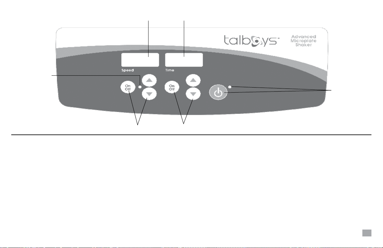
a. Plug the power cord into a properly ground outlet. The standby indicator light
will illuminate, verifying power to the unit.
b. Press the standby button to move the unit from standby mode. The standby
indicator light will turn off and the speed and time displays will illuminate,
displaying previously used settings.
2. Setting speed:
a. Press the up/down arrows below the speed display until you reach the desired
speed. When you release the button, the display will blink off and then on
indicating the new set speed has been accepted.
b. Press the on/off button to start the shaking function. The indicator light below
the speed display will illuminate to indicate the shaking function is in use and
remain lit until shaking has ceased. The microprocessor controlled ramping feature
slowly increases speed until the set-point is reached which helps to avoid
splashing, and provides excellent low end control.
c. Speed adjustments can be made without interrupting shaking by using the up/
down arrows below the speed display. After the change has been made and
you release the button, the display will blink off and then on indicating the new
set speed has been accepted.
d. To stop the shaking function, press the on/off button below the speed display.
The speed indicator light will turn off.
3. Setting time to zero (0:00) and continuous mode: Accumulated time.
a. Press and hold the on/off button below the time display. After three (3) seconds
the display will indicate the previous set time.
b. Simultaneously press both the up and down arrows, the display will indicate
zero (0:00). The unit time is now set to zero (0:00) minutes. Alternately, you can
use the up/down arrows to get to zero (0:00).
c. Press the on/off button below the time display. The display will indicate
accumulated time. The up/down arrows will become inactive. To stop timer,
press the on/off button again. IMPORTANT: This will NOT interrupt the shaking
function. Press the on/off button below the speed display to interrupt the
shaking function.
d. To reset, press and hold the on/off button below the time display. After three (3)
seconds the display will indicate the previous set time, which was zero (0:00).
4. Setting timed mode: Programmed time.
a. Press the up/down arrows below the time display until you reach the desired
time.
b. Start this function by pressing the on/off button below the time display. The unit
will run for the selected time, the up/down arrows will become inactive while the
timer is running. The unit will stop shaking when the time display reaches zero
(0:00). Four (4) audible beeps will indicate the count down function is complete.
The time display will default back to the set time. To repeat for the same time,
simply press the on/off button again.
c. To interrupt an automatic timing cycle before it is completed, press the on/off
button below the time display. The display will flash off and on to indicate the
time function is on “hold”. IMPORTANT: This will NOT interrupt the shaking
function. Press the on/off button below the speed display to interrupt the
shaking function. Restart the timer by pressing the on/off button below the
time display. Unit will continue counting down to zero (0:00). When the display
reaches zero (0:00), you will hear the four (4) audible beeps that indicate the
count down function is complete and shaking function will cease.
aDvanCeD orbital/MiCroPlate shaker oPerating instruCtions
9

5. Turning unit off:
a. To turn the unit off, press the standby button. The speed and time displays
will be blank, the standby indicator light will illuminate. The Orbital/Microplate
Shaker should be kept in standby mode when not in use. To completely cut off
power to the unit, disconnect the power cord from the unit or unplug from the
wall outlet.
OPERATING TIPS
As a safety feature, a built-in program will shut power off to the motor if the tray is
prevented from rotating, or the unit is overloaded beyond its recommended weight
capacity.
Built-in memory maintains the last used speed and time settings during a power
interruption.
During operation, any rattling or ticking sounds may indicate a loose screw on the tray,
a tray attachment or an accessory. All accessories should be sufficiently tightened in
place before starting the unit.
Error Code Software Test Cause
E04 unit overloaded maximum load exceeded
loose foot (suction cup)*
Press the standby button to clear this error. Be sure the load is within the maximum
load capacity before restarting the unit. If the E04 error persists, switch the unit off and
contact your Talboys representative for repairs.
Error Code Software Test Cause
E03 drive system failure ceased bearing
drive belt broken
mechanical obstruction
loose foot (suction cup)*
Press the standby button to clear this error and remove the mechanical obstruction.
If the E03 error persists the reason may be a ceased bearing or broken drive belt
and should NOT be addressed by the end user. Switch the unit off and contact your
Talboys representative for repairs.
*In the event a foot (suction cup) has come loose from the bench top, the unit will
register an errant E04 or E03 error message due to the instability of the unit. Press the
standby button to clear this error. Firmly press down on the four (4) corners of the unit,
creating a strong suction to the work surface (DO NOT place on bench mat). Press the
standby button to resume operation.
oPerating instruCtions Cont’Dtroubleshooting
10

1.
2.
3.
4.
5.
6.
7.
8. 10.
9.
aDvanCeD 1000-3 orbital shaker rePlaCeMent Parts
DesCriPtion Part nuMber
1. Front panel membrane switch 385703-00
2. Tray 580050-00
3. Display board 380780-00
4. Belt 580019-00
5. Motor 380712-00
6. Motor transition board 380415-00
7. Connection cable 380720-00
8. IEC power entry module 386122-00
9. Feet (suction cup) 545014-00
10. Detachable 92” (234cm) power cord: 120V 330100-00
Euro plug 330101-00
UK 330102-00
Swiss plug 330103-00
11

1. 2.
3.
4.
5.
6.
7. 8. 10.
9.
aDvanCeD 1000MP MiCroPlate shaker rePlaCeMent Parts
DesCriPtion Part nuMber
1. Front panel membrane switch 385702-00
2. Tray assembly 880761-00
3. Display board 380780-00
4. Belt 580019-00
5. Motor 380712-00
6. Motor transition board 380415-00
7. Connection cable 380720-00
8. IEC power entry module 386122-00
9. Feet (suction cup) 545014-00
10. Detachable 92” (234cm) power cord: 120V 330100-00
Euro plug 330101-00
UK 330102-00
Swiss plug 330103-00
12

FLASK CLAMPS
PlatforM Part
DesCriPtion Material CaPaCity nuMber
10mL Erlenmeyer Flask Clamp stainless steel 35 980078
25mL Erlenmeyer Flask Clamp stainless steel 20 980079
50mL Erlenmeyer Flask Clamp stainless steel 15 980080
125mL Erlenmeyer Flask Clamp stainless steel 12 980081
250mL Erlenmeyer Flask Clamp stainless steel 6 980082
500mL Erlenmeyer Flask Clamp stainless steel 4 980083
500mL Media Bottle Clamp stainless steel 3 980092
125mL Erlenmeyer Flask Clamp PVC 12 980428
250mL Erlenmeyer Flask Clamp PVC 6 980429
500mL Erlenmeyer Flask Clamp PVC 4 980430
aCCessories
TEST TUBE RACKS
tube PlatforM Part
DesCriPtion CaPaCity CaPaCity nuMber
10 to 13mm Test Tube Rack 63 2 980193
14 to 16mm Test Tube Rack 48 2 980194
18 to 20mm Test Tube Rack 35 2 980195
22 to 25mm Test Tube Rack 24 2 980196
15mL Centrifuge Tube Rack 42 2 980198
50mL Centrifuge Tube Rack 12 2 980199
1.5 to 2mL Micro-Tube Rack 70 2 980191
Installation of Flask Clamps - Orbital Shaker
1. Unit should be in standby mode.
2. Remove non-skid rubber mat.
3. Line up the hole(s) in the flask clamp to the hole(s)
in the tray. Using the screw(s) provided, hand
tighten into place using a flathead screwdriver.
DO NOT over tighten.
4. Insert flask/media bottle into clamp and wrap the
spring around the neck of the clamp to hold secure.
Not for use with the Microplate Shaker.
Installation of Test Tube Racks - Orbital Shaker
1. Unit should be in standby mode.
2. Remove non-skid rubber mat.
3. Align the clip on the rack to the right side of the tray.
4. Line up the holes in the test tube rack to the holes in the tray. Using the screws
provided, hand tighten into place using a flathead screwdriver. DO NOT over
tighten.
Installation of 1.5 to 2mL Micro-Tube Rack - Microplate Shaker
1. Unit should be in standby mode.
2. Align the Micro-Tube Rack side-to-side on the
tray.
3. Press the Micro-Tube Rack in place, you will
hear the Micro-Tube Rack clip into position. No
mounting screws are required.
13

aCCessories
Installation of Universal Harness - Orbital Shaker
1. Unit should be in standby mode.
2. Remove non-skid rubber mat.
3. Insert one band through the side of the “U” in the U-shaped cut-outs on the center
post. Pull band through to secure to the U-shaped cut-out. Repeat for the three
remaining bands.
4. After the bands are installed in the center post, line up the holes in center post with
the two holes in middle of the tray. Using the screws provoded, hand tighten into
place using a flathead screwdriver. DO NOT over tighten.
5. Place the sample(s) on tray.
6. Stretch the harness bands over the sample(s) and then under each of the bent-down
corners of the tray.
Not for use with the Microplate Shaker.
UNIVERSAL HARNESS
PlatforM Part
DesCriPtion MiCroPlate CaPaCity CaPaCity nuMber
Universal Harness 2 or 4 1 980192
Installation of 2-Bar Adjustable Platform - Orbital Shaker
1. Unit should be in standby mode.
2. Remove non-skid rubber mat.
3. Line up the holes in the 2-Bar Adjustable Platform to the holes in the tray.
Using the screws provided, hand tighten into place using a flathead screwdriver.
DO NOT over tighten.
4. Add glassware. Adjust rollers by loosening each of the thumbscrews. Slide the
padded rollers to the desired position and retighten the thumbscrews.
Not for use with the Microplate Shaker.
2-BAR ADJUSTABLE PLATFORM
The 2-Bar Adjustable Platform has a non-skid rubber surface with adjustable clamping
bars to accommodate various vessel types. Stainless steel construction.
PlatforM Part
DesCriPtion size (l xW) CaPaCity nuMber
2-Bar Adjustable Platform 11.7 x 8.7” (29.7 x 22.1cm) 1 980197
14

201 Wolf Drive • PO Box 87 • Thorofare, NJ 08086 • Phone: 1-888-TALBOYS • Fax: 856-686-1601
E-mail: [email protected] • www.troemner.com
715082-00 (REV 6 - 5/15)
Manufactured by:
This manual suits for next models
1
Table of contents
Popular Paint Sprayer manuals by other brands

Central Pneumatic
Central Pneumatic 90985 Assembly and operating instructions

Power Fist
Power Fist HVLP user manual

Firestone
Firestone W563581081 Technical Information Sheet

Titan
Titan ED655 operating manual

C.A. Technologies
C.A. Technologies Lynx 100H Product information

Makita
Makita BVF104 instruction manual

Graco
Graco Delta Spray 7031A Instructions-parts list

VEVOR
VEVOR 4X3X2.75 user manual

Chicago Electric
Chicago Electric CORDLESS SPRAY GUN 90880 Assembly and operating instructions

Graco
Graco 16N661 Operation - repair - parts

Villager
Villager VBS 16 Li ORIGINAL OWNER'S MANUAL

Graco
Graco 232411 Instructions-parts list